Cochlear implant electrode lead having a cross-section with variable height
US20110201997A1
2011-08-18
13/058,095
2009-07-08
✅ Patent granted
US 8,874,240 B2
2014-10-28
WO; PCT/AU2009/000879; 20090708
WO; WO2010/015017; 20100211
Nicholas Lucchesi | Melissa A Snyder
K&L Gates LLP
2030-10-02
Abstract:
An electrode lead for a cochlear implant, the electrode lead having a lateral side and a medial side supporting an electrode array, wherein a height of a cross section of the electrode lead is greater in the lateral side than a height of the cross section in the medial side.
Inventors:
- Fysh Dadd 57 🇦🇺 Lane Cove, Australia
- Peter Schuller 20 🇦🇺 Turramurra, Australia
- Claudiu Treaba 14 🇺🇸 Centennial, CO, United States
- Fysh Dadd 8 🇦🇺 New South Wales, Australia
- Peter Schuller 4 🇦🇺 New South Wales, Australia
Assignee:
- Cochlear Limited 174 🇦🇺 Lane Cove, Australia
- Cochlear Limited 486 🇦🇺 Macquarie University NSW, Australia
Applicant:
Interested in similar patents?
Get notified when new applications in this technology area are published.
Classification:
Y10T29/49172 » CPC further
Metal working; Method of mechanical manufacture; Electrical device making; Conductor or circuit manufacturing; Assembling electrical component directly to terminal or elongated conductor with encapsulating by molding of insulating material
A61F11/04 IPC
Methods or devices for treatment of the ears or hearing sense ; Non-electric hearing aids; Methods or devices for enabling ear patients to achieve auditory perception through physiological senses other than hearing sense; Protective devices for the ears, carried on the body or in the hand Methods or devices for enabling ear patients to achieve auditory perception through physiological senses other than hearing sense, e.g. through the touch sense
H01R43/24 IPC
Apparatus or processes specially adapted for manufacturing, assembling, maintaining, or repairing of line connectors or current collectors or for joining electric conductors for assembling or disassembling contact members with insulating base, case or sleeve Assembling by moulding on contact members
A61N1/0541 » CPC main
Electrotherapy; Circuits therefor; Details; Electrodes for implantation or insertion into the body, e.g. heart electrode; Head electrodes Cochlear electrodes
A61N1/05 IPC
Electrotherapy; Circuits therefor; Details; Electrodes for implantation or insertion into the body, e.g. heart electrode
A61N1/00 IPC
Electrotherapy; Circuits therefor
H04R25/00 IPC
Deaf-aid sets, i.e. electro-acoustic or electro-mechanical hearing aids; Electric tinnitus maskers providing an auditory perception
H04R25/606 » CPC further
Deaf-aid sets, i.e. electro-acoustic or electro-mechanical hearing aids; Electric tinnitus maskers providing an auditory perception; Mounting or interconnection of hearing aid parts, e.g. inside tips, housings or to ossicles of acoustic or vibrational transducers acting directly on the eardrum, the ossicles or the skull, e.g. mastoid, tooth, maxillary or mandibular bone, or mechanically stimulating the cochlea, e.g. at the oval window
Description
TECHNICAL FIELD
The present invention relates to cochlear implants and in particular, to the electrode of the implant.
INCORPORATION BY REFERENCE
The following documents are referred to in the following description:
- U.S. Pat. No. 6,421,569; and
- Australian Provisional Patent Application No. 2007906282 entitled “Electrode Array and Method”
The entire content of each of these applications is hereby incorporated by reference.
BACKGROUND
A cochlear implant allows for electrical stimulating signals to be applied directly to the auditory nerve fibres of a patient, allowing the brain to perceive a hearing sensation approximating the natural hearing sensation. These stimulating signals are applied by an array of electrodes implanted into the patient's cochlea.
The electrode array is connected to a stimulator unit which generates the electrical signals the delivery to the electrode array. The stimulator unit in turn is operationally connected to if signal processing unit which also contains a microphone for receiving audio signals from the environment, and for processing these signals to generate control signals for the stimulator.
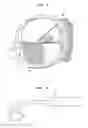
FIG. 1 shows a diagramatically-representative cross section of a cochlea. Shown there are three channels, known as the Scala Tympani, the Scala Media and the Scala Vestibuli. In use, an electrode lead containing the electrode array is inserted into the Scala Tympani and caused to make contact with the modiolar wall of the Scala Tympani, close to the ganglion cells within the modiolus.
It is desirable that electrode contacts of the electrode array are positioned as close to the ganglion cells as possible. The spiral ganglion cells lie in the bone or modiolus, adjacent to the inside wall of the scala tympani as shown in FIG. 1. Conventionally, after implantation, the electrode array consisting of electrode contacts should hug the modiolar wall or inside wall of the scala tympani). When the electrode array is positioned to the modiolar wall, the electrode contacts are on the medial side of the lead.
In order to facilitate close contact of the electrode contacts of the electrode array, the carrier material forming the electrode lead is moulded to assume a specific pre-curved shape having memory. Therefore the natural resting position of the lead has a curved distal lead tip. When the array tip is straightened (for example by stylet insertion tube), the tip stores elastic energy which exerts a force tending to restore the lead to its originally-moulded curved shape. When the lead is implanted the medial side of the lead hugs the modiolar wall and thus achieves a medial electrode array placement.
It is an object of the present invention to provide an alternative lead and method of improving the contact between electrode contact and the wall of the cochlea.
SUMMARY
According to one aspect of the present invention, there is provided an electrode lead for a cochlear implant, the lead having a lateral side and a medial side supporting an electrode array, wherein a height of a cross section of the electrode lead is greater in the lateral side than a height of the cross section in the medial side.
In one form, the medial side substantially conforms to the wail of the scala tympani of the cochlea.
In one form, the cross section of the electrode lead is substantially muffin-shaped.
In one form, the cross section of the electrode lead varies at least once along the electrode length of the lead so as to vary a curving force along the length of the electrode lead.
In one form, the electrode array is provided as an integral array assembly.
According to a second aspect of the present invention, there is provided a method of controlling a pressing force of an electrode lead, having a medial side supporting an electrode array and a lateral side, between one or more electrode contacts of the electrode array and a wall of a cochlea at a particular region, the method comprising controlling an amount of material in the electrode lead in the lateral side at the particular region so as to impart the required pressing force.
DRAWINGS
The various aspects of the present invention will now be described in detail with reference to the following figures in which;
FIG. 1—shows a cross section through a cochlea;
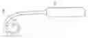
FIG. 2—shows a lead according to one aspect of the present invention;
FIG. 3—shows a cross section along the line A-A′ in FIG. 2;
FIG. 4—shows a cross section of the lead of FIGS. 2 and 3 overlaid over a cross section of a conventional electrode lead;
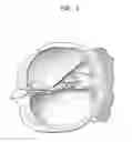
FIG. 5—shows a cross section of a cochlea with the lead of FIG. 2 inserted;
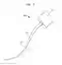
FIG. 6—shows an electrode lead in its carved state;
FIG. 7—shows a cross section for hail of a moulding die used in forming the electrode lead of FIG. 7;
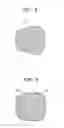
FIG. 8—shows a perspective view of an electrode lead according to one aspect of the present invention;
FIG. 9—shows a cross section of an electrode lead according to one aspect of the present invention including exemplary dimension; and
FIG. 10a-10e—show variations of possible cross sections of an electrode lead according to one aspect of the present invention.
FIG. 11—shows an electrode contact assembly that may be used with the present invention;
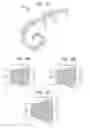
FIG. 12—shows an electrode lead according to one aspect of the invention with varying dimensions; and
FIGS. 13A to 13C—show cross sections at different points in FIG. 12.
DETAILED DESCRIPTION
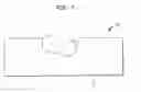
FIG. 2 shows an exemplary electrode lead 10 extending from a stimulator 20 of a cochlear implant system 100 which in use, is implanted into a user.
According to one aspect of the present invention, electrode lead 10 is shaped so as to have a cross section such that the height of the cross section is greater at the lateral side than at the medial side. FIG. 3 shows the cross section of the electrode lead 10 along the line A-A′ in FIG. 2. From the perspective of FIG. 2, the right hand side of the cross section is the lateral side, and the left hand side is the medial side. In one specific form of this, the electrode lead is substantially muffin-shaped, resembling a muffin on its side.
FIG. 4 shows the cross section of FIG. 3 superimposed over the cross section of a conventional electrode lead 10′ as described in U.S. Pat. No. 6,421,569 (previously incorporated by reference).
FIG. 5 shows a simplified cross section of the cochlea 50. In use, the electrode lead 10 will be positioned such that the medial side contacts the inner wall 53 of the Scala Tympani 51, close to the Spiral Ganglion.
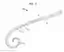
FIG. 6 shows electrode lead 10 in its natural state with bias into a curved state, with memory to resume that state after temporary straightening during insertion.
Below is a description of one method of forming an electrode lead embodying this aspect of the present invention.
Welding of Electrode Contacts (as known in the art, for example as described in U.S. Pat. No. 6,421,569)
-
- a) The contacts are formed by slicing 0.3 mm wide sections of Platinum Tube
- b) The contacts are placed in a Welding Jig and squashed to a U shape
- c) A bundle of 22 wires is placed in the Welding Jig.
- d) Each wire is connected to a contact (eg by welding). The strand travels from the contact proximally in bottom of all the proximal U-shaped contacts)
Formation of Welded Sub-assembly (as known in the art, for example as described in U.S. Pat. No. 6,421,569)
-
- a) A droplet of silicone is then placed in the trough of each electrode contact to secure the wires.
- b) The production stylet (PTFE coated wire) is pressed on top of the strands and silicone in the troughs of the electrode contacts (this stylet is removed later and forms the lumen).
- c) Each electrode trough is then partially filled with more silicone.
- d) The sub-assembly is then placed in an oven to cure the silicone.
- e) The assembly is then removed from the straight die
Moulding of electrode array (as known in the art, the example in U.S. Pat. No. 6,421,569)
-
- a) The sub-assembly is carefully curved to match the shape of a curved moulding the (described in more detail below with reference to FIG. 7) which will provide the cross section as described above. The assembly is then placed in the curved moulding die with the contacts being located closer to the medial side (inside of the curve).
- b) The space in the die is packed with silicone material.
- c) A matching die cover is placed over the assembly and pressed down.
- d) The die is then placed in an oven to cure the silicone.
- e) The die is then open to allow the resulting electrode area to be removed from the die.
FIG. 7 shows a cross section of one half 31 of a moulding die 30 suitable for use in the method described above. Shown there is the hall-die 31 having a cavity in which the sub-assembly and silicone are placed. As can be seen, the cavity provides a greater height for the electrode lead at one site 32 than at the other side 33. This will provide the molded electrode lead cross section as shown in FIG. 3.
FIG. 8 shows a perspective view of an electrode lead 10 manufactured by the method described above. It can be seen that the precurved electrode lead 10 has a lateral side 12 greater than a medial side 13. Electrode contacts 11 are shown disposed in the medial side 13.
FIG. 9 shows a cross section of the electrode lead 10, showing exemplary dimensions. In this example, the lateral side is about 0.8 mm and the medial side is about 0.6 mm. In some embodiments, these dimensions may range on the lateral side from about 0.5 mm to about 1.2 mm, and on the medial side from about 0.4 to about 0.8 mm.
It will also be understood that the “muffin-shape” is but one possible shape, and any other suitable shape may be used. FIGS. 10a to 10e show a non-exhaustive range of other possible shapes that may be used instead of the “muffin-shape” as described above, in which a height in the cross section of the lateral side is greater than a height in the cross section at the medial side. In some of these cases, it will be appreciated that the medial side may become the lateral side after about halfway across the cross section. Accordingly, the maximum height at the lateral side may occur anywhere between the halfway mark of the cross section, to the end of the cross section. The fourth possible cross section as shown in FIG. 10d shows the maximum height beginning at the halfway mark and remaining constant until the end of the lateral side. In other cross sections, the height of the cross section on the lateral side may reduce towards the end of the cross section in the lateral side after a maximum in the lateral side, such as in FIG. 10b and indeed, in the “muffin shaped” cross section described above. In other arrangements, as shown in FIG. 10a, the maximum height is at the very end of the cross section on the lateral side.
The present invention has particular advantage when used with an integrated electrode contact assembly, as described in Australian Provisional Patent Application No. 2007906282 (previously incorporated by reference).
In this arrangement, electrode contacts are punched out from a platinum strip into a comb 200 having a spine 210, as shown in FIG. 11, to provide efficiency and support in providing all 22 contacts for an automated welding operation. While it is possible to from a spine with multiple tapers, it is easier for manufacturing to have the forming of the spine with a constant taper (or no taper).
With a single taper the electrode array can not match the taper of the Scala Tympani as the Scala Tympani has a continuously varying taper as will be appreciated by the person skilled in the art.
The present invention allows for an electrode array where the carrier portion has a varying taper to align ideally, or at least more closely, with the Scala Tympani while allowing the electrode contacts to have a single taper. Note that this is the ideal situation as the basilar membrane is a very delicate structure but, is most impacted in modiolus hugging electrode by the lateral half of the electrode.
The electrode is formed in one example, is the following process steps (again, as described in Australian Provisional Patent Application No. 2007906282):
-
- 1. The finished Comb is placed into a welding jig ready for wires to be joined to the comb. The comb is secured by being held along the length of the Spine (a secure hold).
- 2. a wire is welded to the most proximal electrode contact
- 3. a droplet of silicone is placed in the trough of the electrode contact
- 4. a second wire is welded to the second roost proximal electrode contact
- 5. the wire from the second contact is bedded down into the silicone droplet in the trough of the first electrode
- 6. a droplet of silicone is placed in the trough of the second electrode contact
- 7. A thud and subsequent wires are welded in a similar manner
- 8. A production stylet (PTFE coated wire) is placed on top of the wires (this stylet is removed later and thrills the lumen).
- 9. Silicone is placed above each contact over the Production Stylet
- 10. The Silicone is cured in an oven
- 11. The sub-assembly is removed from the Welding Jig
- 12. The Spine is then Cut off the Comb
Moulding of electrode array (as known in the art, e.g. U.S. Pat. No. 6,421,569), with new moulding die (for example as shown in FIG. 7).
-
- a) The sub-assembly is carefully curved to match the shape of a new curved moulding die. The assembly is then placed in the curved moulding die with the contacts being located closer to the medial side (inside of the curve).
- b) The space in the die is packed with silicone material.
- c) A matching die cover is placed over the assembly and pressed down.
- d) The die is then placed in an oven to cure the silicone.
- e) The is then opened to allow the resulting electrode array to be removed from the die.
The carrier which forms the body of the lead can be made from any suitable material including silicone, polyurethanes or other body compatible polymeric insulating, materials. The type and hardness of the insulating carrier can be selected to provide a specific, desired compliance to the lead body in combination with the compliance of the conductor wires and choice of structures incorporated into the lead.
As described above, while the example given refers to electrode contacts with a single taper (or no taper at all), there could also be provided multi-tapering electrode contacts. These could be any number of tapers. Current, prior art designs, have typically 3 separate tapers, for example near the proximal end there is no taper but constant width, then it taper, then distally a shallower taper.
It is also possible to have the “muffin” formed with any number of tapers from the intra-cochlea proximal region to the distal region. In one form, any tapers are transitioned smoothly so as the electrode array is presented as a smooth object into the cochlea.
Any combination of these features is also possible.
The present invention also allows for control of the amount of “pressing force” imparted on the electrode contacts against the wall of the cochlea by controlling the amount of material in the carrier at the lateral side. The more material provided in this region, the greater the curving force provided at that region. This greater curving force provides a greater pressing force to the electrode contacts against the wall of the cochlea. This is particularly useful as any inserted elements such as electrode wires, electrode contacts or support structures will have a natural resistance to curving, and wild counteract the curving force provided by the carrier material. In this way, the curving force may be tailored to the particular electrode lead design and may provide different localised curving forces to counter resistance from inserted elements as well as to control the pressing three at discrete regions along, the electrode lead to ensure that the electrode contacts are in contact with the wall of the cochlea regardless of changes or variations in the taper or shape of the scala tympani.
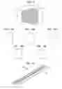
In one example, an electrode lead is designed to have a variety of different curving threes at different regions along the lead, by varying the amount of material at those regions. As shown in FIG. 12, the electrode lead has a first region A having a cross section in the earlier material as shown in FIG. 13A, a second region B having a cross section in the carrier material as shown in FIG. 13B and at third section C having a cross section in the carrier material as shown in FIG. 13C. The regions between these regions may be shaped so as to provide a smooth transition therebetween.
Example dimensions for these figures are shown in Table 1 below. Note that the “slices” are at different intra-cochlear depths, with FIG. 13A being most distal.
| TABLE 1 | ||||
| Dimension | FIG. 13A | 13B | 13C | |
| Pad height | 0.6 | 0.6 | 0.6 | |
| Muffin vertical | 0.65 | 0.7 | 0.8 | |
| Muffin horizontal | 0.6 | 0.75 | 0.8 | |
In the above examples, it will be noted that the ratio of the vertical and the horizontal height changes depending on the ultra-cochlea depth.
The various aspects of the present invention provide many advantages.
-
- Creates a safer electrode. A cross sectional shape that doesn't fit results in fewer pressure points (both during & after insertion), which can lead to localised or spread damage, particularly in the modiolus and the surrounding hard structures. The new design spreads any pressure into a larger area and is thus safer.
- None of the existing perimodiolar designs match the 3D curved surface of the modiolus. While their inner line is designed to fit that of a mean cochlear model, the electrode cross-section was not matched to the curve of the Scala Tympani cross-section.
The electrode lead described above forms the distal end of a lead/array assembly that is adapted to be connected to an implantable cochlear stimulator (ICS) (not shown). The lead/array assembly includes the electrode array, a helix section and a lead end to be connected to the ICS. The ICS is typically housed within a metallic case. The ease has an array of feed through terminals corresponding to its multiple channels.
Throughout the specification and the claims that follow, unless the context requires otherwise, the words “comprise” and “include” and variations such as “comprising” and “including” will be understood to imply the inclusion of a stated integer or group of integers, but not the exclusion of any other integer or group of integers.
The reference to any prior art in this specification is not, and should not be taken as, an acknowledgement of any form of suggestion that such prior art forms part of the common general knowledge.
Claims
1. An electrode lead for a cochlear implant, the electrode lead having a lateral side and a medial side supporting an electrode array, wherein a height of a cross section of the electrode lead is greater in the lateral side than a height of the cross section in the medial side.
2. An electrode lead as claimed in claim 1 wherein the medial side substantially conforms to the wall of the scala tympani of the cochlea.
3. An electrode lead as claimed in any one of claims 1 or 2 wherein the cross section of the electrode lead is substantially muffin-shaped.
4. An electrode lead as claimed in any one of claims 1 to 3 wherein the cross section of the electrode lead varies at least once along the electrode length of the lead so as to vary a curving force along the length of the electrode lead.
5. An electrode lead as clamed in any one of claims 1 to 4 wherein the electrode array is provided as an integral array assembly.
6. A method of controlling a pressing force of an electrode lead, having a medial side supporting an electrode array and a lateral side, between one or more electrode contacts of the electrode array and a wall of a cochlea at a particular region, the method comprising controlling an amount of material in the electrode lead in the lateral side at the particular region so as to impart the required pressing force.
Images & Drawings included:
Sources:
- United States Patent and Trademark Office - verify current appl. status at the USPTO↗
Recent applications in this class:
- » 20250288796 2025-09-18
HEARING PERCEPT PARAMETER ADJUSTMENT STRATEGY FOR A HEARING PROSTHESIS - » 20250269171 2025-08-28
IMPLANTABLE COCHLEAR SYSTEM WITH INTEGRATED COMPONENTS AND LEAD CHARACTERIZATION - » 20250235693 2025-07-24
MODULAR IMPLANT POSITION MANIPULATOR SYSTEM - » 20250229082 2025-07-17
CONTROLLED POSITION ELECTRODE ARRAY - » 20250222251 2025-07-10
IMPLANTABLE STIMULATION ARRANGEMENT STRUCTURES - » 20250195880 2025-06-19
IMPLANTABLE STIMULATING ASSEMBLY WITH MUSCLE - » 20250177734 2025-06-05
SYSTEM AND METHOD FOR DETERMINING A POSE OF A COCHLEAR IMPLANT - » 20250177733 2025-06-05
INSTRUMENTED COCHLEAR IMPLANT - » 20250128057 2025-04-24
ASSEMBLIES, ELECTRODE LEADS, AND METHODS FOR STEERING AN ELECTRODE LEAD DURING INSERTION INTO A COCHLEA - » 20250082926 2025-03-13
IMPLANTABLE STIMULATING ASSEMBLY
Recent applications for this Assignee:
- » 20210051426 2021-02-18
Systems for accommodating separation of body parts in auditory prostheses - » 20210007662 2021-01-14
Clinical fitting assistance using software analysis of stimuli - » 20200330776 2020-10-22
Shielding device for signal transmission coil - » 20200222661 2020-07-16
Cochlear implant electrode assembly insertion tool - » 20200162827 2020-05-21
Low-power active bone conduction devices - » 20200147399 2020-05-14
Feedthrough arrangement for medical device - » 20200112802 2020-04-09
Systems and method for adjusting auditory prostheses settings - » 20200045483 2020-02-06
Bone conduction devices utilizing multiple actuators - » 20190074585 2019-03-07
Implantable medical device with multi-band loop antenna - » 20190060649 2019-02-28
Noise reduction for implantable hearing prostheses