Plate Position Display Vibration Machine
US20110227752A1
2011-09-22
12/726,745
2010-03-18
Abstract:
The Plate Position Display Vibration Machine is a Whole Body Vibration Machine which represents visually the oscillating plate position as a ratio of the actual position.
Interested in similar patents?
Get notified when new applications in this technology area are published.
Classification:
A61H23/02 » CPC further
Percussion or vibration massage, e.g. using supersonic vibration; Suction-vibration massage; Massage with moving diaphragms with electric or magnetic drive
A61H2201/5043 » CPC further
Characteristics of apparatus not provided for in the preceding codes; Control means thereof; Interfaces to the user Displays
G09F9/33 » CPC main
Indicating arrangements for variable information in which the information is built-up on a support by selection or combination of individual elements in which the desired character or characters are formed by combining individual elements being semiconductor devices, e.g. diodes
Description
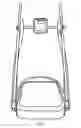
A Whole Body Vibration Machine consists of a vibrating base, with handle supports, which ressembles a treadmill, but not as large. Vibration Machines are now widely available for sale. An example of a Vibration Machine is in FIG. 1.
One type of machine is the Oscillating (side-alternating or pivotal) machine. The plate on an Oscillating machine “see-saws” from side to side as shown in FIG. 2. Each side goes up and down. How far up and down the plate moves at the outer edge is the amplitude (usually about 10 mm). The amplitude is shown by the arrows in FIG. 2.
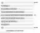
The purpose of this invention is to invent a vibration machine that shows the position of the plate edge visually, for example by a moving straight line simulating the platform (as in FIG. 3) or a moving linear set of LEDs (FIG. 4). The plate position, whether at the extreme top or bottom on each side or points in between, is shown visually. Since the actual plate position may be too fast to show, the display will be a ratio of the actual position.
DRAWINGS
FIG. 1 shows a Vibration Machine
FIG. 2 shows an oscillating plate
FIG. 3 shows a plate simulation at several positions
FIG. 4 shows a moving set of LEDs simulating the plate left edge position
Claims
1. We claim a Vibration Machine with visual display of the oscillating plate position, as shown and described.
Images & Drawings included:


Sources:
- United States Patent and Trademark Office - verify current appl. status at the USPTO↗
Recent applications in this class:
- » 20250174160 2025-05-29
DISPLAY PANEL ADAPTED TO SPHERICAL DISPLAY DEVICE AND CONFIGURATION METHOD THEREOF - » 20250054421 2025-02-13
TRANSPARENT DISPLAY DEVICE - » 20240274042 2024-08-15
DISPLAY DEVICE, DECORATIVE SHEET, AND METHOD FOR PRODUCING DISPLAY DEVICE - » 20240233584 2024-07-11
SIGNBOARD ASSEMBLY AND FULLY TRANSPARENT SOLAR LED LUMINOUS SIGNBOARD - » 20240177634 2024-05-30
Display backplane and preparation method therefor, and display apparatus - » 20240161662 2024-05-16
On-air status indicator - » 20240161661 2024-05-16
Portable food concession trailer - » 20240135841 2024-04-25
Signboard assembly and fully transparent solar LED luminous signboard - » 20240127721 2024-04-18
System for dry execution of finishing material - » 20240119871 2024-04-11
Video-Audio Output Module And Video-Audio Presentation Apparatus