Method for mapping a physical downlink control format indicator channel to physical resources
US20110228729A1
2011-09-22
12/673,452
2008-10-22
✅ Patent granted
US 8,102,755 B2
2012-01-24
WO; PCT/CN2008/072789; 20081022
WO; WO2009/059517; 20090514
Seema S Rao | Khoa Huynh
2029-04-22
Abstract:
A method for mapping a physical downlink control format indicator channel to physical resources includes the steps that 16 modulated data y(0), y(1), . . . , y(15) of a downlink control signaling indicator channel in an LTE system are divided into 4 groups in order and mapped by groups, which allows the downlink control format indicator channel to be mapped exactly to the continuous 4 resource elements recombined by resources which are divided among all system physical resources except the pilots according to such continuous 4 resource elements. By defining group mapping rules, this method can offer the maximum gain of frequency selectivity.
Inventors:
- Shuqiang Xia 220 🇨🇳 Shenzhen, China
- Bo Dai 513 🇨🇳 Shenzhen, China
- Guanghui Yu 139 🇨🇳 Shenzhen, China
- Zhisong Zuo 62 🇨🇳 Shenzhen, China
Assignee:
- ZTE Corporation 3,493 🇨🇳 Shenzhen, China
- ZTE CORPORATION 1,440 🇨🇳 Shenzhen, Guangdong, China
Interested in similar patents?
Get notified when new applications in this technology area are published.
Classification:
H04L5/0073 » CPC main
Arrangements affording multiple use of the transmission path; Arrangements for allocating sub-channels of the transmission path; Allocation criteria Allocation arrangements that take into account other cell interferences
H04L5/0053 » CPC further
Arrangements affording multiple use of the transmission path; Arrangements for allocating sub-channels of the transmission path Allocation of signaling, i.e. of overhead other than pilot signals
H04L5/0007 » CPC further
Arrangements affording multiple use of the transmission path; Arrangements for dividing the transmission path; Two-dimensional division; Time-frequency the frequencies being orthogonal, e.g. OFDM(A), DMT
H04W72/04 IPC
Local resource management, e.g. wireless traffic scheduling or selection or allocation of wireless resources Wireless resource allocation
H04J11/00 IPC
Orthogonal multiplex systems, e.g. using WALSH codes
Description
TECHNICAL FIELD
The present invention relates to the field of broadband wireless communication systems, especially to a method for mapping a physical downlink control format indicator channel to physical resources in a 3GPP Long Term Evolution (shortened as LTE) system.
BACKGROUND
In an LTE system, since resources exist in two dimensions, i.e. time and frequency. Accordingly, the allocation of the resources and their representation method become quite complicated, especially when a bandwidth is relatively wide, consideration must be given to such requirements as not only the flexibility of the resources allocation but also the size of the related bandwidth, etc.
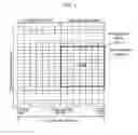
FIG. 1 is a schematic illustration of a resource block and a resource element in a 3GPP LTE (with 5M-bandwidth) system. It is specified in the LTE system that the length of a sub-frame in time is 1 ms, and one sub-frame is comprised of two equal time slots (Time Slot 1 and Time Slot 2), the length of time of each time slot is 0.5 ms. One resource element contains one Orthogonal Frequency Division Multiplexing (shortened as OFDM) symbol, and one subcarrier in each OFDM symbol belongs to the resource element. While the usual method of resource representation is defining a basic Resource Block (shortened as RB), and then carrying out the resources allocation in the unit of RB.
In the LTE system, a downlink mainly includes multiple downlink channels such as a Physical Control Format Indicator Channel (shortened as PCFICH), etc. A representation method for mapping a physical downlink control format indicator channel to physical resources is given in a current draft standard, which is specifically described as below:
mapping y(0), . . . y(3) to the resource elements in which a resource element group k locates, and k=k0;
mapping y(4), . . . y(7) to the resource elements in which a resource element group k locates, and k=k0+└NDLRB/4┘;
mapping y(8), . . . y(11) to the resource elements in which a resource element group k locates, and k=k0+└2NDLRB/4┘;
mapping y(12), . . . y(15) to the resource elements in which a resource element group k locates, and k=k0+└3NDLRB/4┘;
wherein, k0=NcellIDmod(NDLRB/2, and it is necessary to carry out a modulus of NDLRBNRBsc on k;
wherein, y(0), . . . , y(15) stand for the data in the physical downlink control format indicator channel after code modulation, and the NDLRB stands for the quantity of resource blocks in the system bandwidth, and the NcellID is the proprietary ID (identity) of each cell.
Taking the 3GPP LTE (with 5M-bandwidth) system for example, as shown in FIG. 1, a 5M-bandwidth downlink in the LTE contains a total of 512 subcarriers, the 300 of which in the middle are usable subcarriers; each resource block contains continuous 12 subcarriers, therefore the 5M bandwidth contains a total of 25 resource blocks.
One resource block contains 4 pilot elements, and except the pilots, every four remaining resources elements are combined into a resource element group, so there are a total of 50 resource element groups.
The physical downlink control format indicator channel is mapped to the first OFDM symbol in a sub-frame.
Assuming that the ID of the target cell is 13 and that the initial position of the pilot on the first antenna port is the third subcarrier, then:
according to the existing technologies, and k0=NcellIDmod(NDLRB/2); when the NDLRB is an odd number, the k0 would be a decimal number, which does not offer any practical physical meaning; and
moreover, even if k0=NcellIDmod(└NDLRB/2┘) or k0=NcellIDmod(┌NDLRB/2┐), there is still a problem that the performance is not optimal.
y(0), . . . y(15) in the physical downlink control format indicator channel are mapped to the following physical resources by dividing 4 continuous subcarriers in order except the pilots into one group:
wherein, y(0), . . . , y(15) stand for the data in the physical downlink control format indicator channel after code modulation; the NDLRB stands for the quantity of the resource blocks in the system bandwidth; and the NcellID is the proprietary ID of each cell.
k0=NcellIDmod(NDLRB/2)=13mod(└25/2┘)=1, and it is necessary to carry out a modulus of NDLRB×NRBsc=25×12=300 on k;
y(0), . . . y(3) are mapped to the resource elements in which a resource element group k locates, and k=k0=1;
y(4), . . . y(7) are mapped to the resource elements in which the resource element group k locates, and k=k0+└NDLRB/4┘=1└25/4┘=7;
y(8), . . . y(11) are mapped to the resource elements in which the resource element group k locates, and k=k0+└2×NDLRB/4┘=1+└2×NDLRB/4┘=13; and
y(12), . . . y(15) are mapped to the resource elements in which the resource element group k locates, and k=k0+└3×NDLRB/4 ┘=1+└3×25/4┘=19.
FIG. 2 is a schematic illustration of mapping a physical downlink control format indicator channel in a 3GPP LTE (with 5M-bandwidth) system according to relevant technologies. As shown in FIG. 2, the code-modulated data y(0), . . . , y(15) in the downlink control format indicator channel are mapped to the resource elements numbered 6, 7, 9, 10 and 42, 43, 45, 46 as well as 78, 79, 81, 82 and 114, 115, 117, 118.
It can be seen in FIG. 2 that the range of physical elements which are mapped to a physical downlink control format indicator channel by the existing solution is only half of the bandwidth, without obtaining a maximum gain of frequency selectivity.
In the LTE system, the resources in the physical downlink control format indicator channel are allocated based on 4 continuous subcarriers as a group, while in the system bandwidth and except the pilots, the resources are divided into groups of 4 continuous subcarriers (the pilots are skipped over if they are encountered), so the total number of the groups is 2NDLRB (because one RB contains 12 carriers, while one RB also contains 4 subcarriers used for dual-antenna pilots). And there are 16 modulated data in the physical downlink control format indicator channel which need to be mapped onto 4 groups (each group has 4 subcarriers). If mapping should be carried out according to the formula in the above mentioned draft standard, then the data in the physical downlink control format indicator channel would be distributed unevenly over the entire system bandwidth, and thereby that is unable to obtain the maximum gain of frequency diversity.
SUMMARY
The present invention aims to solve the problem of uneven distribution of PCFICH data over the entire system bandwidth caused by the mapping methods in relevant technologies through providing a method for mapping a physical downlink control format indicator channel to physical resources.
The present invention provides a method for mapping a physical downlink control format indicator channel to physical resources, comprising: mapping data y(0), . . . y(15) in a physical downlink control format indicator channel to physical resources according to the following method by combining 4 continuous subcarriers in order except the pilots into a group: y(0), . . . y(3) are mapped to the resource elements in which a resource element group k1=k0 locates; y(4), . . . y(7) are mapped to the resource elements in which a resource element group k2=k0+└NDLRB/2┘ locates; y(8), . . . y(11) are mapped to the resource elements in which a resource element group k3=k0+└2NDLRB/2┘=k0+└NDLRB locates; y(12), . . . y(15) are mapped to the resource elements in which a resource element group k4=k0+└3NDLRB/2┘ locates; wherein: k0=NcellIDmod(└NDLRB/2┘ ), and the NDLRB stands for the quantity of resource blocks in the system bandwidth, and the NcellID is the proprietary ID of each cell.
The present invention also provides a method for mapping a physical downlink control format indicator channel to physical resources, comprising: mapping data y(0), . . . y(15) in a physical downlink control format indicator channel to physical resources according to the following method by combining 4 continuous subcarriers in order except the pilots into a group: mapping y(0), . . . y(3) to the resource elements in which a resource element group k1=k0mod(2×NDLRB) locates; y(4), . . . y(7) are mapped onto the resource elements in which a resource element group k2=(k0+└NDLRB/2┘)mod(2×NDLRB) locates; mapping y(8), . . . y(11) to the resource elements in which a resource element group k3=(k0+└NDLRB┘)mod(2×NDLRB) locates; mapping y(12), . . . y(15) to the resource elements in which a resource element group k4=(k0+└3NDLRB/2┘)mod(2×NDLRB)locates; wherein: k0=NcellIDmod(X*NDLRB), and the NDLRB stands for the quantity of resource blocks in the system bandwidth, and the NcellID is the proprietary ID of each cell, and the X is a positive integer.
Furthermore, when the X is 1, k0=NcellIDmod(NDLRB). At this time, mapping data y(0), . . . y(15) in a physical downlink control format indicator channel to physical resources according to the following method by combining 4 continuous subcarriers in order except the pilots into a group: y(0), . . . y(3) may be mapped to the resource elements in which a resource element group k1=k0mod(2×NDLRB) locates; y(4), . . . y(7) may be mapped to the resource elements in which a resource element group k2=(k0+└NDLRB/2┘)mod(2×NDLRB) locates; y(8), . . . y(11) may be mapped to the resource elements in which a resource element group k3=(k0+└NDLRB)mod(2×NDLRB) locates; and y(12), . . . y(15) may be mapped to the resource elements in which a resource element group k4=(k0+└3NDLRB/2┘)mod(2×NDLRB) locates.
Furthermore, when the X is 2, k0=NcellIDmod(2×NDLRB). At this time, mapping data y(0), . . . y(15) in a physical downlink control format indicator channel to physical resources according to the following method by combining 4 continuous subcarriers in order except the pilots into a group: y(0), . . . y(3) may be mapped to the resource elements in which a resource element group k1=k0mod(2×NDLRB) locates; y(4), . . . y(7) may be mapped to the resource elements in which a resource element group k2=(k0+└NDLRB/2┘)mod(2×NDLRB) locates; y(8), . . . y(11) may be mapped to the resource elements in which a resource element group k3=(k0+└NDLRB┘)mod(2×NDLRB) locates; and y(12), . . . y(15) may be mapped to the resource elements in which a resource element group k4=(k0+└3NDLRB/2┘)mod(2×NDLRB) locates.
Furthermore, when the X is 2, k0=NcellIDmod(2×NDLRB); at this time, mapping data y(0), . . . y(15) in a physical downlink control format indicator channel to physical resources according to the following method by combining 4 continuous subcarriers in order except the pilots into a group: y(0), . . . y(3) may be mapped to the resource elements in which a resource element group k1=NcellIDmod(2×NDLRB) locates; y(4), . . . y(7) may be mapped to the resource elements in which a resource element group k2=(NcellID+└NDLRB/2┘)mod(2×NDLRB) locates; y(8), . . . y(11) may be mapped to the resource elements in which a resource element group k3=(NcellID+└NDLRB┘)mod(2×NDLRB) locates; and y(12), . . . y(15) may be mapped to the resource elements in which a resource element group k4=(NcellID+└3NDLRB/2┘)mod(2×NDLRB) locates.
The present invention can offer the maximum gain of frequency diversity by defining group mapping rules to achieve even distribution of the data in a physical downlink control format indicator channel over the entire system bandwidth.
BRIEF DESCRIPTION OF THE DRAWINGS
The drawings described here are used to provide further understanding of the present invention and constitute a part of the present invention, and the illustrative embodiments for the present invention and their explanations are used to interpret the present invention and do not constitute any improper restriction on the present invention. Among the drawings:
FIG. 1 is a schematic illustration of a resource block and a resource element in a 3GPP LTE (with 5M-bandwidth) system based on relevant technologies;
FIG. 2 is a schematic illustration of mapping a physical downlink control format indicator channel in a 3GPP LTE (with 5M-bandwidth) system based on relevant technologies;
FIG. 3 is a schematic illustration of mapping a physical downlink control format indicator channel in a 3GPP LTE (with 5M-bandwidth) system corresponding to Method (1) based on the embodiments of the present invention; and
FIG. 4 is a schematic illustration of mapping a physical downlink control format indicator channel in a 3GPP LTE (with 5M-bandwidth) system corresponding to Method (2), Method (3) and Method (4) based on the embodiments of the present invention.
DETAILED DESCRIPTION
The exemplary embodiments of the present invention are described below based on the drawings attached; it should be understood that the exemplary embodiments described here are only used to describe and explain the present invention rather than limit the present invention.
Functional Overview
The main idea of the present invention is that: the 16 modulated data y(0), y(1), . . . , y(15) in a downlink control signaling indicator channel in the LTE system are divided into 4 groups in sequential order and mapped by groups, which allows the downlink control format indicator channel to be mapped exactly to continuous 4 resource elements recombined by resource element groups which are divided among all system physical resources except the pilots according to such continuous 4 resource elements in order to offer the maximum gain of frequency selectivity.
The present invention provides a method for mapping a physical downlink control format indicator channel to physical resources, comprising: mapping the data y(0), . . . y(15) in a downlink control format indicator channel to physical resources according to the following method by combining 4 continuous subcarriers in order except the pilots into a group:
Method (1) Mapping the data y(0), . . . y(15) in a physical downlink control format indicator channel to physical resources according to the following method by combining 4 continuous subcarriers in order except the pilots into a group:
y(0), . . . y(3) are mapped to the resource elements in which a resource element group k1=k0 locates;
y(4), . . . y(7) are mapped to the resource elements in which a resource element group k2=k0+└NDLRB/2┘ locates;
y(8), . . . y(11) are mapped to the resource elements in which a resource element group k3=k0+└2NDLRB/2┘ locates;
y(12), . . . y(15) are mapped to the resource elements in which a resource element group k4=k0+└3NDLRB/2┘ locates; and
wherein, k0=NcellIDmod(└NDLRB/2┘), and the NDLRB stands for the quantity of resource blocks in the system bandwidth, and the NcellID is the proprietary ID of each cell.
As shown in FIG. 3, after the above mentioned mapping processing, the code-modulated data y(0), . . . , y(15) in a physical downlink control format indicator channel are mapped to the resource elements numbered 6, 7, 9, 10 and 78, 79, 81, 82 as well as 156, 157, 159, 160 and 228, 229, 231, 232. The initial position of the physical resources in the physical downlink control format indicator channel lies at the first quarter position of the available bandwidth.
Method (2)
Mapping the data y(0), . . . y(15) in a physical downlink control format indicator channel to physical resources according to the following method by combining 4 continuous subcarriers in order except the pilots into a group:
y(0), . . . y(3) are mapped to the resource elements in which a resource element group k1=k0mod(2×NDLRB) locates;
y(4), . . . y(7) are mapped to the resource elements in which a resource element group k2=(k0+└NDLRB/2┘)mod(2×NDLRB) locates;
y(8), . . . y(11) are mapped to the resource elements in which a resource element group k3=(k0+└NDLRB┘)mod(2×NDLRB) locates;
y(12), . . . y(15) are mapped to the resource elements in which a resource element group k4=(k0+└3NDLRB/2┘)mod(2×NDLRB) locates; and
wherein, k0=NcellIDmod(NDLRB), the NDLRB stands for the quantity of resource blocks in the system bandwidth, and NcellID is the proprietary ID of each cell.
As shown in FIG. 4, after the above mentioned mapping processing, the code-modulated data y(0), . . . , y(15) in a physical downlink control format indicator channel are mapped to the resource elements numbered 78, 79, 81, 82 and 150, 151, 153, 154 as well as 228, 229, 231, 232 and 0, 1, 3, 4. The initial position of the physical resources in the physical downlink control format indicator channel lies at the first one-half position of the available bandwidth.
Method (3)
Mapping the data y(0), . . . y(15) in a physical downlink control format indicator channel to physical resources according to the following method by combining 4 continuous subcarriers in order except the pilots into a group:
y(0), . . . y(3) are mapped to the resource elements in which a resource element group k1=k0mod(2×NDLRB) locates;
y(4), . . . y(7) are mapped to the resource elements in which a resource element group k2=(k0+└NDLRB/2┘)mod(2×NDLRB) locates;
y(8), . . . y(11) are mapped to the resource elements in which a resource element group k3=(k0+└NDLRB┘)mod(2×NDLRB) locates;
y(12), . . . y(15) are mapped to the resource elements in which a resource element group k4=(k0+└3NDLRB/2┘)mod(2×NDLRB) locates; and
wherein, k0NcellIDmod(2×NDLRB) and the NDLRB stands for the quantity of resource blocks in the system bandwidth, and the NcellID is the proprietary ID of each cell.
As shown in FIG. 4, after the above mentioned mapping processing, the code-modulated data y(0), . . . , y(15) in a physical downlink control format indicator channel are mapped to the resource elements numbered 78, 79, 81, 82 and 150, 151, 153, 154 as well as 228, 229, 231, 232 and 0, 1, 3, 4. The initial position of the physical resources in the physical downlink control format indicator channel may lie at any position of the available bandwidth.
Method (4)
Mapping data y(0), . . . y(15) in a physical downlink control format indicator channel to physical resources according to the following method by combining 4 continuous subcarriers in order except the pilots into a group:
y(0), . . . y(3) are mapped to the resource elements in which a resource element group k1=NcellIDmod(2×NDLRB) locates;
y(4), . . . y(7) are mapped to the resource elements in which a resource element group k2 =(NcellID+└NDLRB/2┘)mod(2×NDLRB) locates;
y(8), . . . y(11) are mapped to the resource elements in which a resource element group k3=(NcellID+└NDLRB┘)mod(2×NDLRB)locates;
y(12), . . . y(15) are mapped to the resource elements in which a resource element group k4=(NcellID+└3NDLRB/2┘)mod(2×NDLRB) locates; and
wherein, the NDLRB stands for the quantity of resource blocks in the system bandwidth, and the NcellID is the proprietary ID of each cell.
As shown in FIG. 4, after the above mentioned mapping processing, the code-modulated data y(0), . . . , y(15) in a physical downlink control format indicator channel are mapped to the resource elements numbered 78, 79, 81, 82 and 150, 151, 153, 154 as well as 228, 229, 231, 232 and 0, 1, 3, 4. The initial position of the physical resources in the physical downlink control format indicator channel may lie at any position of the available bandwidth.
For above mentioned Method (3) and Method (4), the initial position of the physical resources in the physical downlink control format indicator channel may lie at any position of the available bandwidth. More initial positions mean that there are more mapping patterns of the physical downlink control format indicator channel. The more patterns there are, the better randomization degree of mutual interferences among the physical downlink control format indicator channels in neighboring cells will be obtained. For Method (3) and Method (4), only the forms of expression are different, but their mapping positions are the same.
The present invention can offer the maximum gain of frequency domain selectivity by defining group mapping rules to achieve even distribution of data in a physical downlink control format indicator channel over the entire system bandwidth; moreover, no error would arise even when the quantity of available resource blocks is an odd number.
Obviously, those skilled in the art should understand that the individual modules or individual steps in the present invention as mentioned above can be realized by using a general-purpose computing device, that they can be either integrated in a single computing device or distributed over a network comprised of multiple computing devices and that, optionally, they can be realized by using program codes executable by such a computing device so that they can be stored inside a storage device and executed by a computing device, or they can be individually made into individual integrated circuit modules, or they can be realized by making the multiple modules or steps in them into individual integrated circuit modules. In this way, the present invention is not restricted to any specific combination of hardware and software.
The above mentioned are the exemplary embodiments of the present invention only and are in no way intended to limit the present invention. For those skilled in the art, various modifications and changes may be made to the present invention. Any modification, equivalent substitute and improvement within the spirit of the present invention are deemed to be included within the scope of protection of the present invention.
Claims
1. A method for mapping a physical downlink control format indicator channel to physical resources, comprising:
mapping data y(0), . . . y(15) in a physical downlink control format indicator channel to physical resources according to the following method by combining 4 continuous subcarriers in order except the pilots into a group:
mapping y(0), . . . y(3) to the resource elements in which a resource element group k1=K0 locates;
mapping y(4), . . . y(7) to the resource elements in which a resource element group k2=k0+└NDLRB/2┘ locates;
mapping y(8), . . . y(11) to the resource elements in which a resource element group k3=k0+└2NDLRB/2┘=k0+└NDLRB┘ locates;
mapping y(12), . . . y(15) to the resource elements in which a resource element group k4=k0+└3NDLRB/2┘ locates; and
wherein, k0NcellIDmod(└NDLRB/2┘), and the NDLRB standing for the quantity of resource blocks in the system bandwidth, and the NcellID being the proprietary ID of each cell.
2. A method for mapping a physical downlink control format indicator channel to physical resources, comprising:
mapping data y(0), . . . y(15) in a physical downlink control format indicator channel to physical resources according to the following method by combining 4 continuous subcarriers in order except the pilots into a group:
mapping y(0), . . . y(3) to the resource elements in which a resource element group k1=k0mod(2×NDLRB) locates;
mapping y(4), . . . y(7) to the resource elements in which a resource element group k2=(k0+└NDLRB/2┘)mod(2×NDLRB) locates;
mapping y(8), . . . y(11) to the resource elements in which a resource element group k3=(k0+└NDLRB┘)mod(2×NDLRB) locates;
mapping y(12), . . . y(15) to the resource elements in which a resource element group k4=(k0+└3NDLRB/2┘)mod(2×NDLRB) locates; and
wherein, k0=NcellIDmod(X*NDLRB), and the NDLRB standing for the quantity of resource blocks in the system bandwidth, and the NcellID being the proprietary ID of each cell, and the X being a positive integer.
3. The method according to claim 2, wherein: when the X is 1, k0=NcellIDmod(NDLRB); at this time, mapping the data y(0), . . . y(15) in a physical downlink control format indicator channel to physical resources according to the following method by combining 4 continuous subcarriers in order except the pilots into a group:
y(0), . . . y(3) are mapped to the resource elements in which a resource element group k1=k0mod(2×NDLRB) locates;
y(4), . . . y(7) are mapped to the resource elements in which a resource element group k2=(k0+└NDLRB/2┘)mod(2×NDLRB) locates;
y(8), . . . y(11) are mapped to the resource elements in which a resource element group k3=(k0+└NDLRB┘)mod(2×NDLRB) locates; and
y(12), . . . y(15) are mapped to the resource elements in which a resource element group k4=(k0+└3NDLRB/2┘)mod(2×NDLRB) locates.
4. The method according to claim 2, wherein: when the X is 2, k0=NcellIDmod(2×NDLRB); at this time, mapping the data y(0), . . . y(15) in a physical downlink control format indicator channel to physical resources according to the-following method by combining 4 continuous subcarriers in order except the pilots into a group:
y(0), . . . y(3) are mapped to the resource elements in which a resource element group k1=k0mod(2×NDLRB) locates;
y(4), . . . y(7) are mapped to the resource elements in which a resource element group k2=(k0+└NDLRB/2┘)mod(2×NDLRB) locates;
y(8), . . . y(11) are mapped to the resource elements in which a resource element group k3=(k0+└NDLRB┘)mod(2×NDLRB) locates; and
y(12), . . . y(15) are mapped to the resource elements in which a resource element group k4=(k0+└3NDLRB/2┘)mod(2×NDLRB) locates.
5. The method according to claim 2, wherein: when the X is 2, k0=NcellIDmod(2×NDLRB); at this time, mapping the data y(0), . . . y(15) in a physical downlink control format indicator channel to physical resources according to the following method by combining 4 continuous subcarriers in order except the pilots into a group:
y(0), . . . y(3) are mapped to the resource elements in which a resource group k1=NcellIDmod(2×NDLRB) locates;
y(4), . . . y(7) are mapped to the resource elements in which a resource group k2=(NcellID+└NDLRB/2┘)mod(2×NDLRB) locates;
y(8), . . . y(11) are mapped to the resource elements in which a resource group k3=(NcellID+└NDLRB┘)mod(2×NDLRB) locates; and
y(12), . . . y(15) are mapped to the resource elements in which a resource group k4=(NcellID+└3NDLRB/2┘)mod(2×NDLRB) locates.
Images & Drawings included:


Sources:
- United States Patent and Trademark Office - verify current appl. status at the USPTO↗
Recent applications in this class:
- » 20250254010 2025-08-07
ELECTRONIC DEVICE, COMMUNICATION METHOD AND COMPUTER PROGRAM PRODUCT - » 20250240144 2025-07-24
COMMUNICATION METHOD AND COMMUNICATION APPARATUS - » 20250233715 2025-07-17
INTER-POINT PARAMETER SIGNALING IN COORDINATED MULTI-POINT (CoMP) NETWORKS - » 20250233714 2025-07-17
DYNAMIC PRB BLANKING NEAR BORDER AREAS - » 20250219800 2025-07-03
REDUCTION OF INTERFERENCE DUE TO AN ATMOSPHERIC CONDITION - » 20250202669 2025-06-19
BSS-COLOR ENHANCED TRANSMISSION IN WLANS (BSS-CET) - » 20250192965 2025-06-12
BASE STATION AND WIRELESS COMMUNICATION METHODS OF INTER-CELL COORDINATION SIGNALING REDUCTION FOR CLI MITIGATION - » 20250175309 2025-05-29
UPLINK INTERFERENCE IN A COMMUNICATION NETWORK - » 20250141637 2025-05-01
SYSTEM AND METHOD FOR CROSS TECHNOLOGY RADIO FREQUENCY INTERFERENCE MITIGATION - » 20250132886 2025-04-24
SYSTEMS AND METHODS FOR COMMUNICATION NETWORK PERFORMANCE
Recent applications for this Assignee:
- » 20250294639 2025-09-18
METHOD, DEVICE AND COMPUTER PROGRAM PRODUCT FOR WIRELESS COMMUNICATION - » 20250294638 2025-09-18
METHOD, DEVICE AND COMPUTER PROGRAM PRODUCT FOR WIRELESS COMMUNICATION - » 20250294545 2025-09-18
SIDELINK RELAY COMMUNICATION METHOD AND APPARATUS, DEVICE AND MEDIUM - » 20250294521 2025-09-18
SYSTEMS AND METHODS FOR REDUCING UE POWER CONSUMPTION - » 20250293818 2025-09-18
SCHEDULING MECHANISM FOR MULTIPLE COMPONENT CARRIERS - » 20250293806 2025-09-18
SYSTEMS AND METHODS FOR FRAME STRUCTURES FOR COMMUNICATION IN PASSIVE/SEMI-PASSIVE INTERNET-OF-THINGS - » 20250293800 2025-09-18
DATA PROCESSING METHOD, ELECTRONIC DEVICE, STORAGE MEDIUM, AND PROGRAM PRODUCT - » 20250293750 2025-09-18
CHANNEL AND INTERFERENCE MEASUREMENT - » 20250292430 2025-09-18
METHOD FOR POSITIONING, ELECTRONIC DEVICE, STORAGE MEDIUM AND PROGRAM PRODUCT - » 20250287453 2025-09-11
BACKHAUL LINK MANAGEMENT, APPARATUS, AND COMPUTER-READABLE MEDIUM