Connecting mechanism and electronic device utilizing the same
US20110242741A1
2011-10-06
12/860,940
2010-08-23
✅ Patent granted
US 8,248,769 B2
2012-08-21
-
-
Lisa Lea Edmonds
2031-03-26
Abstract:
A connecting mechanism for connecting a first housing and a second housing together is provided. The second housing defines a slot and two holes at opposite ends of the slot and communicating with the slot. The connecting mechanism includes two fixing elements fixed on the first housing, two rings and a movable element connected to the two fixing elements through the two rings and is capable of moving between a substantially horizontal orientation and a substantially vertical orientation. To connect the first housing and the second housing together, the second housing is moved to cause the movable element to pass through the slot until part of each of the two rings is received in the hole. The movable element is moved relative to the two rings to prevent the two rings from disengaging from the second housing.
Assignee:
- HON HAI PRECISION INDUSTRY CO., LTD. 12,833 🇹🇼 Tu-Cheng, Taiwan
- FU TAI HUA INDUSTRY (SHENZHEN) CO., LTD. 489 🇨🇳 ShenZhen City, China
- HON HAI PRECISION INDUSTRY CO., LTD. 2,724 🇹🇼 Tu-Cheng, New Taipei, Taiwan
- Fu Tai Hua Industry (Shenzhen) Co., Ltd. 43 🇨🇳 ShenZhen, Guangdong Province, China
Interested in similar patents?
Get notified when new applications in this technology area are published.
Classification:
F16B5/065 » CPC main
Joining sheets or plates, e.g. panels, to one another or to strips or bars parallel to them by means of clamps or clips joining sheets or plates to each other in parallel relationship the plates being one on top of the other and distanced from each other, e.g. by using protrusions to keep contact and distance
Y10T403/7073 » CPC further
Joints and connections; Interfitted members Peripheral enlargement, depression, or slot on one member is joint component
H05K5/00 IPC
Casings, cabinets or drawers for electric apparatus
H05K5/00 IPC
Casings, cabinets or drawers for electric apparatus
F16B5/00 IPC
Joining sheets or plates, e.g. panels, to one another or to strips or bars parallel to them
G06F1/16 IPC
Details not covered by groups - and Constructional details or arrangements
Description
BACKGROUND
1. Technical Field
The present disclosure relates to connecting mechanisms and, particularly, to a connecting mechanism and an electronic device including a first housing and a second housing connected together by the connecting mechanism.
2. Description of Related Art
The use of a fastener mechanism to allow two separate articles to be operatively engaged is well known. An auxiliary tool such as screwdriver is usually used to fasten/loosen a fastener mechanism. When there is no screwdriver at hand, a user may not be able to operate the fastener mechanism.
Therefore, what is needed is a new connecting mechanism which can overcome the described shortcoming.
BRIEF DESCRIPTION OF THE DRAWINGS
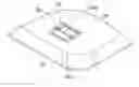
FIG. 1 is a partial, isometric view of an electronic device including a connecting mechanism in accordance with an exemplary embodiment, showing the connecting mechanism in a first state.
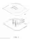
FIG. 2 is similar to FIG. 1, but showing the connecting mechanism in a second state.
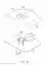
FIG. 3 is a schematic view of the connecting mechanism, in the first working state.
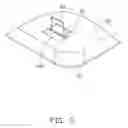
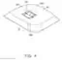
FIG. 4 is similar to FIG. 3, but showing the connecting mechanism in the second working state.
DETAILED DESCRIPTION
The disclosure, including the accompanying, is illustrated by way of example and not by way of limitation. It should be noted that references to “an” or “one” embodiment in this disclosure are not necessarily to the same embodiment, and such references mean at least one.
Referring to FIG. 1, in an exemplary embodiment, an electronic device 1 includes a first housing 10, a second housing 20, and a connecting mechanism 30 for connecting the first housing 10 and the second housing 20.
Referring to FIG. 2, the second housing 20 includes a recessed portion 201 defining a slot 202 and two holes 203 at opposite ends of the slot 202. The two holes 203 communicate with the slot 202.
The connecting mechanism 30 includes two fixing elements 31 fixed on the first housing 10, two rings 32, and a movable element 33. Each fixing element 31 can be a substantially arch shaped, and includes a curved connecting portion 312 and two substantially parallel fixing portions 311. One end of each fixing portion 311 is connected to one end of the connecting portion 312, and another end is fixed to the first housing 10, thereby fixing the fixing element 31 to the first housing 10. The movable element 33 is substantially a square frame, and includes four rounded corners 331. In the embodiment, the movable member 33 is substantially rectangular. The movable element 33 is connected to the two fixing elements 31 via the two rings 32, and can move freely between a substantially horizontal orientation and a substantially vertical orientation. The outer diameter of each ring 32 is greater than the diameter of the hole 203. The width of the movable element 33 equals to the sum of the outer diameter of the ring 32 and the length of the slot 202.
Referring to FIGS. 3-4, when attempting to connect the first housing 10 to the second housing 20, the movable element 33 is first orientated to be substantially vertical. The second housing 20 is then moved to cause the movable element 33 to pass through the slot 202 until part of each of the two rings 32 is received in the hole 203. Because the outer diameter of each ring 32 is greater than the diameter of the hole 203, the ring 32 cannot pass through the hole 203. The movable element 33 is then moved relative to the two rings 32 to prevent the two rings 32 from disengaging from the second housing 20 and rests on the bottom of the recessed portion 201, thereby connecting the first housing 10 to the second housing 20. In order to strengthen the connection between the first housing 10 and the second housing 20, the user can move the movable element 33 until the two rings 32 are located at the middle of opposite sides of the movable element 33.
Although the present disclosure has been specifically described on the basis of the embodiments thereof, the disclosure is not to be construed as being limited thereto. Various changes or modifications may be made to the embodiments without departing from the scope and spirit of the disclosure.
Claims
What is claimed is:1. A connecting mechanism for connecting a first housing and a second housing together, the second housing defining a slot and two holes at opposite ends of the slot and communicating with the slot, the connecting mechanism comprising:
two fixing elements fixed on the first housing;
two rings; and
a movable element connected to the two fixing elements through the two rings and capable of moving between a substantially horizontal orientation and a substantially vertical orientation;
wherein, to connect the first housing and the second housing together, the movable element is first orientated to be substantially vertical, the second housing is then moved to cause the movable element to pass through the slot until part of each of the two rings is received in one of the two holes, the movable element is moved relative to the two rings to prevent the two rings from disengaging from the second housing.
2. The connecting mechanism as described in claim 1, wherein each of the two fixing elements is substantially arch shaped.
3. The connecting mechanism as described in claim 2, wherein each of the two fixing elements comprises a curved connection portion and two substantially parallel fixing portions, one end of each fixing portion is connected to one end of the connection portion, and another end is fixed to the first housing.
4. The connecting mechanism as described in claim 2, wherein the movable element is a substantially square frame, and comprises four rounded corners.
5. The connecting mechanism as described in claim 1, wherein the outer diameter of each ring is greater than the diameter of each of the two holes.
6. The connecting mechanism as described in claim 1, wherein the width of the movable element equals to the sum of the outer diameter of the ring and the length of the slot.
7. An electronic device comprising:
a first housing;
a second housing defining a slot and two holes at opposite ends of the slot and communicating with the slot; and
a connecting mechanism configured for connecting the first housing and the second housing together, and the connecting mechanism comprising:
two fixing elements fixed on the first housing;
two rings; and
a movable element connected to the two fixing elements through the two rings and callable of moving between a substantially horizontal orientation and a substantially vertical orientation;
wherein, to connect the first housing and the second housing together, the movable element is first orientated to be substantially vertical, the second housing is then moved to cause the movable element to pass through the slot until part of each of the two rings is received in one of the two holes, the movable element is moved relative to the two rings to prevent the two rings from disengaging from the second housing.
8. The connecting mechanism as described in claim 7, wherein each of the two fixing elements is substantially arch shaped.
9. The connecting mechanism as described in claim 8, wherein each of the two fixing elements comprises a curved connection portion and two substantially parallel fixing portions, one end of each fixing portion is connected to one end of the connection portion, and another end is fixed to the first housing.
10. The connecting mechanism as described in claim 7, wherein the movable element is a substantially square frame, and comprises four rounded corners.
11. The connecting mechanism as described in claim 7, wherein the outer diameter of each ring is greater than the diameter of each of the two holes.
12. The connecting mechanism as described in claim 7, wherein the width of the movable element equals to the sum of the outer diameter of the ring and the length of the slot.
Images & Drawings included:
Sources:
- United States Patent and Trademark Office - verify current appl. status at the USPTO↗
Similar patent applications:
Recent applications in this class:
- » 20250223984 2025-07-10
Fastener for a Round Hole and a Slot - » 20250188968 2025-06-12
CLIP - » 20250172165 2025-05-29
CLIP STRUCTURE - » 20240229841 2024-07-11
FASTENING APPARATUS - » 20240200588 2024-06-20
Clip Retainers for Rib Attachment - » 20240141935 2024-05-02
FASTENER STRUCTURE - » 20230392628 2023-12-07
Fastener - » 20230220860 2023-07-13
Fastener Clip Assembly with Locking Arms - » 20230151836 2023-05-18
FASTENER STRUCTURE AND METHOD OF USE AND ASSEMBLY METHOD THEREOF - » 20230003240 2023-01-05
Fastening apparatus
Recent applications for this Assignee:
- » 20140233961 2014-08-21
Optical communication module including optical-electrical signal converters and optical signal generators - » 20140083669 2014-03-27
HEAT SINK - » 20140063746 2014-03-06
Electronic device with heat dissipation assembly - » 20140061224 2014-03-06
AUTOMATIC VENDING MACHINE - » 20140060914 2014-03-06
Enclosure with shield apparatus - » 20140058727 2014-02-27
MULTIMEDIA RECORDING SYSTEM AND METHOD - » 20140055955 2014-02-27
Fastener - » 20140055322 2014-02-27
DISPLAY SYSTEM AND HEAD-MOUNTED DISPLAY APPARATUS - » 20140054439 2014-02-27
CONTAINER DATA CENTER WITH SUPPORTING APPARATUS - » 20140054311 2014-02-27
AUTOMATIC VENDING MACHINE WITH MOVING MEMBER FOR PRODUCTS