Electrical machine with guide bars for facilitating assembly and a method for assembling the electrical machine
US20110273045A1
2011-11-10
13/102,519
2011-05-06
✅ Patent granted
US 8,841,815 B2
2014-09-23
-
-
Michael Andrews
Birch, Stewart, Kolasch & Birch, LLP
2031-10-03
Abstract:
A method for installing a rotor of an electrical machine is disclosed. The method comprises using axially directed guide bars (107-109) for keeping the rotor (102) centered with respect to a bore of a stator (101) during the installation of the rotor. The rotor has sliding surfaces so that it can be slid in the axial direction to its final position along the guide bars. The mechanical support structure (104) that supports bearings (105, 106) of the rotor are provided with supporting surfaces for being able to give mechanical support to the guide bars. The mechanical support structure (104) may comprise for example threaded holes to which threaded ends of the guide bars can be tightened. After the rotor has been moved to its final position and it is supported by the bearings, the guide bars are removed.
Inventors:
- Jorma MUSTALAHTI 79 🇫🇮 Hyvinkaa, Finland
- Jari TOIKKANEN 6 🇫🇮 Muurame, Finland
- Jorma TIRKKONEN 6 🇫🇮 Jyvaskyla, Finland
- Tuomas VUOLLE-APIALA 6 🇫🇮 Jyvaskyla, Finland
- Ville Pakarinen 2 🇫🇮 Jyvasklya, Finland
- Olli Liukkonen 4 🇫🇮 Lappeenranta, Finland
- Ilkka Martikainen 4 🇫🇮 Lappeenranta, Finland
- Jorma Tirkkonen 1 🇫🇮 Juväskylä, Finland
Assignee:
- MOVENTAS GEARS OY 18 🇫🇮 Jyvaskyla, Finland
- THE SWITCH DRIVE SYSTEMS OY 11 🇫🇮 Lappeenranta, Finland
- MOVENTAS WIND OY 4 🇫🇮 Jyvaskyla, Finland
- THE SWITCH DRIVE SYSTEM OY 1 🇫🇮 Lappeenranta, Finland
Applicant:
Interested in similar patents?
Get notified when new applications in this technology area are published.
Classification:
H02K15/16 » CPC main
Methods or apparatus specially adapted for manufacturing, assembling, maintaining or repairing of dynamo-electric machines Centering rotors within the stator; Balancing rotors
Y10T29/49009 » CPC further
Metal working; Method of mechanical manufacture; Electrical device making Dynamoelectric machine
Y10T29/49012 » CPC further
Metal working; Method of mechanical manufacture; Electrical device making; Dynamoelectric machine Rotor
H02K15/00 IPC
Methods or apparatus specially adapted for manufacturing, assembling, maintaining or repairing of dynamo-electric machines
H02K15/03 » CPC further
Methods or apparatus specially adapted for manufacturing, assembling, maintaining or repairing of dynamo-electric machines of stator or rotor bodies having permanent magnets
H02K5/1735 » CPC further
Casings; Enclosures; Supports; Casings or enclosures characterised by the shape, form or construction thereof; Means for supporting bearings, e.g. insulating supports or means for fitting bearings in the bearing-shields using bearings with rolling contact, e.g. ball bearings radially supporting the rotary shaft at only one end of the rotor
H02K5/22 IPC
Casings; Enclosures; Supports; Casings or enclosures characterised by the shape, form or construction thereof Auxiliary parts of casings not covered by groups -, e.g. shaped to form connection boxes or terminal boxes
H02K1/30 » CPC further
Details of the magnetic circuit characterised by the shape, form or construction; Rotating parts of the magnetic circuit; Means for mounting or fastening rotating magnetic parts on to, or to, the rotor structures using intermediate parts, e.g. spiders
H02K5/173 IPC
Casings; Enclosures; Supports; Casings or enclosures characterised by the shape, form or construction thereof; Means for supporting bearings, e.g. insulating supports or means for fitting bearings in the bearing-shields using bearings with rolling contact, e.g. ball bearings
Description
FIELD OF THE INVENTION
The invention relates to an electrical machine and to a method for assembling the electrical machine. More particularly, the method relates to installing the rotor of the electrical machine into the bore of the stator of the electrical machine.
BACKGROUND
Sometimes an electrical machine may have to be assembled or repaired at its site of normal operation, i.e. in the field conditions. For example, it may be a case that e.g. bearings of the electrical machine have to be changed and it may be too cumbersome and/or costly to move the whole electrical machine to be repaired elsewhere. Especially, installing a rotor of an electrical machine into the bore of the stator core may be a cumbersome task in field conditions. Especially, assembling a permanent magnet electrical machine may be a challenging task even in workshop circumstances because strong forces caused by the permanent magnets complicate the installation of a rotor including the permanent magnets into the bore of the stator core. In conjunction with permanent magnet electrical machines having surface mounted permanent magnets, there is a considerable risk of damaging the permanent magnets when installing the rotor into the bore of the stator core.
Publications CN101577453, JP2003143786, KR20000007669, JP8168215, and JP2223342 disclose various methods for installing permanent magnets into a rotor of a permanent magnet electrical machine. The installing of the permanent magnets into the rotor into correct positions is a challenging task because of the forces caused by the permanent magnets. However, technical solutions are needed also for overcoming the challenges related to installing of a rotor comprising permanent magnets into the bore of the stator core of a permanent magnet electrical machine. As well, the technical solutions are needed for overcoming the challenges related to installing of a rotor into the bore of the stator core of an electrically magnetized electrical machine in field conditions.
SUMMARY
In accordance with the first aspect of the present invention, there is provided a new method for assembling an electrical machine that comprises:
-
- a stator comprising a laminated stator core and stator windings,
- a rotor, and
- a mechanical support structure comprising bearings for supporting the rotor with respect to the stator.
The method for assembling the above-described electrical machine comprises:
-
- placing first ends of guide bars to the mechanical support structure so that the guide bars become axially directed,
- placing the rotor so that the rotor is capable of being slid along the axially directed guide bars,
- sliding the rotor along the guide bars in the axial direction into a bore of the stator core, the guide bars keeping the rotor centered relative to the bore of the stator core when the rotor is being slid in the axial direction, and
- removing the guide bars from the electrical machine.
As the guide bars are able to keep the rotor centered with respect to the bore of the stator core when the rotor is being slid in the axial direction into the bore of the stator core, the installation of the rotor is a straightforward operation also in field conditions. The method provides advantages especially in conjunction with permanent magnet electrical machines, where forces caused by permanent magnets complicate the installation of the rotor into the bore of the stator core. The risk of damaging the permanent magnets during the installation of the rotor is significantly reduced or even eliminated because the guide bars keep the rotor centered relative to the bore of the stator core. The axial direction mentioned above is the direction of the rotational axis of the rotor.
In accordance with the second aspect of the present invention, there is provided a new electrical machine the rotor of which can be installed using the above-described method. The electrical machine according to the second aspect of the invention comprises:
-
- a stator comprising a laminated stator core and stator windings,
- a rotor, and
- a mechanical support structure comprising bearings for supporting the rotor with respect to the stator,
wherein the mechanical support structure comprises supporting surfaces suitable for supporting axially directed guide bars and the rotor comprises sliding surfaces suitable for allowing the rotor to be installed into a bore of the stator core by sliding the rotor in an axial direction along the guide bars which, during the installation, are capable of keeping the rotor sufficiently centered relative to the bore of the stator core.
The electrical machine can be, for example, a permanent magnet electrical machine wherein the rotor comprises permanent magnets.
A number of exemplifying embodiments of the invention are described in accompanied dependent claims.
Various exemplifying embodiments of the invention both as to constructions and to methods of operation, together with additional objects and advantages thereof, will be best understood from the following description of specific exemplifying embodiments when read in connection with the accompanying drawings.
The verb “to comprise” is used in this document as an open limitation that neither excludes nor requires the existence of unrecited features. The features recited in dependent claims are mutually freely combinable unless otherwise explicitly stated.
BRIEF DESCRIPTION OF THE FIGURES
The exemplifying embodiments of the invention and their advantages are explained in greater detail below in the sense of examples and with reference to the accompanying drawings, in which:
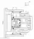
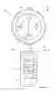
FIG. 1a shows a schematic section view of an electrical machine according to an embodiment of the invention in a situation in which a rotor is being installed,
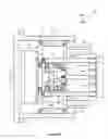
FIG. 1b shows a schematic section view of the electrical machine shown in FIG. 1a in a situation in which the rotor has been installed,
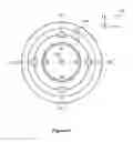
FIG. 1c shows a view of the section taken along the line A-A shown in FIG. 1a,
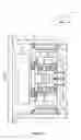
FIG. 1d shows a rotor of an electrical machine according to an embodiment of the invention,
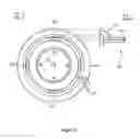
FIG. 2 illustrates guide bars having a different cross-section than those shown in FIG. 1c, and
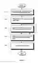
FIG. 3 shows a flow-chart of a method according to an embodiment of the invention for assembling an electrical machine.
DESCRIPTION OF THE EMBODIMENTS
FIG. 1a shows a schematic section view of an electrical machine according to an embodiment of the invention in a situation in which a rotor is being installed and FIG. 1b shows a schematic section view of the electrical machine in a situation in which the rotor is in its final position. FIG. 1c shows a view of the section taken along the line A-A shown in FIG. 1a. In FIGS. 1a-1c, the axial direction is the direction of the z-axis of the coordinate system 150. The electrical machine comprises a stator 101 that includes a laminated stator core and stator windings. The rotor 102 of the electrical machine comprises a frame 113 and permanent magnets 103 that are attached to the frame 113. The electrical machine comprises a mechanical support structure 104 comprising bearings 105 and 106 arranged to support the rotor with respect to the stator when the rotor has been installed to its normal position as shown in FIG. 1b. In the exemplifying construction shown in FIGS. 1a-1c, the mechanical support structure 104 is connected to (or is a part of) a frame structure of a gear stage 114 integrated with the electrical machine. The gear stage can be e.g. a planet gear stage. It should be, however, noted that from the viewpoint of the principle of the present invention it is immaterial whether or not there is any integrated gear stage. For example, the mechanical support structure 104 could as well be directly attached to an outer frame 115. The bearings shown in FIGS. 1a and 1b are rolling bearings. It should be, however, noted that any of the bearings could be a sliding bearing as well.
The mechanical support structure 104 comprises supporting surfaces suitable for supporting axially directed guide bars 107, 108, 109 and 110. In the exemplifying construction shown in FIGS. 1a-1c, the mechanical support structure 104 comprises threaded holes into which the treaded ends of the guide bars can be tightened. FIG. 1a shows only the guide bars 107-109, but FIG. 1c shows cross sections of all the guide bars 107-110. The rotor 102 comprises sliding surfaces suitable for allowing the rotor to be installed into a bore of the stator core by sliding the rotor in the direction of an arrow 120, i.e. the axial direction, along the guide bars which, during the installation, are capable of keeping the rotor sufficiently centered relative to the bore of the stator core. In the exemplifying construction shown in FIGS. 1a-1c, the frame 113 comprises apertures for the guide bars. In the situation shown in FIG. 1a, the surfaces of the apertures face towards the guide bars and thereby the surfaces of the apertures represent the sliding surfaces of the rotor. A support element 111 can be used to keep the ends of the guide bars at pre-determined positions with respect to each other so as to further improve the ability of the guide bars to keep the rotor centered relative to the bore of the stator core.
The principle of using the guide bars for assisting the installation of the rotor can be implemented with various mechanical arrangements. For example, it is not necessary to provide the mechanical support structure 104 with the threaded holes or with other cavities for the ends of the guide bars. The guide bars are sufficiently supported also, for example, in a case in which there are axially directed grooves on the surface of the mechanical support structure as illustrated in FIG. 1a-1c and the support element 111 is used. Furthermore, as illustrated in FIG. 1d, the inner walls of the frame 113 can be provided with e.g. projections 130 having axially directed grooves 131 which, together with corresponding axially directed grooves in the mechanical support structure 104, form channels for the guide bars and thereby support the guide bars.
The above illustrated principle of using the guide bars for assisting the installation of the rotor is advantageous since the guide bars are supported by the same mechanical support structure 104 that is used for arranging the bearings of the rotor. Thus, the guidance for the installation can be co-centric with the bearings 105 and 106 of the rotor.
The guide bars 107-110 which are used for supporting the rotor during installation can also be used for locking the rotor 102 in a fixed position with respect to the stator 101 for example during transportation of the electrical machine, i.e. the guide bars can be used as a transportation support for protecting the electrical machine during transportation e.g. shipping.
In the exemplifying cases described above, the guide bars 107-110 have a circular cross section. FIG. 2 illustrates a case in which there are guide bars 207, 208, 209, and 210 having a non-circular cross section. As illustrated in a partial side section view 200, the mechanical support structure 104 may comprise a cavity or cavities for receiving the ends of the guide bars.
In the exemplifying construction illustrated in FIGS. 1a-1c, the rotor comprises a separate center part 112 to which the frame 113 of the rotor is attached as shown in FIG. 1b. It should be, however, noted that the frame 113 and the center part 112 could also be a single, monolithic piece. Furthermore, as evident to a skilled person, the above-described principle of using guide bars for keeping the rotor centered with respect to the bore of the stator core during installation can be applied in conjunction with many different constructions of electrical machines. FIGS. 1a-1d relate to a case where the electrical machine is a permanent magnet electrical machine. However, as evident to a skilled person, the electrical machine does not necessarily have to be a permanent magnet electrical machine. Despite the above-described principle based on the guide bars provides most of its advantages in conjunction with permanent magnet electrical machines, this principle is applicable also with electrically magnetized electrical machines.
FIG. 3 shows a flow-chart of a method according to an embodiment of the invention for assembling an electrical machine that comprises:
-
- a stator comprising a laminated stator core and stator windings,
- a rotor, and
- a mechanical support structure comprising bearings for supporting the rotor with respect to the stator.
The method comprises:
-
- placing, in the method phase 301, first ends of guide bars to the mechanical support structure so that the guide bars become axially directed,
- placing, in the method phase 302, the rotor so that the rotor is capable of being slid along the axially directed guide bars,
- sliding, in the method phase 304, the rotor along the guide bars in the axial direction into a bore of the stator core, the guide bars keeping the rotor centered relative to the bore of the stator core when the rotor is being slid in the axial direction, and
- removing, in the method phase 305, the guide bars from the electrical machine.
In a method according to an embodiment of the invention, the first end of each guide bar is pushed into a cavity of the mechanical support structure.
In a method according to an embodiment of the invention, the first end of each guide bar is threaded and is tightened into a corresponding threaded hole of the mechanical support structure.
A method according to an embodiment of the invention further comprises placing, in the optional method phase 303, a support element to second ends of the guide bars for keeping the second ends of the guide bars at pre-determined positions with respect to each other so as to further improve the ability of the guide bars to keep the rotor centered relative to the bore of the stator core.
In a method according to an embodiment of the invention, the rotor comprises permanent magnets.
There is also provided a new method for providing an electrical machine with a transportation support, the electrical machine comprising:
-
- a stator comprising a laminated stator core and stator windings,
- a rotor, and
- a mechanical support structure comprising bearings for supporting the rotor with respect to the stator.
The method for providing the electrical machine with the transportation support comprises:
-
- placing first ends of guide bars to the mechanical support structure so that the guide bars become extending in the axial direction through apertures of the rotor so as to lock the rotor in a fixed position with respect to the stator.
The specific examples provided in the description given above should not be construed as limiting. Therefore, the invention is not limited merely to the embodiments described above.
Claims
What is claimed is:1. An electrical machine comprising:
a stator comprising a laminated stator core and stator windings,
a rotor, and
a mechanical support structure comprising bearings for supporting the rotor with respect to the stator,
wherein the mechanical support structure comprises supporting surfaces suitable for supporting axially directed guide bars and the rotor comprises sliding surfaces suitable for allowing the rotor to be installed into a bore of the stator core by sliding the rotor in an axial direction along the guide bars which, during the installation, are capable of keeping the rotor centered relative to the bore of the stator core.
2. An electrical machine according to claim 1, wherein the mechanical support structure comprises a cavity or cavities for receiving ends of the guide bars.
3. An electrical machine according to claim 1, wherein the mechanical support structure comprises threaded holes for receiving treaded ends of the guide bars.
4. An electrical machine according to claim 1, wherein the rotor comprises permanent magnets.
5. A method for assembling an electrical machine that comprises:
a stator comprising a laminated stator core and stator windings,
a rotor, and
a mechanical support structure comprising bearings for supporting the rotor with respect to the stator,
the method comprising:
placing first ends of guide bars to the mechanical support structure so that the guide bars become axially directed,
placing the rotor so that the rotor is capable of being slid along the axially directed guide bars,
sliding the rotor along the guide bars in the axial direction into a bore of the stator core, the guide bars keeping the rotor centered relative to the bore of the stator core when the rotor is being slid in the axial direction, and
removing the guide bars from the electrical machine.
6. A method according to claim 5, wherein the first end of each guide bar is pushed into a cavity of the mechanical support structure.
7. A method according to claim 5 wherein the first end of each guide bar is threaded and is tightened into a threaded hole of the mechanical support structure.
8. A method according to claim 5, wherein the method further comprises placing a support element to second ends of the guide bars for keeping the second ends of the guide bars at pre-determined positions with respect to each other so as to further improve the ability of the guide bars to keep the rotor centered relative to the bore of the stator core.
9. A method according to claim 5, wherein the rotor comprises permanent magnets.
Images & Drawings included:
Sources:
- United States Patent and Trademark Office - verify current appl. status at the USPTO↗
Recent applications in this class:
- » 20250119040 2025-04-10
ASSEMBLY OF A ROTOR OF A GENERATOR OF A WIND TURBINE - » 20240333113 2024-10-03
MOTOR AND METHOD OF MANUFACTURING THE SAME - » 20240235348 2024-07-11
ALIGNMENT SYSTEM FOR STATOR CORE - » 20240048032 2024-02-08
GENERATOR ROTOR CENTERING JIG - » 20240022149 2024-01-18
ELECTRICAL MACHINE ARRANGEMENT - » 20230034019 2023-02-02
Fixing device for electric motor - » 20220416632 2022-12-29
ROTARY DRIVE DEVICE AND MANUFACTURING METHOD THEREOF - » 20220352798 2022-11-03
Air gap adjustment apparatus - » 20210313866 2021-10-07
System for assembling a generator, generator vertical assembly device and corresponding assembling method - » 20200403488 2020-12-24
Motor assembly and manufacturing method thereof
Recent applications for this Assignee:
- » 20200336057 2020-10-22
Rotor of an induction machine and a method for assembling a cage winding of the rotor - » 20200263765 2020-08-20
Planetary gear - » 20200191256 2020-06-18
Planet wheel shaft for a planetary gear - » 20200083765 2020-03-12
Permanent magnet modules for an electric machine having axially and circumferentially offset permanent magnet elements, a rotor, permanent magnet electric machine, and a method for assembling thereof - » 20190136944 2019-05-09
Planet wheel assembly for a planetary gear - » 20180187719 2018-07-05
Planet wheel carrier for a planetary gear - » 20170331337 2017-11-16
Permanent magnet machine - » 20170253466 2017-09-07
HOIST TOOL FOR HANDLING A SHRINK ELEMENT OF A GEAR SYSTEM - » 20160298597 2016-10-13
Maintenance tool for a planetary gear - » 20150337946 2015-11-26
Gear unit and a method for heating lubricant oil of a gear unit