Method for the In-Line Processing of Liquid or Pasty or Semi-Liquid Media such as Grape Harvests
US20110296853A1
2011-12-08
13/201,799
2010-02-09
Abstract:
The invention relates to a method for the in-line processing of liquid or pasty or semi-liquid media or further, media which contain solid elements in a liquid base, in pipe for conveying the medium between two steps in a plant by direct injection of a cryogenic fluid into the pipe, characterized in that the method uses, for the injection into the pipe, an injection device including a hollow cylindrical body in which a valve urged by a spring is inserted, said injection device including a through-channel substantially parallel to said valve and supplied with a pressurized cryogenic fluid, wherein one end of the through-channel is connected to the cryogenic fluid supply system while the opposite end opens at the seat of the valve.
Inventors:
- Jo Algoet 4 🇧🇪 Wijtschate-Heuvelland, Belgium
- Carinne Kempen 3 🇫🇷 Viroflay, France
- Dominique Bras 2 🇫🇷 Tremblay En France, France
- Patrick Cazorla 1 🇫🇷 Cuges les Pins, France
Assignee:
- L'Air Liquide Societe Anonyme Pour L'Etude Et L'Exploitation Des Procedes Georges Claude 1,444 🇫🇷 Paris, France
Interested in similar patents?
Get notified when new applications in this technology area are published.
Classification:
A23B7/055 » CPC main
Preservation or chemical ripening of fruit or vegetables; Freezing; Subsequent thawing; Cooling with addition of chemicals or treatment with chemicals other than cryogenics, before or during cooling, e.g. in the form of an ice coating or frozen block with direct contact between the food and the chemical, e.g. liquid nitrogen, at cryogenic temperature
A23L3/365 » CPC further
Preservation of foods or foodstuffs, in general, e.g. pasteurising, sterilising, specially adapted for foods or foodstuffs; Freezing; Subsequent thawing; Cooling Thawing subsequent to freezing
B05B1/3073 » CPC further
Nozzles, spray heads or other outlets, with or without auxiliary devices such as valves, heating means designed to control volume of flow, e.g. with adjustable passages the control being effected by relative coaxial longitudinal movement of the controlling element and the spray head the controlling element being a deflector acting as a valve in co-operation with the outlet orifice
B05B1/323 » CPC further
Nozzles, spray heads or other outlets, with or without auxiliary devices such as valves, heating means designed to control volume of flow, e.g. with adjustable passages in which a valve member forms part of the outlet opening the valve member being actuated by the pressure of the fluid to be sprayed
B05B7/0892 » CPC further
Spraying apparatus for discharge of liquids or other fluent materials from two or more sources, e.g. of liquid and air, of powder and gas; Spray pistols; Apparatus for discharge with separate outlet orifices, e.g. to form parallel jets , to form intersecting jets the outlet orifices for jets constituted by a liquid or a mixture containing a liquid being disposed on a circle
C12G1/0213 » CPC further
Preparation of wine or sparkling wine; Preparation of must from grapes; Must treatment and fermentation with thermal treatment of the vintage
F25D3/10 » CPC further
Devices using other cold materials; Devices using cold-storage bodies using liquefied gases, e.g. liquid air
F25D25/00 IPC
Charging, supporting, and discharging the articles to be cooled
Description
The present invention relates to the field of the processing, for example chilling, inerting, carbonation or alternatively acid/base chemical reactions, of media (which can be liquid or semi-liquid or pasty media or alternatively media consisting of solid elements in a liquid base), in particular in the food industry, said processing taking place in line in pipes. By way of example, it particularly concerns the chilling of grape harvests (whole or crushed grapes) which takes place in the pipe connecting the harvesting stage to the press, but it can also be applied in an extremely advantageous manner to other media which need to be chilled, such as dairy media, or alternatively for the processing of waste water.
Let us now examine in more detail below the example of the chilling of grape harvests.
Users seek to chill whole or crushed grapes using a quick, harmonious and non-mechanical method in order to increase the likelihood of obtaining high-quality wines:
-
- by eliminating or considerably reducing the trituration phenomena on the fruit and the must;
- it is desirable to have grapes at a low temperature so that, from the beginning of the wine-making process, the start of the fermentation can be controlled or macerations can be performed at low temperature before fermentation;
- it is moreover known that fermentation which takes place at a lower temperature give a clearer and more aromatic wine and also makes it possible to reduce the quantity of SO2 used;
- the use of inert cryogenic fluids to effect this lowering of the temperature makes it possible to protect the medium against a possible oxidation, the negative consequences of which are also well known.
The literature records a number of methods and devices performing such a chilling, among which the following references may be mentioned:
-
- the document WO2004/03 7966, which describes the in-line injection of liquid CO2 into the pipe connecting the container that receives the grape harvest and the press, but this document employs a simple nozzle for injection into the pipe, which according to trials carried out by the Applicant do not make it possible to prevent pressure surges in the medium being processed (which according to the present invention it is desired to prevent). It should also be mentioned that such simple nozzles effect a highly imperfect distribution of the cryogenic fluid in the stream of grape harvest being transported. It may also be pointed out that it is with difficulty that such a simple nozzle can lower the temperature by more than 5° C. for a product flow rate of 70 to 80 tonnes/h.
- another type of system may also be mentioned, illustrated by the document WO 2005/05 3440, which uses a batch-type processing system which, although it is extremely advantageous and high-performing, is also more complex, heavier and more difficult to install on an existing plant.
It will be understood in the light of the above that according to the present invention an in-line processing system is sought which can be easily adapted to an existing plant and which makes it possible:
-
- using such a direct injection, to chill the product and in particular the grape harvest, by 5 to 10° C. relative to its initial temperature;
- to allow a flow rate of grape harvest of typically 80 tonnes/hour to be processed;
- to obtain good homogeneity of the temperature in the stream;
- not to adversely affect the product being processed by avoiding in particular any form of trituration of the grapes;
- to be able to easily employ or not employ the injection as necessary.
The invention thus relates to a method for the in-line processing of liquid or pasty or semi-liquid media or alternatively media consisting of solid elements in a liquid base, in a pipe transporting the medium between two stages of a plant, by the direct injection into the pipe of a cryogenic fluid, characterized in that, to perform the injection into the pipe, an injection device is used which comprises a hollow cylindrical body into which is inserted a valve loaded by a spring, said injection device comprising at least one through channel substantially parallel to said valve and intended to be supplied with pressurized cryogenic fluid, one end of said through channel being connected to the cryogenic fluid supply system and the opposite end opening out in the seat of the valve.
The advantages of the proposed solution can be summarized as follows:
-
- the injector can be integrated on a selected and independent specific pipe portion, for example between two flanges, to facilitate installation;
- the injector can be positioned such that the cryogenic fluid is injected into the axis of the pipe (into the axis of the movement of the product to be processed in the pipe);
- the trials carried out by the Applicant using such an in-line injector have shown a high degree of heat exchange between the product and the cryogenic fluid, a better distribution of the cryogenic fluid compared with what may be observed with a simple nozzle, hence resulting in a better homogenization of the temperature of the product;
- the response time of the system is short, thus making it possible to adapt very easily to variable inlet temperatures and/or product flow rates;
- the injection of cryogenic fluid can be perfectly controlled, for example by the use of a proportional valve, the opening/closing of the proportional valve being dependent on the difference between the reference temperature and the temperature measured in a downstream part of the pipe, for example;
- the chilling is performed under pressure and continuously, ensuring that there are no pressure surges in the pipe and hence no spoiling of the product.
It may be believed, without of course being bound by this explanation, that this satisfactory result is linked to the annular distribution of the CO2, obtained by the injector that is used and giving rise to a larger specific grape harvest/CO2 contact surface area, but it may also result from the fact that axial injection limits localized degassing so that it can be promoted in a more gradual fashion in the flow.
-
- the results observed in the case of the grape harvest moreover show that clear, non-cloudy juice is obtained, which is an indicator that oxidation phenomena have been controlled very well.
The invention will now be explained in more detail with the aid of a practical example, illustrated in the drawings, in which:
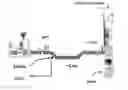
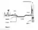
FIG. 1 is a partial diagrammatic view of a pipe connecting the stemmer to the press in a grape harvest-processing plant, and the positioning of an in-line CO2 injector in this pipe; and the injector according to the invention on the pipe connecting the harvesting stage to the press;
FIG. 2 is a view in section of an injector according to the invention;
FIG. 3 is a view in section in a perpendicular plane of this same injector;
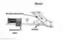
FIG. 4 shows a close-up of the zone in which an injector according to the invention is joined to the pipe transporting the product to be processed.
As can be seen more clearly in FIGS. 2 and 3, the injection device 3 comprises a body consisting of two integrally connected parts, the lower part 9 and the upper part 7. The upper part itself consists of three elements, a stainless-steel substantially cylindrical outer wall 14, one end of which bears indirectly against the lower part 9 and the other end of which is intended to be fixed on the wall of the vessel.
A complementarily shaped piece, which is also hollow and insulating and is termed a thermal bridge, is arranged inside this wall 14, a third stainless-steel element 16 being arranged inside said piece and traversed at its center by the valve 17 and by two through channels 18 opening out onto the beveled upper part of the piece 16 intended to receive the seat 13 of the valve 17.
The central through opening of the piece 16 comprises three zones, a central zone 19a with a diameter substantially equal to that of the valve such that the valve can be placed so as to slide in this zone, and a lower zone 19b with a greater diameter such that it can receive, around the axis of the valve, the spring 19 which loads the latter. This spring 19 is supported by the shoulder 20 formed between the zones 19a and 19b.
At the upper opposite end, the zone 19c has a beveled shape with a diameter that is wider at its free end, the shape of the bevel being adapted so as to receive leaktightly the seat of the valve when the valve is loaded by the spring.
The lower part 9 for its part consists of a single stainless-steel element with a cylindrical general shape. This piece has a blind central recess 21 which, when the device is mounted, coincides with the opening 19b of the upper part. This recess is intended to receive the end of the valve supported by the spring 19 and the calibrating nut 22 of the spring.
It also has, on either side of the blind recess, two vertical channels 23, 24 which, in the mounting position, each open out at one end into a through channel 18 and at the other end into a perpendicular channel 25, one end of which opens out into the channel 23 and the other is intended to be connected to the cryogenic fluid supply system via the connector 26.
The lower part 9 is fixed to the central piece 16 by screws 27 and 28.
The screw 28 is a one-way screw which makes it possible to comply with safety standards for pressurized devices.
The parts 14 and 15 are made integral with the part 9 by a connector (not shown), preferably a quick-release one but which could also be a screw-in, bayonet-type or similar connector.
During operation, the cryogenic fluid is charged into the device 3 through the channel 25 and then each of the channels 18. The pressurized fluid then exerts a pressure on the seat of the valve, a space then being formed between the part 19c and the seat of the valve.
It will be observed that it is very easy to disassemble and reassemble the injection unit 3. If the connector 10 is disassembled, the various constituent pieces can be separated so that they can be inspected and cleaned.
The injector is, for example, connected to the pipe by a clamp-type connector and, because the free end 8 is fixed, welded onto a portion of the pipe.
By way of example, a joint with a DN65-type diameter (76.1 mm) is produced.
FIG. 4 shows a close-up of the zone in which an injector according to the invention is joined to the pipe transporting the product to be processed.
Advantageously, the number of through channels 18 lies between 2 and 8 and more preferably is at least equal to 6.
Advantageously, their diameter is situated in the range between 2 and 6 mm.
According to one of the embodiments of the invention, the injector has six through channels which advantageously have a diameter close to 5 mm.
By way of illustration, examples of operating conditions are given below which have proved to be satisfactory for processing grape harvests.
-
- a flow rate for injected liquid CO2 which is close to 6000 kgLCO2/h and could, depending on circumstances, for example be situated in the range of 500 to 8000 kg/h of LCO2.
the range of pressure in the pipe typically ranges from 1 relative bar to 5 bar (and is commonly 1 bar).
-
- a range for the flow rate of liquid nitrogen between 700 l/h and 6000 l/h for a range of pressure from 1 relative bar to 5 bar can typically be envisaged.
Claims
1-4. (canceled)
5. A method for the in-line processing of a liquid, pasty, or semi-liquid media or a media comprising solid elements in a liquid base, comprising the step of directly injecting a cryogenic fluid from a cryogenic fluid supply system and into a pipe transporting the medium between two stages of a plant using an injection device comprising:
a hollow cylindrical body into which is inserted a valve loaded by a spring;
at least one through channel substantially parallel to said valve and adapted to be supplied with pressurized cryogenic fluid, one end of said through channel being connected to the cryogenic fluid supply system for and an opposite end of said through channel opening out in a seat of the valve.
6. The method of claim 5, wherein said at least one through channel comprises 2 to 8 through channels, said channels being arranged symmetrically relative to a longitudinal axis of the valve.
7. The method of claim 5, wherein:
a portion of said injection device is connected to said pipe; and
the injection device comprises a thermal bridge made of insulating material disposed between said at least one channel and the portion of the injection device connected to the pipe.
8. The method of claim 5, wherein said injection device further comprises:
a lower element which, in an operating position, is furthest from the pipe and which is connected to the cryogenic fluid supply system, said lower element comprising at least one supply pipe a first end of which is linked to the cryogenic fluid supply system, a central blind recess;
a central element, a lower end of the central element bearing against the lower element, the central element having a through hole formed axially therein, said at least one through channel extending through said lower and central elements, a second end of said lower element supply pipe being linked to the portion of the at least one channel present in the central element;
a valve placed so as to slide in the central element through hole, a seat of the valve bearing against the beveled upper part of said through hole in leaktight fashion, a free shaft of the valve being received in the central blind recess of the lower element, the free shaft being surrounded by the spring, the central element through hole having a smaller diameter at an upper end thereof and a greater diameter at a lower end thereof, a shoulder being formed by an upper horizontal surface of the greater diameter portion such that the spring is supported against the shoulder;
a thermal bridge surrounding the central element and a lower end of which bears against the lower element; and
a wall element, a lower end of which bears against the lower edge of the thermal bridge and an upper end of which is fixed to the pipe.
9. The method of claim 5, wherein the media comprises solid elements in a liquid base, the solid elements being grapes.
10. The method of claim 9, wherein the media is chilled by 5 to 10° C. relative to a temperature of the media prior to said injection of cryogenic fluid.
11. The method of claim 5, wherein the cryogenic fluid is injected into the pipe in a direction of flow of the media through the pipe.
12. The method of claim 5, wherein a diameter of the at least one through channel is between 2 and 6 mm.
13. The method of claim 5, wherein the cryogenic fluid is liquid carbon dioxide, the liquid carbon dioxide being injected into the pipe at a flow rate of 500 to 8000 kg/hr.
14. The method of claim 5, wherein a pressure in the pipe is in a range of from 1 bar (relative) to 5 bar (relative).
15. The method of claim 5, wherein the cryogenic fluid is liquid nitrogen, the liquid nitrogen being injected into the pipe at a flow rate of between 700 l/hr and 6000 l/hr.
Images & Drawings included:

Sources:
- United States Patent and Trademark Office - verify current appl. status at the USPTO↗
Recent applications in this class:
- » 20240381885 2024-11-21
STONE FRUIT QUALITY - » 20240206485 2024-06-27
PASS-THROUGH SYSTEM FOR TREATMENT AND/OR COOLING OF PERISHABLE PRODUCTS AND METHODS OF USE THEREOF - » 20230371534 2023-11-23
Method and Apparatus for Preservation of Organic Products - » 20230043870 2023-02-09
LIQUID NITROGEN QUICK-FREEZING PRESERVATION METHOD FOR FRESH BAMBOO SHOOTS - » 20210368814 2021-12-02
Movable controlled atmosphere store for fruits and vegetables - » 20210212331 2021-07-15
Method for preserving fresh juice of citrus fruits and pomegranates - » 20160143303 2016-05-26
Method for preparing deep-frozen vegetables pieces - » 20140342064 2014-11-20
Refrigerator crisper and ozonation system and method - » 20110027439 2011-02-03
METHOD FOR FREEZING FRUIT AND VEGETABLE PRODUCE
Recent applications for this Assignee:
- » 20250166974 2025-05-22
SULFUR-CONTAINING MOLECULES FOR HIGH ASPECT RATIO PLASMA ETCHING PROCESSES - » 20250164074 2025-05-22
TANK FOR STORING LIQUEFIED GAS AND FLUID TRANSFER METHOD - » 20250162866 2025-05-22
METHOD FOR CRACKING AMMONIA - » 20250161976 2025-05-22
NEW LOW-K MATERIALS DERIVED BY HYDROSILYLATION AND METHODS OF USING THEM FOR DEPOSITION - » 20250155175 2025-05-15
REFRIGERATION DEVICE AND METHOD - » 20250154042 2025-05-15
MELTING DEVICE - » 20250149609 2025-05-08
FUEL CELL - » 20250137596 2025-05-01
VALVE FOR PRESSURIZED FLUID AND A CONTAINER OR A SET OF CONTAINERS FOR PRESSURIZED FLUID - » 20250129889 2025-04-24
METHOD AND DEVICE FOR TRANSFERRING CRYOGENIC FLUID - » 20250121315 2025-04-17
FACILITY FOR RECOVERING CO2 FROM A FEED GAS FLOW