System for using attributes to deploy demand response resources
US20110301774A1
2011-12-08
13/153,251
2011-06-03
✅ Patent granted
US 8,572,230 B2
2013-10-29
-
-
Wing F Chan | Tesfay Yohannes
Seager Tufte & Wickhem LLC.
2031-06-03
Abstract:
A system for using attributes to deploy demand response resources. A service provider may provide energy to customers. The provider may via interactions modify consumption of the energy by the customers. Customers that participate in these interactions may be regarded as demand response resources. Interactions may incorporate demand response signals sent to the resources at their respective facilities. Each resource may have a demand response client which has an association with a customer account in a demand response management system of the provider. The association may be regarded as a binding of the demand response client. The binding may involve inputting an attribute of the demand response client, which can be correlated to the customer account. The attribute may be, for example, a location of the demand response client. Such attribute may be used for the association of the demand response client with a proper customer account.
Assignee:
- HONEYWELL INTERNATIONAL INC. 10,240 🇺🇸 Morristown, NJ, United States
Applicant:
Interested in similar patents?
Get notified when new applications in this technology area are published.
Classification:
G06F1/26 IPC
Details not covered by groups - and Power supply means, e.g. regulation thereof
G06F16/90332 » CPC further
Information retrieval; Database structures therefor; File system structures therefor; Details of database functions independent of the retrieved data types; Querying; Query formulation Natural language query formulation or dialogue systems
G06Q50/06 » CPC further
Systems or methods specially adapted for specific business sectors, e.g. utilities or tourism Electricity, gas or water supply
H02J3/14 » CPC further
Circuit arrangements for ac mains or ac distribution networks for adjusting voltage in ac networks by changing a characteristic of the network load by switching loads on to, or off from, network, e.g. progressively balanced loading
H02J13/00026 » CPC further
Circuit arrangements for providing remote indication of network conditions, e.g. an instantaneous record of the open or closed condition of each circuitbreaker in the network; Circuit arrangements for providing remote control of switching means in a power distribution network, e.g. switching in and out of current consumers by using a pulse code signal carried by the network characterised by information or instructions transport means between the monitoring, controlling or managing units and monitored, controlled or operated power network element or electrical equipment using wireless data transmission involving a local wireless network, e.g. Wi-Fi, ZigBee or Bluetooth
H02J13/00028 » CPC further
Circuit arrangements for providing remote indication of network conditions, e.g. an instantaneous record of the open or closed condition of each circuitbreaker in the network; Circuit arrangements for providing remote control of switching means in a power distribution network, e.g. switching in and out of current consumers by using a pulse code signal carried by the network characterised by information or instructions transport means between the monitoring, controlling or managing units and monitored, controlled or operated power network element or electrical equipment involving the use of Internet protocols
H02J13/0075 » CPC further
Circuit arrangements for providing remote indication of network conditions, e.g. an instantaneous record of the open or closed condition of each circuitbreaker in the network; Circuit arrangements for providing remote control of switching means in a power distribution network, e.g. switching in and out of current consumers by using a pulse code signal carried by the network for single frequency AC networks characterised by transmission structure between the control or monitoring unit and the controlled or monitored unit with direct transmission between the control or monitoring unit and the controlled or monitored unit using radio means
H02J13/0079 » CPC further
Circuit arrangements for providing remote indication of network conditions, e.g. an instantaneous record of the open or closed condition of each circuitbreaker in the network; Circuit arrangements for providing remote control of switching means in a power distribution network, e.g. switching in and out of current consumers by using a pulse code signal carried by the network for single frequency AC networks characterised by transmission structure between the control or monitoring unit and the controlled or monitored unit with transmission using an intermediate treatment level between the control or monitoring unit and the controlled or monitored unit
H04L41/12 » CPC further
Arrangements for maintenance, administration or management of data switching networks, e.g. of packet switching networks Discovery or management of network topologies
H04L41/5064 » CPC further
Arrangements for maintenance, administration or management of data switching networks, e.g. of packet switching networks; Network service management, e.g. ensuring proper service fulfilment according to agreements characterised by the interaction between service providers and their network customers, e.g. customer relationship management Customer relationship management
Y02B70/3225 » CPC further
Technologies for an efficient end-user side electric power management and consumption; Systems integrating technologies related to power network operation and communication or information technologies for improving the carbon footprint of the management of residential or tertiary loads, i.e. smart grids as climate change mitigation technology in the buildings sector, including also the last stages of power distribution and the control, monitoring or operating management systems at local level Demand response systems, e.g. load shedding, peak shaving
Y02D10/00 » CPC further
Energy efficient computing, e.g. low power processors, power management or thermal management
Y02D10/00 » CPC further
Energy efficient computing, e.g. low power processors, power management or thermal management
Y04S20/222 » CPC further
Management or operation of end-user stationary applications or the last stages of power distribution; Controlling, monitoring or operating thereof; End-user application control systems Demand response systems, e.g. load shedding, peak shaving
Y04S40/00 » CPC further
Systems for electrical power generation, transmission, distribution or end-user application management characterised by the use of communication or information technologies, or communication or information technology specific aspects supporting them
G06Q10/06 » CPC main
Administration; Management Resources, workflows, human or project management, e.g. organising, planning, scheduling or allocating time, human or machine resources; Enterprise planning; Organisational models
Description
This application is a continuation-in-part of U.S. patent application Ser. No. 13/019,943, filed Feb. 2, 2011, and entitled “Demand Response Management System”, which claims the benefit of U.S. Provisional Patent Application No. 61/301,123, filed Feb. 3, 2010, and entitled “Demand Response Management System”. U.S. patent application Ser. No. 13/019,943, filed Feb. 2, 2011, is hereby incorporated by reference. U.S. Provisional Patent Application No. 61/301,123, filed Feb. 3, 2010, is hereby incorporated by reference.
This application is a continuation-in-part of U.S. patent application Ser. No. 12/834,841, filed Jul. 12, 2010, and entitled “A System for Providing Demand Response Services”, which claims the benefit of U.S. Provisional Patent Application No. 61/271,084, filed Jul. 17, 2009. U.S. patent application Ser. No. 12/834,841, filed Jul. 12, 2010, is hereby incorporated by reference. U.S. Provisional Patent Application No. 61/271,084, filed Jul. 17, 2009, is hereby incorporated by reference.
BACKGROUND
The present disclosure pertains to utility resources and particularly to assessment and distribution of the resources. More particularly, the disclosure pertains to beneficial management of resources and their loads.
SUMMARY
The disclosure reveals a system for using attributes to deploy demand response resources. A service provider may provide energy to customers. The provider may via interactions modify consumption of the energy by the customers. Customers that participate in these interactions may be regarded as demand response resources. Interactions may incorporate demand response signals sent to the resources at their respective facilities. Each resource may have a demand response client which has an association with a customer account in a demand response management system of the provider. The association may be regarded as a binding of the demand response client. The binding may involve inputting an attribute of the demand response client, which can be correlated to the customer account. The attribute may be, for example, a location of the demand response client. Such attribute may be used for the association of the demand response client with a proper customer account.
BRIEF DESCRIPTION OF THE DRAWING
FIG. 1 is a diagram of a demand response system for using attributes of a demand response client for deploying demand response resources; and
FIG. 2 is a diagram of a demand response resource deployment approach.
DESCRIPTION
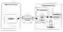
FIG. 1 is a diagram of a demand response system. Demand response (DR) may refer to interactions between one or more electric service providers 18, such as utilities and independent system operators (ISO's), and their customers at one or more facilities 14 for modifying their customers' electricity consumption (i.e., load profile). Electricity is just one example, among others, of an energy product provided for consumption by customers. The customers that participate in these interactions may be referred to as DR resources 19.
The interactions between a service provider 18 and its DR resources 19 may entail the service provider 18 using a demand response management system (DRMS) 13 to send a message (referred to as a “DR signal”) to a DR resource 19 at a customer facility 14. The DR signal may be delivered using a communications channel 17 such as the Internet, paging, and so forth. In order for the DR resource 19 to receive the DR signal, the DR resource 19 should have some sort of equipment (referred to as DR client 12) installed that is capable of communicating with the service provider's DRMS 13 using the communications channel 17.
One of the costly issues in deploying a DR client 12 may be the time and effort involved with associating the DR client 12 with a particular customer account within the service provider's DRMS 13. This association may be referred to as “binding” the DR client 12. Binding the DR client 12 may be important because binding allows the service provider 18 to send DR signals to a DR resource 19 that are specific to that DR resource 19.
Binding may entail inputting some attribute of the DR client 12 into the DRMS 13 that would allow sent DR signals to be routed to the DR client 12. A key is to find a set of one or more attributes which can be easily correlated to a customer account in the DRMS 13 in order to reduce manual data entry and thus save costs for time and effort. The present approach may use, for example, location attributes of DR client 12 to create the binding. The approach, with respect to a binding issue, may allow an easy-to-generate attribute of the DR client 12 (e.g., its location) to be used to associate the DR client 12 with the proper customer account in the DRMS 13.
When a DR client 12 is deployed in the field, it is possible to use a device that determines global positioning system (GPS) coordinates of the DR client 12. These coordinates may then be easily input and stored into the DR client 12 device itself in an automated fashion without a need for a manual data entry. The DR client 12 may then contact the DRMS 13 and send its location information, in addition to other information, to its network communications address. Customer accounts in the DRMS 13 may have attributes, such as an address and so on, that allow their customer locations to be known. Thus, when a DR client 12 contacts the DRMS 13 with its location, it may be automatically correlated to an existing customer account.
It is recognized that there may be some ambiguity between GPS location determined by an installer 11 and a customer's account. Therefore, an alternative to the procedure indicated herein may be to allow an installation technician (installer) 11 resolve those ambiguities by confirming the binding at the customer's site 14. This may be accomplished by presenting alternatives to the installer 11 to choose from or perhaps to allow some sort of browser-based internet application to be used. While the use of these techniques may add an extra burden on the installer 11, they might only be needed in a limited number of cases and may also insure that the correct binding is over a more manual data entry process.
The system as shown in FIG. 1 may incorporate, among other items, the service provider 18, the DRMS 13, the customer facility 14, the demand resource 19, the DR client 12, communications channel 17, some sort of installation or installer device (ID) 15 (used by an installer 11 of the equipment), and a communications technique 16. The following steps may be used to deploy the DR client 12: 1) The installation device 15 may be used by the installer 11 to automatically determine a current location of the DR client 12 using some sort of location-based technology such as a GPS; 2) Once the location is determined, this location may be input into the DR client 12 using any of a number of low cost communication techniques 16 incorporating a USB connection, Bluetooth, IR, and/or the like; 3) Once the location is entered into the DR client 12, then the DR client 12 may then contact the DRMS 13 via the communication channel 17 and send both its current location and its network address to the DRMS 13; and 4) The DRMS 13 may use the location of the DR client 12 to associate it with a specific customer account.
It may noted that in support of a use case where there are some ambiguities between the location of the installer 11 and the customer's account, the installation device 15 may contain a customer database (DB) that would allow the installer 11 to select a customer account from a limited set of customer accounts to bind to the DR client 12. Thus, the binding may be performed at the customer site 14 as opposed to at the DRMS 13.
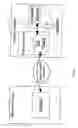
FIG. 2 is a flow diagram of a demand response resource deployment approach. The approach may incorporate providing 21 a service provider having a demand response management system, providing 22 a customer facility having a demand response resource, providing 23 power from the service provider to the demand response resource, interacting 24 the service provider with the demand response resource so as to modify power consumption by the demand response resource, providing 25 an attribute of a demand response resource to the demand response management system, and using 26 the demand response management system to correlate the attribute with a customer account and send a demand response signal to a customer as needed.
The approach may also incorporate binding 27 a demand response client. The demand response resource may incorporate the demand response client. The binding 27 the demand response client may permit the service provider to send demand response signals to the demand response resource which are specifically routed to that demand response resource.
The approach may also incorporate generating 28 a location of the customer facility from a device that determines geographical coordinates of the customer facility, and inputting 29 the location incorporating the geographical coordinates into the demand response client. The approach may additionally incorporate automatically correlating 30 the location to a customer at the demand response management system.
An application which is relevant to the present application is U.S. patent application Ser. No. 13/019,943, filed Feb. 2, 2011, and entitled “A Demand Response Management System”, which claims the benefit of U.S. Patent Provisional Patent Application No. 61/301,123, filed Feb. 3, 2010, and entitled “Demand Response Management System”. U.S. patent application Ser. No. 13/019,943, filed Feb. 2, 2011, is hereby incorporated by reference. U.S. Patent Provisional Patent Application No. 61/301,123, filed Feb. 3, 2010, hereby incorporated by reference.
An application which is relevant to the present application is U.S. patent application Ser. No. 12/834,841, filed Jul. 12, 2010, and entitled “A System for Providing Demand Response Services”, which claims the benefit of U.S. Provisional Patent Application No. 61/271,084, filed Jul. 17, 2009. U.S. patent application Ser. No. 12/834,841, filed Jul. 12, 2010, is hereby incorporated by reference. U.S. Provisional Patent Application No. 61/271,084, filed Jul. 17, 2009, is hereby incorporated by reference.
An application which is relevant to the present application is U.S. patent application Ser. No. 12/245,560, filed Oct. 3, 2008, and entitled “Critical Resource Notification System and Interface Device”, which claims the benefit of U.S. Provisional Patent Application No. 60/977,909, filed Oct. 5, 2007. U.S. patent application Ser. No. 12/245,560, filed Oct. 3, 2008, is hereby incorporated by reference. U.S. Provisional Patent Application No. 60/977,909, filed Oct. 5, 2007, is hereby incorporated by reference.
In the present specification, some of the matter may be of a hypothetical or prophetic nature although stated in another manner or tense.
Although the present system and/or approach has been described with respect to at least one illustrative example, many variations and modifications will become apparent to those skilled in the art upon reading the specification. It is therefore the intention that the appended claims be interpreted as broadly as possible in view of the prior art to include all such variations and modifications.
Claims
What is claimed is:1. A demand response system comprising:
a service provider;
a customer facility; and
a communications channel connected to the service provider and the customer facility; and
wherein the service provider identifies the customer facility by an attribute from the customer facility.
2. The system of claim 1, wherein:
the service provider comprises a demand response management system;
the customer facility comprises a demand response resource; and
wherein the attribute is provided from the demand response resource to the demand response management system.
3. The system of claim 2, wherein:
the attribute is associated with information in a customer account; and
a relationship of the attribute with the information creates a binding of the demand response resource with a customer account by the demand response management system.
4. The system of claim 3, wherein the binding permits the service provider to send demand response signals to the demand response resource which are specific to the demand response resource.
5. The system of claim 2, wherein:
the attribute comprises a location;
the location is of the demand response resource; and
the location is sent from the demand response resource to the demand response management system.
6. The system of claim 4, wherein the demand response management system correlates the location from the demand response resource with information in the customer account to provide an association of the demand response resource with the customer account.
7. The system of claim 1, further comprising:
an installation device situated at the customer facility; and
wherein:
the customer facility comprises a demand response resource;
the attribute comprises a location of the demand response resource; and
the installation device determines the location.
8. The system of claim 7, wherein:
the installation device comprises a customer database; and
a customer account is selected from the customer database to bind the demand response resource at the customer facility.
9. The system of claim 2, wherein:
the demand response resource comprises a demand response client;
an association of the demand response client with a customer account is a binding of the demand response client; and
the binding permits a service provider to send demand response signals specifically for the demand response client.
10. The system of claim 9, wherein:
binding comprises inputting the attribute of the demand response client into the demand response management system to allow demand response signals to be routed to the demand response client; and
the attribute may be correlated to a customer account.
11. The system of claim 9, wherein:
an attribute comprises a location of the demand response client and consequently the demand response resource;
a customer account has an address; and
the location may be correlated with the address.
12. The system of claim 9, further comprising:
an installation device situated at the customer facility; and
wherein the installation device determines a location of the demand response client and consequently the demand response resource.
13. The system of claim 12, wherein:
the installation device comprises a customer database; and
a customer account is selected from the customer database to bind the demand response resource at the customer facility.
14. A demand response resource deployment method comprising:
providing a service provider comprising a demand response management system;
providing a customer facility comprising a demand response resource;
providing power from the service provider to the demand response resource;
interacting the service provider with the demand response resource so as to modify power consumption by the demand response resource;
providing an attribute of a demand response resource to the demand response management system; and
using the demand response management system to correlate the attribute with a customer account and send a demand response signal to a customer as needed.
15. The method of claim 14, further comprising:
binding a demand response client; and
wherein:
the demand response resource comprises the demand response client; and
binding the demand response client permits the service provider to send demand response signals to the demand response resource which are specifically routed to that demand response resource.
16. The method of claim 14, further comprising:
generating a location of the customer facility from a device that determines geographical coordinates of the customer facility; and
inputting the location incorporating the geographical coordinates into the demand response client; and
wherein the location is automatically correlated to a customer at the demand response management system.
17. A demand response system for using an attribute to deploy a demand response resource, comprising:
a service provider; and
a demand response resource; and
wherein:
the service provider comprises a demand response management system;
the demand response resource comprises a demand response client;
the demand response client can communicate an attribute to the demand response management system; and
the demand response management system can correlate the attribute to a customer.
18. The system of claim 17, wherein correlating the attribute by the demand response management system to a customer comprises binding the demand response client.
19. The system of claim 18, wherein the binding entails inputting an attribute of a demand response client to permit the demand response signal being sent to be routed to the demand response client.
20. The system of claim 19, wherein:
the attribute comprises a location; and
the location is determined by a global positioning system device located at the demand response client.
Images & Drawings included:

Sources:
- United States Patent and Trademark Office - verify current appl. status at the USPTO↗
Similar patent applications:
Recent applications in this class:
- » 20250238734 2025-07-24
SYSTEM AND METHODS FOR TRANSPORTING END USERS - » 20250217726 2025-07-03
SYSTEMS AND METHODS FOR BEHAVIOURAL AND CONTEXTUAL DATA ANALYTICS - » 20250139539 2025-05-01
GENERATION OF EXECUTABLE PROCEDURE USING NATURAL LANGUAGE - » 20250077988 2025-03-06
SALES ASSISTANCE METHOD, SALES ASSISTANCE PROGRAM, AND SALES ASSISTANCE SYSTEM - » 20250013942 2025-01-09
SYSTEM AND METHOD FOR AUTOMATED CROSS-DOCK OPERATIONS - » 20250005465 2025-01-02
PROVIDING ACCESS TO A PRIVATE RESOURCE IN AN ENTERPRISE SOCIAL NETWORKING SYSTEM - » 20240428148 2024-12-26
MEDICATION WORKFLOW MANAGEMENT - » 20240420039 2024-12-19
COMPUTER-IMPLEMENTED METHOD, SYSTEM, AND APPARATUS FOR ELECTRONIC PATIENT CARE - » 20240394613 2024-11-28
COMPUTER-IMPLEMENTED SYSTEMS AND METHODS OF ANALYZING DATA IN AN AD-HOC NETWORK FOR PREDICTIVE DECISION-MAKING - » 20240378515 2024-11-14
GENERATION APPARATUS, GENERATION METHOD, DATA STRUCTURE OF MODEL DATA, DATA STRUCTURE OF RELATION DATA AND GENERATION PROGRAM
Recent applications for this Assignee:
- » 20200347311 2020-11-05
Process for natural gas production - » 20200222851 2020-07-16
Integrated mercaptan extraction and/or sweetening processes combined with thermal oxidation and flue gas treatment - » 20190174102 2019-06-06
Systems and methods for automatic video recording - » 20190136108 2019-05-09
STABILIZED IODOCARBON COMPOSITIONS - » 20190120659 2019-04-25
Differential hall magnet polarity detection for AMR 360 degree sensor - » 20190104161 2019-04-04
Systems and methods for directly accessing video data streams and data between devices in a video surveillance system - » 20190084905 2019-03-21
NOVEL PROCESS FOR MANUFACTURING 2-CHLORO-3,3,3-TRIFLUOROPROPENE FROM 1,2-DICHLORO-3,3,3-TRIFLUOROPROPENE - » 20190056529 2019-02-21
Anti-fog and anti-reflective dual-functional coating for optical articles - » 20190047927 2019-02-14
Methods for removing halogenated ethylene impurities in 2, 3, 3, 3-tetrafluoropropene product - » 20190005805 2019-01-03
Systems and methods for delaying or activating a blowout device or a purge device in a sampling pipe network of an aspirated smoke detection system