CABLE BINDING DEVICE
US20110314641A1
2011-12-29
12/859,289
2010-08-19
Abstract:
A cable binding device includes a tie for binding a first cable, and a cable clamp formed on the tie for binding a second cable.
Assignee:
- HON HAI PRECISION INDUSTRY CO., LTD. 12,828 🇹🇼 Tu-Cheng, Taiwan
Interested in similar patents?
Get notified when new applications in this technology area are published.
Classification:
B65D63/1027 » CPC main
Flexible elongated elements, e.g. straps, for bundling or supporting articles; Non-metallic straps, tapes, or bands; Filamentary elements, e.g. strings, threads or wires; Joints between ends thereof; Joints produced by application of integral securing members, e.g. buckles, wedges, tongue and slot, locking head and teeth or the like the integral securing member being formed as a female and male locking member, e.g. locking head and locking teeth, or the like
B65D63/00 IPC
Flexible elongated elements, e.g. straps, for bundling or supporting articles
Y10T24/14 » CPC further
Buckles, buttons, clasps, etc. Bale and package ties, hose clamps
Description
BACKGROUND
1. Technical Field
The present disclosure relates to a cable binding device.
2. Description of Related Art
Cable clamps or ties are used to position and organize cables of servers, otherwise the servers would be cluttered with cables and heat dissipation of the servers limited. Although ties can hold relatively more cables, they do not position and organize the cables as flexibly as cable clamps do. As a result, a cable binding device to overcome the above deficiencies is needed.
BRIEF DESCRIPTION OF THE DRAWINGS
Many aspects of the present embodiments can be better understood with reference to the following drawings. The components in the drawings are not necessarily drawn to scale, the emphasis instead being placed upon clearly illustrating the principles of the present embodiments. Moreover, in the drawings, all the views are schematic, and like reference numerals designate corresponding parts throughout the several views.
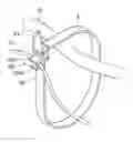
FIG. 1 is an isometric view of an exemplary embodiment of a cable binding device, together with a first cable and a second cable.
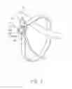
FIG. 2 is a similar view of the cable binding device of FIG. 1.
FIG. 3 is an isometric view of the cable binding device of FIG. 1 laid out straight.
DETAILED DESCRIPTION
The disclosure, including the accompanying drawings, is illustrated by way of example and not by way of limitation. It should be noted that references to “an” or “one” embodiment in this disclosure are not necessarily to the same embodiment, and such references mean at least one.
Referring to FIG. 1, an exemplary embodiment of a cable binding device is used to hold a first cable 10 and a second cable 12.
Referring to FIG. 2 and FIG. 3, the cable binding device includes a tie 3 and a cable clamp 32. A fastener 30 and an arrowhead-shaped extending portion 34 formed on opposite ends of the tie 3. A fastening hole 300 is defined in the fastener 30. The cable clamp 32 is formed on the tie 3, adjacent to the fastener 30.
The cable clamp 32 includes two parallel holding pieces 320 perpendicularly extending from the tie 3. A wedge-shaped blocking portion 3200 extends from a distal end of one of the holding pieces 320 toward the other holding piece 320.
Referring to FIG. 1 again, in use, the tie 3 is curled to form a circle for binding the first cable 10, with the cable clamp 32 located at an outer surface of the circle. The extending portion 34 of the tie 3 is engaged in the fastening hole 300 of the fastener 30. The second cable 12 is located between the holding pieces 320, blocked by the cable clamp 32, without disengaging from the cable clamp 32.
It is believed that the present embodiments and their advantages will be understood from the foregoing description, and they will be apparent that various changes may be made thereto without departing from the spirit and scope of the description or sacrificing all of their material advantages, the examples hereinbefore described merely being exemplary embodiment.
Claims
What is claimed is:1. A cable binding device, comprising:
a tie operable to circle to bind a first cable; and
a cable clamp formed on the tie to hold a second cable.
2. The cable binding device of claim 1, wherein a fastener is formed on a first end of the tie, an extending portion extends from a second end of the tie, to engage with the fastener in response to the tie being circled.
3. The cable binding device of claim 2, wherein the fastener defines a fastening hole to receive the extending portion.
4. The cable binding device of claim 1, wherein the cable clamp is formed adjacent to the fixing portion and located on an outer surface of the tie when the tie is circled.
5. The cable binding device of claim 4, wherein the cable clamp includes two opposite holding pieces substantially perpendicularly extending from the tie, a blocking portion extends from a distal end of one of the holding pieces toward the other holding piece.
Images & Drawings included:


Sources:
- United States Patent and Trademark Office - verify current appl. status at the USPTO↗
Similar patent applications:
- » 20130043355
CABLE BINDING DEVICE AND RACK USING THE SAME - » 20140377981
CABLE BINDING DEVICE - » 20210148488
Cable binding device - » 20090082821
Tightly binding device for bone joining cable - » 20060182406
Device and method for automatic connection and disconnection of the binding cables within a distributor
Recent applications in this class:
- » 20250074677 2025-03-06
SIZE-ADJUSTABLE FASTENER - » 20240286810 2024-08-29
LIGATION ASSEMBLY AND METHOD FOR USING THE SAME - » 20240239576 2024-07-18
Cable tie with two tooth shaped sides having enhanced tension - » 20240092546 2024-03-21
Fusible tie band - » 20240034530 2024-02-01
CABLE TIE - » 20240034529 2024-02-01
CABLE TIE - » 20230278766 2023-09-07
Cable tie - » 20230192376 2023-06-22
SELF-LOCKING TIE CORDS AND SYSTEMS, AND RELATED METHODS OF USE - » 20220332485 2022-10-20
Self-Threading Tie Having a Plurality of Holes - » 20220177206 2022-06-09
Releasable bundling tie
Recent applications for this Assignee:
- » 20140233961 2014-08-21
Optical communication module including optical-electrical signal converters and optical signal generators - » 20140083669 2014-03-27
HEAT SINK - » 20140063746 2014-03-06
Electronic device with heat dissipation assembly - » 20140061224 2014-03-06
AUTOMATIC VENDING MACHINE - » 20140060914 2014-03-06
Enclosure with shield apparatus - » 20140058727 2014-02-27
MULTIMEDIA RECORDING SYSTEM AND METHOD - » 20140055955 2014-02-27
Fastener - » 20140055322 2014-02-27
DISPLAY SYSTEM AND HEAD-MOUNTED DISPLAY APPARATUS - » 20140054439 2014-02-27
CONTAINER DATA CENTER WITH SUPPORTING APPARATUS - » 20140054311 2014-02-27
AUTOMATIC VENDING MACHINE WITH MOVING MEMBER FOR PRODUCTS