Heat sink wind guide structure and thermal module thereof
US20110315357A1
2011-12-29
12/824,439
2010-06-28
✅ Patent granted
US 8,893,769 B2
2014-11-25
-
-
Allen Flanigan | Jon T Schermerhorn
2031-11-16
Abstract:
A heat sink wind guide structure and a thermal module thereof. The heat sink wind guide structure includes a heat sink having multiple radiating fins and a wind incoming side. Each two adjacent radiating fins define therebetween a heat dissipation flow way in communication with the wind incoming side. The radiating fins include a first radiating fin and a second radiating fin, which are respectively positioned on two opposite outer sides of the heat sink. The first radiating fin has a first extension end and the second radiating fin has a second extension end. The heat sink is assembled with a fan to form the thermal module. By means of the first and second extension ends, the heat of the heat sink can be dissipated quickly and the heat dissipation airflow can be exhausted from many sides of the heat sink to greatly enhance heat dissipation efficiency.
Assignee:
- ASIA VITAL COMPONENTS CO., LTD. 36 🇹🇼 Taipei County, Taiwan
Applicant:
Interested in similar patents?
Get notified when new applications in this technology area are published.
Classification:
H01L2924/0002 » CPC further
Indexing scheme for arrangements or methods for connecting or disconnecting semiconductor or solid-state bodies as covered by; Technical content checked by a classifier Not covered by any one of groups , and
H01L2924/00 » CPC further
Indexing scheme for arrangements or methods for connecting or disconnecting semiconductor or solid-state bodies as covered by
F28F13/00 IPC
Arrangements for modifying heat-transfer, e.g. increasing, decreasing
F28F21/084 » CPC main
Constructions of heat-exchange apparatus characterised by the selection of particular materials of metal; Heat exchange elements made from metals or metal alloys from aluminium or aluminium alloys
F28D15/0233 » CPC further
Heat-exchange apparatus with the intermediate heat-transfer medium in closed tubes passing into or through the conduit walls ; Heat-exchange apparatus employing intermediate heat-transfer medium or bodies in which the medium condenses and evaporates, e.g. heat pipes the conduits having a particular shape, e.g. non-circular cross-section, annular
H01L23/427 » CPC further
Details of semiconductor or other solid state devices; Arrangements for cooling, heating, ventilating or temperature compensation ; Temperature sensing arrangements; Fillings or auxiliary members in containers or encapsulations selected or arranged to facilitate heating or cooling Cooling by change of state, e.g. use of heat pipes
F28F2250/08 » CPC further
Arrangements for modifying the flow of the heat exchange media , e.g. flow guiding means ; Particular flow patterns Fluid driving means, e.g. pumps, fans
F28F2215/00 » CPC further
Fins
F28F2255/16 » CPC further
Heat exchanger elements made of materials having special features or resulting from particular manufacturing processes extruded
F28F7/00 IPC
Elements not covered by group , or
H01L23/467 » CPC further
Details of semiconductor or other solid state devices; Arrangements for cooling, heating, ventilating or temperature compensation ; Temperature sensing arrangements involving the transfer of heat by flowing fluids by flowing gases, e.g. air
H01L23/3672 » CPC further
Details of semiconductor or other solid state devices; Arrangements for cooling, heating, ventilating or temperature compensation ; Temperature sensing arrangements; Selection of materials, or shaping, to facilitate cooling or heating, e.g. heatsinks; Cooling facilitated by shape of device Foil-like cooling fins or heat sinks
F24H3/02 IPC
Air heaters with forced circulation
H01L23/367 IPC
Details of semiconductor or other solid state devices; Arrangements for cooling, heating, ventilating or temperature compensation ; Temperature sensing arrangements; Selection of materials, or shaping, to facilitate cooling or heating, e.g. heatsinks Cooling facilitated by shape of device
F28F21/08 IPC
Constructions of heat-exchange apparatus characterised by the selection of particular materials of metal
F28D15/02 IPC
Heat-exchange apparatus with the intermediate heat-transfer medium in closed tubes passing into or through the conduit walls ; Heat-exchange apparatus employing intermediate heat-transfer medium or bodies in which the medium condenses and evaporates, e.g. heat pipes
F28F1/32 » CPC further
Tubular elements; Assemblies of tubular elements; Tubular elements and assemblies thereof with means for increasing heat-transfer area, e.g. with fins, with projections, with recesses the means being only outside the tubular element and extending transversely the means having portions engaging further tubular elements
Description
FIELD OF THE INVENTION
The present invention relates to a heat sink wind guide structure and a thermal module thereof, and more particularly to a thermal module with heat sink wind guide structure, in which the heat dissipation airflow is exhausted from many sides of the heat sink to greatly enhance heat dissipation efficiency.
BACKGROUND OF THE INVENTION
Following the advance of semiconductor technologies, the volume of integrated circuit has become smaller and smaller. In order to process more data, the current integrated circuit with the same volume contains several times more calculation components than the conventional integrated circuit. The larger the number of the calculation components contained in the integrated circuit is, the greater the heat generated by the calculation components in working. As exemplified with a common central processor, in a full-load state, the heat generated by the central processor may burn down the entire central processor. Therefore, heat dissipation of the integrated circuit has become a critical topic.
Please refer to FIG. 1, which is a perspective assembled view of a conventional thermal module 1. The conventional thermal module 1 is composed of a fan 11 and a cooperative heat sink 12. The fan 11 is mated with one side of the heat sink 12. The heat sink 12 has multiple radiating fins 121 defining therebetween multiple heat dissipation flow ways 122. The fan 11 has a wind exit side 111 adapted to the heat dissipation flow ways 122.
Two ends of the heat dissipation flow way 122 between the radiating fins 121 are open. In operation, the fan 11 forcedly guides heat dissipation airflow 2 to dissipate heat from the heat sink 12. The heat dissipation airflow 2 goes from the wind exit side 111 into the heat dissipation flow ways 122. Then the heat dissipation airflow 2 is exhausted from two ends of the heat dissipation flow ways 122 to achieve heat dissipation effect. However, the heat dissipation airflow 2 can only flow out from two sides of the heat sink 12. Therefore, the heat dissipation efficiency is quite limited and the heat may accumulate in the heat sink 12 to lower the heat dissipation effect. Moreover, such thermal module 1 is only applicable to one single heat source. Accordingly, the conventional thermal module 1 has the following shortcomings:
- 1. The heat dissipation efficiency of the conventional thermal module is low.
- 2. The heat is likely to accumulate in the heat sink of the conventional thermal module.
- 3. The heat dissipation effect of the conventional thermal module is poor.
SUMMARY OF THE INVENTION
A primary object of the present invention is to provide a heat sink wind guide structure, in which the heat dissipation airflow is exhausted from many sides of the heat sink to greatly enhance heat dissipation efficiency.
A further object of the present invention is to provide a thermal module with heat sink wind guide structure, in which the heat dissipation airflow is exhausted from many sides of the heat sink to greatly enhance heat dissipation efficiency.
To achieve the above and other objects, the heat sink wind guide structure of the present invention includes a heat sink having multiple radiating fins and a wind incoming side. Each two adjacent radiating fins define therebetween a heat dissipation flow way in communication with the wind incoming side. The radiating fins include a first radiating fin and a second radiating fin, which are respectively positioned on two opposite outer sides of the heat sink. The first radiating fin has a first extension end protruding from the first radiating fin. The second radiating fin has a second extension end protruding from the second radiating fin.
The thermal module with heat sink wind guide structure of the present invention includes a heat sink and a fan. The heat sink has multiple radiating fins and a wind incoming side. Each two adjacent radiating fins define therebetween a heat dissipation flow way in communication with the wind incoming side. The radiating fins include a first radiating fin and a second radiating fin, which are respectively positioned on two opposite outer sides of the heat sink. The first radiating fin has a first extension end protruding from the first radiating fin. The second radiating fin has a second extension end protruding from the second radiating fin. The fan is mated with the wind incoming side of the heat sink.
BRIEF DESCRIPTION OF THE DRAWINGS
The structure and the technical means adopted by the present invention to achieve the above and other objects can be best understood by referring to the following detailed description of the preferred embodiments and the accompanying drawings, wherein:
FIG. 1 is a perspective assembled view of a conventional thermal module;
FIG. 2a is a perspective view of a first embodiment of the heat sink wind guide structure of the present invention;
FIG. 2b is a top view of the first embodiment of the heat sink wind guide structure of the present invention;
FIG. 3a is a perspective view of a second embodiment of the heat sink wind guide structure of the present invention;
FIG. 3b is a top view of the second embodiment of the heat sink wind guide structure of the present invention;
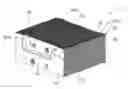
FIG. 4a is a perspective exploded view of a first embodiment of the thermal module of the present invention;
FIG. 4b is a perspective assembled view of the first embodiment of the thermal module of the present invention;
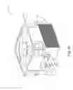
FIG. 4c is a right view of the first embodiment of the thermal module of the present invention;
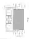
FIG. 5a is a perspective exploded view of a second embodiment of the thermal module of the present invention;
FIG. 5b is a perspective assembled view of the second embodiment of the thermal module of the present invention; and
FIG. 5c is a right view of the second embodiment of the thermal module of the present invention.
DETAILED DESCRIPTION OF THE PREFERRED EMBODIMENTS
Please refer to FIGS. 2a and 2b, in which FIG. 2a is a perspective view of a first embodiment of the heat sink wind guide structure of the present invention and FIG. 2b is a top view thereof. The heat sink wind guide structure includes a heat sink 3 having multiple radiating fins 31 and a wind incoming side 32. Each two adjacent radiating fins 31 define therebetween a heat dissipation flow way 33 in communication with the wind incoming side 32. The radiating fins 31 include a first radiating fin 311 and a second radiating fin 312, which are respectively positioned on two opposite outer sides of the heat sink 3. The first radiating fin 311 has a first extension end 3111 protruding from the first radiating fin 311. The second radiating fin 312 has a second extension end 3121 protruding from the second radiating fin 312.
In this embodiment, the heat sink 3 is composed of multiple radiating fins 31, which are piled up.
Please refer to FIGS. 3a and 3b, in which FIG. 3a is a perspective view of a second embodiment of the heat sink wind guide structure of the present invention and FIG. 3b is a top view thereof. The heat sink 3 of the second embodiment is identical to that of the first embodiment in structure and relationship between the respective components and thus will not be repeatedly described. The second embodiment is only different from the first embodiment in that the heat sink 3 of the second embodiment is an extruded aluminum heat sink 3.
Further referring to FIGS. 2a, 2b, 3a, 3b, a first wind guide wing 3112 and a second wind guide wing 3113 are respectively connected to two sides of the first extension end 3111. The first extension end 3111 and the first and second wind guide wings 3112, 3113 together define a first wind guide passageway 34. A third wind guide wing 3122 and a fourth wind guide wing 3123 are respectively connected to two sides of the second extension end 3121. The second extension end 3121 and the third and fourth wind guide wings 3122, 3123 together define a second wind guide passageway 35.
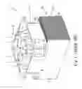
Please refer to FIGS. 4a, 4b and 4c, in which FIG. 4a is a perspective exploded view of a first embodiment of the thermal module of the present invention, FIG. 4b is a perspective assembled view of the first embodiment of the thermal module of the present invention and FIG. 4c is a right view thereof. In this embodiment, the thermal module 4 includes a heat sink 3, at least one heat pipe 5 and a fan 6.
The heat sink 3 has multiple radiating fins 31 and a wind incoming side 32. Each two adjacent radiating fins 31 define therebetween a heat dissipation flow way 33 in communication with the wind incoming side 32. The radiating fins 31 include a first radiating fin 311 and a second radiating fin 312, which are respectively positioned on two opposite outer sides of the heat sink 3. The first radiating fin 311 has a first extension end 3111 protruding from the first radiating fin 311. The second radiating fin 312 has a second extension end 3121 protruding from the second radiating fin 312.
The heat pipe 5 extends through the heat sink 3. The heat sink 3 has a heat absorption section 36 and a heat dissipation section 37. Two ends of the heat pipe 3 respectively pass through the heat absorption section 36 and heat dissipation section 37 of the heat sink 3.
The fan 6 is correspondingly mated with the wind incoming side 32 of the heat sink 3 to forcedly guide airflow 61 for dissipating heat from the heat sink 3.
In this embodiment, the heat sink 3 is composed of multiple radiating fins 31, which are piled up.
Please refer to FIGS. 5a, 5b and 5c, in which FIG. 5a is a perspective exploded view of a second embodiment of the thermal module of the present invention, FIG. 5b is a perspective assembled view of the second embodiment of the thermal module of the present invention and FIG. 5c is a right view thereof. The thermal module 4 of the second embodiment is identical to that of the first embodiment in structure and relationship between the respective components and thus will not be repeatedly described. The second embodiment is only different from the first embodiment in that the heat sink 3 of the second embodiment is an extruded aluminum heat sink 3.
Further referring to FIGS. 4a, 4b, 4c, 5a, 5b and 5c, a first wind guide wing 3112 and a second wind guide wing 3113 are respectively connected to two sides of the first extension end 3111. The first extension end 3111 and the first and second wind guide wings 3112, 3113 together define a first wind guide passageway 34 (as shown in FIG. 2b). A third wind guide wing 3122 and a fourth wind guide wing 3123 are respectively connected to two sides of the second extension end 3121. The second extension end 3121 and the third and fourth wind guide wings 3122, 3123 together define a second wind guide passageway 35 (as shown in FIG. 3b).
The fan 6 serves to forcedly guide the heat dissipation airflow 61 to dissipate heat from the heat sink 3 and the heat pipe 5. The heat dissipation airflow 61 goes from the wind incoming side 32 of the heat sink 3 into the heat sink 3. Then the heat dissipation airflow 61 goes through the heat dissipation flow ways 33 and is exhausted from the heat sink 3. The first and second extension ends 3111, 3112 on the opposite sides of the heat sink 3 serve to guide the heat dissipation airflow 61 toward two other sides of the heat sink 3. In this case, the heat generated by the heat-generating units 7 arranged around the heat sink 3 can be dissipated at the same time. Accordingly, the heat dissipation airflow 61 can be exhausted from many sides of the heat sink 3 to dissipate the heat of many heat-generating units 7 at the same time.
The above embodiments are only used to illustrate the present invention, not intended to limit the scope thereof. It is understood that many changes and modifications of the above embodiments can be made without departing from the spirit of the present invention. The scope of the present invention is limited only by the appended claims.
Claims
What is claimed is:1. A heat sink wind guide structure comprising a heat sink having multiple radiating fins and a wind incoming side, each two adjacent radiating fins defining therebetween a heat dissipation flow way in communication with the wind incoming side, the radiating fins including a first radiating fin and a second radiating fin, which are respectively positioned on two opposite outer sides of the heat sink, the first radiating fin having a first extension end protruding from the first radiating fin, the second radiating fin having a second extension end protruding from the second radiating fin.
2. The heat sink wind guide structure as claimed in claim 1, wherein a first wind guide wing and a second wind guide wing are respectively connected to two sides of the first extension end, the first extension end and the first and second wind guide wings together defining a first wind guide passageway, a third wind guide wing and a fourth wind guide wing being respectively connected to two sides of the second extension end, the second extension end and the third and fourth wind guide wings together defining a second wind guide passageway.
3. The heat sink wind guide structure as claimed in claim 1, wherein the heat sink is composed of multiple radiating fins, which are piled up.
4. The heat sink wind guide structure as claimed in claim 1, wherein the heat sink is an extruded aluminum heat sink.
5. A thermal module with heat sink wind guide structure, comprising:
a heat sink having multiple radiating fins and a wind incoming side, each two adjacent radiating fins defining therebetween a heat dissipation flow way in communication with the wind incoming side, the radiating fins including a first radiating fin and a second radiating fin, which are respectively positioned on two opposite outer sides of the heat sink, the first radiating fin having a first extension end protruding from the first radiating fin, the second radiating fin having a second extension end protruding from the second radiating fin; and
a fan mated with the wind incoming side of the heat sink.
6. The thermal module with heat sink wind guide structure as claimed in claim 5, wherein a first wind guide wing and a second wind guide wing are respectively connected to two sides of the first extension end, the first extension end and the first and second wind guide wings together defining a first wind guide passageway, a third wind guide wing and a fourth wind guide wing being respectively connected to two sides of the second extension end, the second extension end and the third and fourth wind guide wings together defining a second wind guide passageway.
7. The thermal module with heat sink wind guide structure as claimed in claim 5, wherein the heat sink is composed of multiple radiating fins, which are piled up.
8. The thermal module with heat sink wind guide structure as claimed in claim 5, wherein, the heat sink is an extruded aluminum heat sink.
9. The thermal module with heat sink wind guide structure as claimed in claim 5, wherein the heat sink has at least one heat pipe extending through the heat sink.
10. The thermal module with heat sink wind guide structure as claimed in claim 9, wherein the heat sink has a heat absorption section and a heat dissipation section, two ends of the heat pipe respectively passing through the heat absorption section and heat dissipation section of the heat sink.
Images & Drawings included:


Sources:
- United States Patent and Trademark Office - verify current appl. status at the USPTO↗
Recent applications in this class:
- » 20250271224 2025-08-28
HIGH POTENTIAL AND HIGH CORROSION RESISTANCE ALUMINUM ALLOY AND HIGH CORROSION RESISTANCE HEAT EXCHANGER - » 20250271223 2025-08-28
ALUMINUM ALLOY CORE MATERIAL FOR HEAT EXCHANGER, AND HEAT EXCHANGE TUBE AND HEAT EXCHANGER USING THE SAME - » 20250257958 2025-08-14
HEAT EXCHANGE TUBE FOR HEAT EXCHANGER, AND HEAT EXCHANGER - » 20250067526 2025-02-27
Heat exchanger based on gyroid/diamond hybrid minimal surface-based disturbance structure - » 20240337453 2024-10-10
HEAT EXCHANGER FOR A MOTOR VEHICLE WITH AN ALUMINUM ALLOY AND METHOD OF MANUFACTURE - » 20240271891 2024-08-15
TUBULAR BODY FOR A HEAT EXCHANGER, AND A MANUFACTURING PROCESS FOR THE SAME - » 20240191955 2024-06-13
HIGH CORROSION RESISTANCE HEAT EXCHANGER - » 20240125566 2024-04-18
HEAT TRANSFER MEMBER - » 20230243607 2023-08-03
Heat dissipation device assembly - » 20230050357 2023-02-16
HEAT EXCHANGER AND METHOD OF MANUFACTURING HEAT EXCHANGER
Recent applications for this Assignee:
- » 20120119498 2012-05-17
Wind power generation device for electronic equipment - » 20120039732 2012-02-16
Fan self-cooling structure with heat pipe - » 20110286183 2011-11-24
Water-cooled communication chassis - » 20110169379 2011-07-14
Heat insulation structure for cooling fan - » 20110120689 2011-05-26
Heat exchanger radiating fin structure and heat exchanger thereof - » 20110116943 2011-05-19
Stator structure, and motor and fan assembly using same - » 20110057080 2011-03-10
Structure for fixing a backplate - » 20110024100 2011-02-03
Heat radiating unit structure and heat sink thereof - » 20100315779 2010-12-16
Water-cooled communication chassis - » 20100307997 2010-12-09
Mounting rack structure and mounting hole adapter thereof