Re-Exchange Energy-Saving Building System
US20120042867A1
2012-02-23
12/858,722
2010-08-18
Abstract:
A re-exchange energy-saving building system in which building power supply system allows to supply water from top floor pond to the capillary generator set; the electric energy generated by capillary generator set is supplied to the user load, and the electric energy generated by solar PV is supplied to the water pump to transfer water from the basement pond to the top floor pond; the valley load in the utility power grid is supplied to the water pump to transfer water from the basement pond to the top floor pond. A parallel connection of solar water heaters, the hot water supply system for the building can provide hot water to the building at any time. The air conditioners for the building enable heating and cooling via GSHP. The water-saving system permits a membrane filter tank to filter the bath water and domestic water and then supply to the flush toilet at lower floor.
Interested in similar patents?
Get notified when new applications in this technology area are published.
Classification:
F24D5/005 » CPC main
Hot-air central heating systems ; Exhaust gas central heating systems combined with solar energy
F03B13/06 » CPC further
Adaptations of machines or engines for special use; Combinations of machines or engines with driving or driven apparatus ; Power stations or aggregates Stations or aggregates of water-storage type, e.g. comprising a turbine and a pump
F24D5/12 » CPC further
Hot-air central heating systems ; Exhaust gas central heating systems using heat pumps
F24D17/0021 » CPC further
Domestic hot-water supply systems using solar energy with accumulation of the heated water
F24D2200/11 » CPC further
Heat sources or energy sources Geothermal energy
F24D2200/12 » CPC further
Heat sources or energy sources Heat pump
F24D2200/14 » CPC further
Heat sources or energy sources Solar energy
F24D2220/08 » CPC further
Components of central heating installations excluding heat sources Storage tanks
F24S2020/17 » CPC further
Solar heat collectors specially adapted for particular uses or environments; Solar modules layout; Modular arrangements Arrangements of solar thermal modules combined with solar PV modules
Y02B10/20 » CPC further
Integration of renewable energy sources in buildings Solar thermal
Y02B10/20 » CPC further
Integration of renewable energy sources in buildings Solar thermal
Y02B10/40 » CPC further
Integration of renewable energy sources in buildings Geothermal heat-pumps
Y02B10/40 » CPC further
Integration of renewable energy sources in buildings Geothermal heat-pumps
Y02B10/50 » CPC further
Integration of renewable energy sources in buildings Hydropower in dwellings
Y02B10/50 » CPC further
Integration of renewable energy sources in buildings Hydropower in dwellings
Y02B10/70 » CPC further
Integration of renewable energy sources in buildings Hybrid systems, e.g. uninterruptible or back-up power supplies integrating renewable energies
Y02B10/70 » CPC further
Integration of renewable energy sources in buildings Hybrid systems, e.g. uninterruptible or back-up power supplies integrating renewable energies
Y02B30/13 » CPC further
Energy efficient heating, ventilation or air conditioning [HVAC] Hot air central heating systems using heat pumps
Y02B30/13 » CPC further
Energy efficient heating, ventilation or air conditioning [HVAC] Hot air central heating systems using heat pumps
Y02E10/20 » CPC further
Energy generation through renewable energy sources Hydro energy
Y02E10/20 » CPC further
Energy generation through renewable energy sources Hydro energy
Y02E60/16 » CPC further
Enabling technologies; Technologies with a potential or indirect contribution to GHG emissions mitigation Mechanical energy storage, e.g. flywheels or pressurised fluids
Y02E60/16 » CPC further
Enabling technologies; Technologies with a potential or indirect contribution to GHG emissions mitigation Mechanical energy storage, e.g. flywheels or pressurised fluids
Description
BACKGROUND OF INVENTION
1. Field of the Invention
The present invention relates generally to a building technology, and more particularly to an innovative one which involves power supply, hot water supply, air conditioning, water-saving and fire protection systems for the buildings.
2. Description of Related Art
The power supply system for the buildings is generally stemmed from utility power grid with higher cost.
The hot water supply system for the buildings is generally originated from solar water heater, whereby water is heated up electrically by various users. The disadvantages include: hot water over 90° C. must be heated up by the users with higher power consumption and water cost.
The flush toilet for the buildings adopts tap water with higher consumption of water resources.
The air conditioner for the buildings is used for electrical heating and cooling without auxiliary power supply, leading to higher energy consumption.
The fire protection system for the buildings is required to maintain regularly the pressure of fire water tank at top floor, meanwhile the fire pump has to be often activated in a complicated procedure.
Content of Invention
The primary objective of the present invention is to provide a re-exchange energy-saving building system, whereby the hot water supply system can supply hot water for the building, the air conditioner enables heating and cooling via a GSHP (ground source heat pump), the water-saving system permits a membrane filter tank to filter the bath water and domestic water and then supply to the flush toilet at lower floor. This saves the power and water consumption, and also reduces the cost of hot water and air conditioning; moreover, fire prevention water can be obtained from water tank on the top floor.
The technical solution of the present invention is described below: A re-exchange energy-saving building system covers a building and a building power supply system, which comprising: top floor pond, basement pond, capillary generator set, Solar PV, valley load, water pump and user load.
The top floor pond is arranged at the roof of the building, and the basement pond is arranged underground, of which water from top floor pond is supplied to the capillary generator set; the electric energy generated by the capillary generator set is supplied to the user load, and the electric energy generated by Solar PV energizes the water pump to transfer water from basement pond to top floor pond; the valley load in the utility power grid is supplied to the water pump to transfer water from basement pond to top floor pond and also to the user load.
The capillary generator set is composed of several small hydro generators, of which the inflow pipe is connected to the top floor pond, and the outflow pipe connected to the basement pond.
Said solar PV is arranged laterally onto the building, where the electric energy generated by solar PV is charged into the battery and then supplied to the water pump to transfer water from the basement pond to the top floor pond, whilst the valley load in the utility power grid is supplied to the water pump at nighttime to transfer water from the basement pond to the top floor pond.
Said hot water supply system for the building is composed of solar water heater, tap water, big hot water tank and hot water users; some solar water heaters are arranged on the upper part of the top floor pond, and a big hot water tank is arranged at top floor to supply hot water to the hot water users.
The solar water heaters are arranged in such a manner: tap water flows through level 1 parallel solar water heater, level 2 parallel solar water heater . . . level n parallel solar water heater's water tank into the big hot water tank; the number of individual solar water heaters in level 1 parallel solar water heater, level 2 parallel solar water heater . . . level n solar water heater increases one-by-one;
Parallel connection of solar water heaters means the water tanks of several solar water heaters are arranged in rows, there are only a single main water inlet and outlet, and the water tanks of solar water heaters in a row are connected.
The inlet pipeline of said level 1 parallel solar water heater is fitted with a flow control valve.
A drying box is arranged at the unit rooms in the building, a heating pipe is fixed in the drying box, and hot water in the big hot water tank is circularly connected to the heating pipe.
The water-saving system of the building is composed of the downcomer in the bathroom, sewage pipe, the downcomer for washing purposes, membrane filtration tank and flush toilet;
The flush toilet of unit rooms in the top floor is supplied from tap water, and the downcomer of this flush toilet is connected to the sewage pipe;
The downcomers of flush toilets in the unit rooms from 2nd floor are connected to the sewage pipe, the downcomers in the bathrooms and for washing purposes are connected to the water inlet of the membrane filtration tank; filtering membrane is fixed in the membrane filtration tank, and the outlet pipe of the membrane filtration tank is connected to the water inlet of flush toilet at lower floor; the outflow pipes of membrane filtration tanks in the unit rooms at the same floor are interconnected;
The downcomers of flush toilets in the unit rooms at the first floor, and the downcomers in the bathrooms or for washing purposes are connected to the sewage pipe.
Said air conditioner for the building is composed of underground heat exchange tube, GSHP unit, air conditioner users and big hot water tank;
The underground heat exchange tube is buried underground and connected to GSHP unit, which is then connected to air conditioner users, and the pipeline of big hot water tank is connected to the heat exchangers of air conditioner users.
Said fire protection system is composed of pipeline and hose nozzles, of which hose nozzles are arranged in the unit rooms and connected to the top floor pond.
The efficacies of the present invention lie in that:
-
- (1) The solar energy can be converted into hydropower for the capillary generator set, then the electric energy generated by the capillary generator set is supplied to the electric load of the building in a controlled way; the capillary generator set generates power where necessary, thus saving the potential energy of water resources. In the event of insufficient solar energy, valley load is used to pump water from the basement pond to the top floor pond; as the valley load's price is half of the electricity price in the daytime, this method could provide an electricity cost about 35% lower despite of the power loss during conversion of valley load's energy into the water potential energy and application by the capillary generator set. After the electric energy generated by the solar PV is charged into the battery, the energy is supplied to water pump for pumping water from the basement pond to the top floor pond; as the solar energy is not required to be extensively stored in the battery, this avoids higher storage cost, serious pollution and safety hazards when solar energy is extensively stored in the battery. In most cases, the electric energy generated from solar energy and water potential energy in the top floor pond are supplied to the power supply system of the building, saving greatly the power consumption cost by about 30%.
- (2) The water-saving system permits a membrane filter tank to filter the bath water and domestic water and then supply to the flush toilet at lower floor, thus saving greatly water resources.
- (3) The hot water supply system allows to arrange level 1 parallel solar water heater, level 2 parallel solar water heater . . . level n parallel solar water heater in sequence, then heat up the tap water for hot water supply. The tap water entering into the water storage tank of level 1 parallel solar water heater is kept constant, and the heat flux into the water storage tank of level 2 parallel solar water heater is increased gradually, so that tap water is heated up quickly to hot water; meanwhile, the flow is controlled to adjust the water temperature in the water storage tank of level n parallel solar water heater, making hot water available for the users in the building.
- (4) The air conditioner could provide heat sources by terrestrial heat and solar energy during winter, or refrigerate air source from ground source heat pump and supply to the rooms during summer, thus saving electric power and heating/cooling cost. In the winter, the hot water in the big hot water tank generated by solar water heater is added into the heat exchanger of air conditioners, helping to save electric power. In the cloudy or rainy weather, the recycling water in the air conditioner is heated up by GSHP unit, and pumped to heat exchanger in big hot water tank for the building.
- (5) The building cost of the present invention is 20˜30% higher than that of common buildings, but it only takes 2˜3 years to save the cost in terms of power/water consumption and air conditioning.
- (6) The water of top floor pond can be reserved for fire control; in the event of any fire hazard in the unit rooms, the water of top floor pond is available to guarantee timely and safe fire extinguishing. This eliminates the inconvenience of regular repair and maintenance of fire pump.
BRIEF DESCRIPTION OF THE DRAWINGS
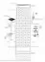
FIG. 1: a structural view of power supply system for the building
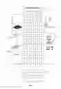
FIG. 2: a structural view of hot water supply system for the building
FIG. 3: a configuration view of solar energy heaters of the present invention
FIG. 4: a structural view of drying box
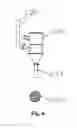
FIG. 5: a structural view of capillary generator set
FIG. 6: a structural view of small hydro generator in FIG. 4
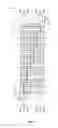
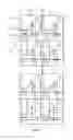
FIG. 7: a structural view of water-saving system for the building
FIG. 8: a structural view of water-saving system at uppermost two floors
FIG. 9: a structural view of water-saving system at lowermost two floors
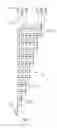
FIG. 10: a structural view of air conditioner for the building
DETAILED DESCRIPTION OF THE INVENTION
Preferred embodiment: referring to FIGS. 1˜10, a re-exchange energy-saving building system covers a building 1 and a power supply system 2 of the building 1, which comprising: top floor pond 21, basement pond 22, capillary generator set 23, solar PV 24, valley load 25, water pump 26 and user load 27;
The top floor pond 21 is arranged at the roof of the building 1, and the basement pond 22 is arranged underground, of which water from top floor pond 21 is supplied to the capillary generator set 23; the electric energy generated by the capillary generator set 23 is supplied to the user load 27, and the electric energy generated by solar PV 24 energizes the water pump 26 to transfer water from basement pond 22 to top floor pond 21; the valley load 25 in the utility power grid is supplied to the water pump 26 to transfer water from basement pond 22 to top floor pond 21 and also to the user load 27;
The capillary generator set 23 is composed of several small hydro generators 231, of which the inflow pipe 232 is connected to the top floor pond 21, and the outflow pipe 233 connected to the basement pond 22.
Said solar PV 24 is arranged laterally onto the building, where the electric energy generated by solar PV 24 is charged into the battery and then supplied to the water pump 26 to transfer water from the basement pond 22 to the top floor pond 21, whilst the valley load 25 in the utility power grid is supplied to the water pump 26 at nighttime to transfer water from the basement pond 22 to the top floor pond 21.
Said hot water supply system 3 for the building 1 is composed of solar water heater 31, tap water 32, big hot water tank 33 and hot water users 34; some solar water heaters 31 are arranged on the upper part of the top floor pond 21, and a big hot water tank 33 is arranged at top floor to supply hot water to the hot water users 34; the solar water heaters are arranged in such a manner: tap water 32 flows through level 1 parallel solar water heater 311, level 2 parallel solar water heater 312 . . . water tank of level n parallel solar water heater 31n into the big hot water tank 33; the number of individual solar water heaters in level 1 parallel solar water heater 311, level 2 parallel solar water heater 312 . . . level n solar water heater 31n increases one-by-one; parallel connection of solar water heaters means the water tanks of several solar water heaters 31 are arranged in rows, there are only a single main water inlet and outlet, and the water tanks of solar water heaters 31 in a row are connected.
The inlet pipeline of said level 1 parallel solar water heater 311 is fitted with a flow control valve 35.
Drying box 36 is arranged at the unit rooms in the building 1, heating pipe 361 is fixed in the drying box 36, and hot water in the big hot water tank 33 is circularly connected to the heating pipe 361.
The water-saving system 4 of the building 1 is composed of the downcomer 41 in the bathroom, sewage pipe 42, the downcomer 43 for washing purposes, membrane filtration tank 44 and flush toilet 45;
The flush toilet 45 of unit rooms in the top floor is supplied from tap water, and the downcomer of this flush toilet 45 is connected to the sewage pipe 42;
The downcomers of flush toilets 45 in the unit rooms from 2nd floor are connected to the sewage pipe 42, the downcomers 41, 43 in the bathrooms and for washing purposes are connected to the water inlet of the membrane filtration tank 44; filtering membrane is fixed in the membrane filtration tank 44, and the outlet pipe of the membrane filtration tank 44 is connected to the water inlet of flush toilet 45 at lower floor; the outflow pipes of membrane filtration tanks 44 in the unit rooms at the same floor are interconnected;
The downcomers of flush toilets 45 in the unit rooms at the first floor, and the downcomers 41, 43 in the bathrooms or for washing purposes are connected to the sewage pipe 42.
Said air conditioner 5 for the building is composed of underground heat exchange tube 51, GSHP unit 52, air conditioner users 53 and big hot water tank 33; the underground heat exchange tube 51 is buried underground and connected to GSHP unit 52, which is then connected to air conditioner users 53, and the pipeline of big hot water tank 33 is connected to the heat exchangers 531 of air conditioner users 53.
Said fire protection system for the building 1 is composed of pipeline and hose nozzles, of which hose nozzles are arranged in the unit rooms and connected to the top floor pond 1.
Claims
1. A re-exchange energy-saving building system covering the building, which is characterized by that: the power supply system for the building comprises: top floor pond, basement pond, capillary generator set, solar PV, valley load in the utility power grid, water pump and user load;
the top floor pond is arranged at the roof of the building, and the basement pond is arranged underground, of which water from top floor pond is supplied to the capillary generator set; the electric energy generated by the capillary generator set is supplied to the user load, and the electric energy generated by solar PV energizes the water pump to transfer water from basement pond to top floor pond; the valley load in the utility power grid is supplied to the water pump to transfer water from basement pond to top floor pond and also to the user load;
the capillary generator set is composed of several small hydro generators, of which the inflow pipe is connected to the top floor pond, and the outflow pipe connected to the basement pond.
2. The re-exchange energy-saving building system as claimed in claim 1, wherein it is characterized by that: said solar PV is arranged laterally onto the building, where the electric energy generated by solar PV is charged into the battery and then supplied to the water pump to transfer water from the basement pond to the top floor pond, whilst the valley load in the utility power grid is supplied to the water pump at nighttime to transfer water from the basement pond to the top floor pond.
3. The re-exchange energy-saving building system as claimed in claim 1, wherein it is characterized by that: said hot water supply system for the building is composed of solar water heater, tap water, big hot water tank and hot water users; some solar water heaters are arranged on the upper part of the top floor pond, and a big hot water tank is arranged at top floor to supply hot water to the hot water users; the solar water heaters are arranged in such a manner: tap water flows through level 1 parallel solar water heater, level 2 parallel solar water heater . . . level n parallel solar water heater's water tank into the big hot water tank; the number of individual solar water heaters in level 1 parallel solar water heater, level 2 parallel solar water heater . . . level n solar water heater increases one-by-one; parallel connection of solar water heaters means the water tanks of several solar water heaters are arranged in rows, there are only a single main water inlet and outlet, and the water tanks of solar water heaters in a row are connected.
4. The re-exchange energy-saving building system as claimed in claim 3, wherein it is characterized by that: the inlet pipeline of said level 1 parallel solar water heater is fitted with a flow control valve.
5. The re-exchange energy-saving building system as claimed in claim 3, wherein it is characterized by that: a drying box is arranged at the unit rooms in the building, a heating pipe is fixed in the drying box, and hot water in the big hot water tank is circularly connected to the heating pipe.
6. The re-exchange energy-saving building system as claimed in claim 1, wherein it is characterized by that: the water-saving system of the building is composed of the downcomer in the bathroom, sewage pipe, the downcomer for washing purposes, membrane filtration tank and flush toilet; the flush toilet of unit rooms in the top floor is supplied from tap water, and the downcomer of this flush toilet is connected to the sewage pipe; the downcomers of flush toilets in the unit rooms from 2nd floor are connected to the sewage pipe, the downcomers in the bathrooms and for washing purposes are connected to the water inlet of the membrane filtration tank; filtering membrane is fixed in the membrane filtration tank, and the outlet pipe of the membrane filtration tank is connected to the water inlet of flush toilet at lower floor; the outflow pipes of membrane filtration tanks in the unit rooms at the same floor are interconnected; the downcomers of flush toilets in the unit rooms at the first floor, and the downcomers in the bathrooms or for washing purposes are connected to the sewage pipe.
7. The re-exchange energy-saving building system as claimed in claim 1, wherein it is characterized by that: said air conditioner for the building is composed of underground heat exchange tube, GSHP unit, air conditioner users and big hot water tank; the underground heat exchange tube is buried underground and connected to GSHP unit, which is then connected to the heat exchangers of air conditioner users, and the pipeline of big hot water tank is also connected to the heat exchangers of air conditioner users.
8. The re-exchange energy-saving building system as claimed in claim 1, wherein it is characterized by that: said fire protection system is composed of pipeline and hose nozzles, of which hose nozzles are arranged in the unit rooms and connected to the top floor pond.
Images & Drawings included:


Sources:
- United States Patent and Trademark Office - verify current appl. status at the USPTO↗
Recent applications in this class:
- » 20250172297 2025-05-29
AIR SEPARATOR WITHIN A SOLAR AIR COLLECTOR - » 20250003603 2025-01-02
SYSTEM FOR ADJUSTING AND CONTROLLING TEMPERATURE OF INTELLIGENT NEW ENERGY FARMHOUSE INTEGRATED WITH TUNNEL WIND AND SOLAR ENERGY - » 20230417425 2023-12-28
Solar phase-change energy storage heating ventilation partition wall and modular heating system thereof - » 20230090226 2023-03-23
Systems and methods for direct use of solar energy - » 20210317996 2021-10-14
SOLAR SPACE HEATING COLLECTOR - » 20210302030 2021-09-30
COMMERCIAL BUILDING SOLAR HEATING SYSTEM - » 20200182486 2020-06-11
Solar thermal roofing system - » 20180209665 2018-07-26
Transpired Solar Collector - » 20170059184 2017-03-02
Solar thermal roofing system - » 20160273783 2016-09-22
Thermal insulating apparatus and uses thereof