Projection lens
US20120044584A1
2012-02-23
12/888,385
2010-09-22
✅ Patent granted
US 8,203,792 B2
2012-06-19
-
-
James Greece
2030-12-03
Abstract:
A projection lens comprises, from a long conjugate side to a short conjugate side, a first lens unit with positive optical power, a second lens unit with negative optical power, and a third lens unit with negative optical power. The first lens unit is configured for correcting chromatic aberration of the projection lens. The third lens unit comprises a meniscus lens which is convex toward to the short conjugate side of the projection lens.
Inventors:
- CHAO-YI YEH 5 🇹🇼 Chu-Nan, Taiwan
- JYH-LONG CHERN 20 🇹🇼 Chu-Nan, Taiwan
- Jyh-Long Chern 13 🇹🇼 Miao-Li Hsien, Taiwan
- Chao-Yi Yeh 3 🇹🇼 Miao-Li Hsien, Taiwan
Assignee:
- FOXSEMICON INTEGRATED TECHNOLOGY, INC. 312 🇹🇼 Chu-Nan, Taiwan
- FOXSEMICON INTEGRATED TECHNOLOGY, INC. 149 🇹🇼 Chu-Nan, Miao-Li Hsien, Taiwan
Interested in similar patents?
Get notified when new applications in this technology area are published.
Classification:
G02B3/00 IPC
Simple or compound lenses
G02B13/16 » CPC further
Optical objectives specially designed for the purposes specified below for use in conjunction with image converters or intensifiers, or for use with projectors, e.g. objectives for projection TV
G02B13/18 » CPC main
Optical objectives specially designed for the purposes specified below with lenses having one or more non-spherical faces, e.g. for reducing geometrical aberration
G02B9/12 IPC
Optical objectives characterised both by the number of the components and their arrangements according to their sign, i.e. + or - having three components only
Description
BACKGROUND
1. Technical Field
The present disclosure generally relates to lenses and particularly, to a projection lens for projection apparatus.
2. Description of Related Art
Lenses are usually employed in projectors, such as digital light processing (DLP) projectors, liquid crystal display (LCD) projectors, etc. In the design of above-mentioned projection systems, high resolution, low distortion, lateral chromatic aberration correction are always major concerns.
Therefore, what is needed is a projection lens capable of achieving high resolution, low distortion and lateral chromatic aberration correction.
BRIEF DESCRIPTION OF THE DRAWINGS
Many aspects of the disclosure can be better understood with reference to the following drawing. The components in the drawing are not necessarily drawn to scale, the emphasis instead being placed upon clearly illustrating the principles of the disclosure. Moreover, in the drawing, like reference numerals designate corresponding parts throughout the whole view.
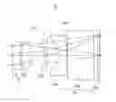
The only drawing is a schematic isometric view of a projection lens, according to an exemplary embodiment.
DETAILED DESCRIPTION
Reference will now be made to the drawing to describe the present projection lens, in detail.
Referring to FIG. 1, a projection lens 10 according to an exemplary embodiment is provided. The projection lens 10 includes, from a long conjugate side to a short conjugate side, a first lens unit 11 with positive optical power, a second lens unit 12 with negative optical power, and a third lens unit 13 with negative optical power.
The first lens unit 11 is configured for correcting chromatic aberration of the projection lens 10. The first lens unit 11 includes at least one lens with positive optical power. In present embodiment, the first lens unit 11 includes two lenses 110, 112. Each of the lenses 110, 112 can be a resin complex lens or a glass lens. In a still further embodiment, at least one lens of the first lens unit 11 has an aspherical lens surface.
The second lens unit 12 includes at least one lens with negative optical power. In present embodiment, the second lens unit 12 includes a solely lens 120. The lens 120 has a negative optical power and can be a resin complex lens or a glass lens.
The third lens unit 13 includes at least one meniscus lens 130. The meniscus lens 130 has a convex surface 1302 facing toward to the short conjugate side of the projection lens 10 (right side in FIG. 1). The meniscus lens 130 can be a resin complex lens or a glass lens. In present embodiment, the meniscus lens 130 has a negative optical power; the third lens unit 13 further includes two plate-like lenses 132, 134. The plate-like lens 132, 134 are actually light transmissive/transparent plates. Each of the plate-like lens 132, 134 can be a resin complex lens or a glass lens.
The projection lens 10 satisfies conditions:
0.1 < f 2 / f 3 < 0.4 ; ( 1 ) 0.6 < f 1 / f < 0.9 ; ( 2 ) 1.2 < BFL / h < 1.6 ; ( 3 ) 0.7 < f / BFL < 1.2 ; ( 4 )
wherein f represents a focal length of the projection lens 10, f1 represents a focal length of the first lens unit 11, f2 represents a focal length of the second lens unit 12, f3 represents a focal length of the third lens unit 13, BFL represents a back focal length of the projection lens 10, h represents an object height.
In a still further embodiment, the lenses 110, 112, 120 and 130 have an aspherical design which satisfies the following condition:
z = cvr 2 1 + 1 - cv 2 ( cc + 1 ) r 2 + ∑ A i r i ; ( 5 )
Wherein z represents an offset of the position point that has a height of “r”, cc represents a conic constant, r=√{square root over (x2+y2)} represents a height of the lens surface relative to an optical axis of the lens, cv represents curvature of lens surface, Ai (i=0, 1, 2, 3, 4, . . . ) represents aspherical coefficients.
In the present embodiment, the projection lens is compact and has a total track length smaller than 30 millimeters (mm)
Following tables show numerical data on the projection lens 10 and the aspherical surfaces of the lenses of each lens unit, in three exemplary embodiments, wherein F/# represents f number of the projection lens 10.
FIRST EMBODIMENT
F/#=1.8; f=11.376616, h=8.157,
| Refractive | ||||
| Curvature Radius | Thickness | Index | Abbe Number | |
| Surface No. | (mm) | (mm) | (Nd) | (Vd) |
| 1 | 14.234 | 2.342 | 1.632 | 23 |
| 2 | 47.797 | 0.562 | — | — |
| 3 | 13.648 | 3.286 | 1.515 | 57 |
| 4 | −9.491 | 4.247 | — | — |
| 5 | −6.099 | 0.85 | 1.632 | 23 |
| 6 | −9.028 | 3.517 | — | — |
| 7 | −8.006 | 2.66 | 1.49 | 55.3 |
| 8 | −10.386 | 0.312 | — | — |
| 9 | ∞ | 8.3 | 1.846663 | 23.82516 |
| 10 | ∞ | 1.118 | — | — |
| 11 | ∞ | 0.7 | 1.5168 | 64.16641 |
| 12 | ∞ | 0.57 | — | — |
| coefficient |
| Conic | |||||
| Surface No. | Constant | AS2 | AS4 | AS6 | AS8 |
| 1 | −1 | 2.4453E−03 | −6.3569E−04 | −1.5620E−05 | 3.6954E−07 |
| 2 | −1 | 4.4294E−02 | −5.7179E−04 | 3.0466E−06 | −4.8113E−07 |
| 3 | 4.9937E−01 | 8.1677E−03 | −3.3687E−04 | −8.4229E−06 | −2.2051E−07 |
| 4 | 4.3571E−01 | −1.7971E−03 | −3.8787E−04 | −6.8109E−06 | −2.8356E−07 |
| 5 | −7.9807E−01 | 2.9465E−02 | 6.5424E−05 | 8.6513E−06 | 1.1306E−07 |
| 6 | −1 | 2.6423E−02 | 3.0722E−04 | 4.3321E−06 | −1.5789E−07 |
| 7 | 9.7702E−01 | 5.1571E−03 | −2.5496E−04 | −1.6613E−05 | −4.0583E−07 |
| 8 | 8.6833E−01 | 4.3026E−02 | 2.5117E−05 | −4.7659E−06 | 2.5280E−08 |
| coefficient |
| Surface No. | AS10 | AS12 | AS14 | AS16 | AS18 |
| 1 | −8.7350E−08 | 1.1834E−08 | −4.4306E−11 | −9.3391E−11 | 4.4112E−12 |
| 2 | 4.6138E−08 | 1.2714E−10 | −1.1018E−10 | 3.8729E−12 | −9.2721E−14 |
| 3 | −1.0336E−08 | −4.8389E−10 | −2.3736E−11 | −1.8484E−12 | |
| 4 | −5.9867E−09 | −2.7710E−10 | −1.1169E−11 | −4.2299E−13 | −3.6578E−14 |
| 5 | −3.7593E−10 | 5.0030E−10 | 3.6302E−11 | 2.3510E−12 | 4.5496E−16 |
| 6 | 6.9475E−09 | 2.5442E−10 | 2.6659E−11 | 7.5296E−14 | 7.8365E−14 |
| 7 | −5.4313E−09 | −7.9895E−13 | 1.3844E−11 | 1.6121E−13 | −4.1741E−14 |
| 8 | 1.2623E−09 | 3.8849E−11 | −8.5770E−14 | −3.1292E−14 | 3.1825E−16 |
SECOND EMBODIMENT
F/#=1.8; f=11.522486; h=8.155;
| Refractive | ||||
| Curvature Radius | Thickness | Index | Abbe Number | |
| Surface No. | (mm) | (mm) | (Nd) | (Vd) |
| 1 | 14.441 | 2.372 | 1.632 | 23 |
| 2 | 47.994 | 0.554 | — | — |
| 3 | 13.358 | 3.441 | 1.515 | 57 |
| 4 | −9.498 | 4.091 | — | — |
| 5 | −6.124 | 0.943 | 1.632 | 23 |
| 6 | −8.919 | 3.402 | — | — |
| 7 | −8.197 | 2.833 | 1.49 | 55.3 |
| 8 | −10.451 | 0.376 | — | — |
| 9 | ∞ | 8.3 | 1.846663 | 23.82516 |
| 10 | ∞ | 1.154 | — | — |
| 11 | ∞ | 0.7 | 1.5168 | 64.16641 |
| 12 | ∞ | 0.47 | — | — |
| coefficient |
| Conic | |||||
| Surface No. | Constant | AS2 | AS4 | AS6 | AS8 |
| 1 | −1 | 2.1810E−03 | −6.7541E−04 | −1.7138E−05 | 3.8569E−07 |
| 2 | −1 | 4.3990E−02 | −6.1575E−04 | 1.3047E−06 | −5.0963E−07 |
| 3 | 4.9937E−01 | 1.0051E−02 | −2.5902E−04 | −8.7817E−06 | −3.4374E−07 |
| 4 | 4.3571E−01 | −6.6199E−04 | −4.1628E−04 | −6.2885E−06 | −3.0441E−07 |
| 5 | −7.9807E−01 | 2.8490E−02 | 1.7830E−04 | 1.4692E−05 | 2.4980E−07 |
| 6 | −1 | 2.6846E−02 | 3.0785E−04 | 5.1773E−06 | 1.3528E−08 |
| 7 | 9.7702E−01 | 7.6844E−03 | −3.5788E−04 | −1.8393E−05 | −4.3014E−07 |
| 8 | 8.6833E−01 | 4.7673E−02 | −3.2845E−05 | −6.1417E−06 | 2.0245E−08 |
| coefficient |
| Surface No. | AS10 | AS12 | AS14 | AS16 | AS18 |
| 1 | −8.3926E−08 | 1.2226E−08 | −9.5430E−12 | −9.3945E−11 | 4.0828E−12 |
| 2 | 4.3059E−08 | −2.1239E−10 | −1.3136E−10 | 3.0545E−12 | −1.0639E−13 |
| 3 | −1.4765E−08 | −6.6260E−10 | −4.1040E−11 | −3.4662E−12 | |
| 4 | −9.4946E−09 | −3.9722E−10 | −1.0875E−11 | −2.2473E−13 | −2.9585E−14 |
| 5 | 4.4685E−09 | 1.0664E−09 | 7.8203E−11 | 3.4712E−12 | −1.6497E−13 |
| 6 | 1.8707E−08 | 5.6305E−10 | 2.1470E−11 | −6.9443E−13 | 8.1342E−14 |
| 7 | −3.2339E−09 | 1.9523E−10 | 2.3229E−11 | 3.0763E−13 | −6.6451E−14 |
| 8 | 1.2799E−09 | 3.4219E−11 | −3.7052E−13 | −3.8851E−14 | 4.9396E−16 |
THIRD EMBODIMENT
F/#=1.8; f=11.376616; h=8.157;
| Refractive | ||||
| Curvature Radius | Thickness | Index | Abbe Number | |
| Surface No. | (mm) | (mm) | (Nd) | (Vd) |
| 1 | 14.452 | 2.416 | 1.632 | 23 |
| 2 | 46.697 | 0.555 | — | — |
| 3 | 13.395 | 3.493 | 1.53 | 56 |
| 4 | −9.534 | 4.040 | — | — |
| 5 | −6.107 | 0.944 | 1.632 | 23 |
| 6 | −8.965 | 3.351 | — | — |
| 7 | −8.479 | 2.921 | 1.515 | 57 |
| 8 | −10.300 | 0.377 | — | — |
| 9 | ∞ | 8.3 | 1.846663 | 23.82516 |
| 10 | ∞ | 1.137 | — | — |
| 11 | ∞ | 0.7 | 1.5168 | 64.16641 |
| 12 | ∞ | 0.486 | — | — |
| coefficient |
| Conic | |||||
| Surface No. | Constant | AS2 | AS4 | AS6 | AS8 |
| 1 | −1 | 2.2036E−03 | −6.8641E−04 | −1.7292E−05 | 3.8827E−07 |
| 2 | −1 | 4.4491E−02 | −6.2234E−04 | 6.2064E−07 | −5.0752E−07 |
| 3 | 4.9937E−01 | 9.9005E−03 | −2.5465E−04 | −9.2152E−06 | −3.9407E−07 |
| 4 | 4.3571E−01 | −2.3360E−04 | −4.3301E−04 | −6.1562E−06 | −2.9494E−07 |
| 5 | −7.9807E−01 | 2.8047E−02 | 1.7481E−04 | 1.6207E−05 | 3.2102E−07 |
| 6 | −1 | 2.7475E−02 | 3.7862E−04 | 6.5499E−06 | 6.8600E−08 |
| 7 | 9.7702E−01 | 9.7450E−03 | −3.8282E−04 | −1.9139E−05 | −4.3964E−07 |
| 8 | 8.6833E−01 | 4.9428E−02 | −1.2449E−04 | −6.6670E−06 | 2.3253E−08 |
| coefficient |
| Surface No. | AS10 | AS12 | AS14 | AS16 | AS18 |
| 1 | −8.3740E−08 | 1.2230E−08 | −8.4647E−12 | −9.3931E−11 | 4.0616E−12 |
| 2 | 4.3814E−08 | −2.1120E−10 | −1.3369E−10 | 2.8746E−12 | −1.1705E−13 |
| 3 | −1.5852E−08 | −6.3044E−10 | −3.8929E−11 | −3.5261E−12 | |
| 4 | −9.8891E−09 | −4.1658E−10 | −1.0270E−11 | −1.2057E−13 | −2.2671E−14 |
| 5 | 7.4375E−09 | 1.2802E−09 | 9.3139E−11 | 3.8238E−12 | −2.4977E−13 |
| 6 | 2.3354E−08 | 8.1545E−10 | 2.7662E−11 | −8.9252E−13 | 6.0568E−14 |
| 7 | −1.6495E−09 | 3.5663E−10 | 2.9897E−11 | 2.9922E−13 | −9.7967E−14 |
| 8 | 1.5821E−09 | 3.5602E−11 | −5.7088E−13 | −4.5204E−14 | 5.9727E−16 |
It is to be understood that the above-described embodiments are intended to illustrate rather than limit the disclosure. Variations may be made to the embodiments without departing from the spirit of the disclosure as claimed. The above-described embodiments illustrate the scope of the disclosure but do not restrict the scope of the disclosure.
Claims
What is claimed is:1. A projection lens comprising, from a long conjugate side to a short conjugate side, a first lens unit with positive optical power, a second lens unit with negative optical power, and a third lens unit with negative optical power, wherein
the first lens unit is configured for correcting chromatic aberration of the projection lens;
the third lens unit comprises a meniscus lens which is convex toward to the short conjugate side of the projection lens;
the projection lens satisfies conditions:
0.1 < f 2 / f 3 < 0.4 ; ( 1 ) 0.6 < f 1 / f < 0.9 ; ( 2 ) 1.2 < BFL / h < 1.6 ; ( 3 ) 0.7 < f / BFL < 1.2 ; ( 4 )
wherein f represents a focal length of the projection lens, f1 represents a focal length of the first lens unit, f2 represents a focal length of the second lens unit, f3 represents a focal length of the third lens unit, BFL represents a back focal length of the projection lens, h represents an object height.
2. The projection lens according to claim 1, wherein the first lens unit comprises two lenses, and at least one of the two lenses has a positive optical power.
3. The projection lens according to claim 2, wherein at least one lens of the first lens unit has an aspherical lens surface.
4. The projection lens according to claim 2, wherein the second lens unit comprises a lens with negative optical power.
5. The projection lens according to claim 4, wherein the third lens unit comprise a meniscus lens with negative optical power and convex toward to the short conjugate side of the projection lens.
6. The projection lens according to claim 5, wherein the lenses of the first lens unit, the second lens unit and the third lens unit satisfy condition:
z = cvr 2 1 + 1 - cv 2 ( cc + 1 ) r 2 + ∑ A i r i ; ( 5 )
wherein z represents an offset of the position point that has a height of “r”, cc represents a conic constant, r=√{square root over (x2+y2)} represents a height of the lens surface relative to an optical axis of the lens, cv represents curvature of lens surface, Ai (i=0, 1, 2, 3, 4, . . . ) represents aspherical coefficients.
7. The projection lens according to claim 1, wherein the projection lens has a total track length smaller than 30 millimeters.
Images & Drawings included:


Sources:
- United States Patent and Trademark Office - verify current appl. status at the USPTO↗
Similar patent applications:
- » 20190064676
Attenuation filter for projection lens, projection lens having attenuation filter for projection exposure apparatus, and projection exposure apparatus having projection lens - » 10396377
Projection lens, producing method of projection lens and projector having projection lens - » 20120275029
Projection lens, optical apparatus including projection lens, and method for manufacturing projection lens - » 20240045314
PROJECTION LENS, CONTROL METHOD OF PROJECTION LENS AND PROJECTION DEVICE - » 20210199854
Optical lens with antireflective film, projection lens, and projection lens optical system - » 20190265444
Wide-angle lens, projection lens, relay lens, projection-type display apparatus, and relay lens unit - » 20060285079
Projection lens, and projection display apparatus and rear projection display apparatus using the projection lens - » 20080278832
Projection lens unit and manufacturing method of projection lens unit - » 20080291552
Projection lens unit having reflection mirror in projection lens system and method of and equipment for fixing reflection mirror - » 20140307308
Reflective Optical Element for the EUV Wavelength Range, Method for Producing and for Correcting Such an Element, Projection Lens for Microlithography Comprising Such an Element, and Projection Exposure Apparatus for Microlithography Comprising Such a Projection Lens
Recent applications in this class:
- » 20250258361 2025-08-14
OPTICAL SYSTEM - » 20250231382 2025-07-17
OPTICAL SYSTEM AND IMAGE PICKUP APPARATUS - » 20250208385 2025-06-26
OPTICAL SYSTEM, VEHICLE-MOUNTED CAMERA AND VEHICLE - » 20250189769 2025-06-12
IMAGING OPTICAL SYSTEM - » 20250123471 2025-04-17
OPTICAL SYSTEM, OPTICAL MODULE, AND LIDAR DEVICE - » 20250085517 2025-03-13
OPTICAL LENS ASSEMBLY - » 20250044560 2025-02-06
OPTICAL SYSTEM AND CAMERA MODULE COMPRISING SAME - » 20250028156 2025-01-23
OPTICAL ELEMENT, FRONT OPTICAL UNIT OF AN OBJECTIVE, OBJECTIVE AND MICROSCOPE - » 20250004260 2025-01-02
NEAR-EYE DISPLAY DEVICE AND NEAR-EYE DISPLAY OPTICAL ASSEMBLY - » 20240361581 2024-10-31
OPTICAL SYSTEM AND IMAGING APPARATUS INCLUDING THE SAME
Recent applications for this Assignee:
- » 20140097767 2014-04-10
REMOTELY CONTROLLED SMART LIGHTING SYSTEM - » 20130300311 2013-11-14
LIGHT EMITTING DIODE LIGHTING DEVICE WITH DUTY CYCLE CAPABLE OF BEING TUNED - » 20130279168 2013-10-24
LIGHT-EMITTING DIODE LUMINOUS DEVICE - » 20130271988 2013-10-17
HEAT SINK AND LED LAMP USING THE SAME - » 20130265785 2013-10-10
LAMP SEAT ASSEMBLY - » 20130265773 2013-10-10
Modular lamp cover - » 20130265773 2013-10-10
Modular lamp cover - » 20130170183 2013-07-04
LED lamp - » 20130164556 2013-06-27
CIRCUIT BOARD WITH THERMALLY CONDUCTIVE LAYERS AND MANUFACTURING METHOD THEREFOR - » 20130163262 2013-06-27
LIGHT EMITTING DIODE (LED) LAMP ASSEMBLY