Heat dissipation device
US20120044649A1
2012-02-23
12/905,441
2010-10-15
✅ Patent granted
US 8,363,405 B2
2013-01-29
-
-
Boris Chervinsky
Altis Law Group, Inc.
2031-04-24
Abstract:
A heat dissipation device is used for heat dissipating for an electronic element. The heat dissipation device includes a heat sink and a buffer arranged between the heat sink and the electronic element. The buffer is made of elastic and thermally conductive material.
Assignee:
- HON HAI PRECISION INDUSTRY CO., LTD. 12,833 🇹🇼 Tu-Cheng, Taiwan
- HON HAI PRECISION INDUSTRY CO., LTD. 10,014 🇹🇼 New Taipei, Taiwan
Applicant:
Interested in similar patents?
Get notified when new applications in this technology area are published.
Classification:
H05K7/20 IPC
Constructional details common to different types of electric apparatus Modifications to facilitate cooling, ventilating, or heating
H05K7/20 IPC
Constructional details common to different types of electric apparatus Modifications to facilitate cooling, ventilating, or heating
H01L23/433 » CPC main
Details of semiconductor or other solid state devices; Arrangements for cooling, heating, ventilating or temperature compensation ; Temperature sensing arrangements; Fillings or auxiliary members in containers or encapsulations selected or arranged to facilitate heating or cooling Auxiliary members in containers characterised by their shape, e.g. pistons
H01L23/36 » CPC further
Details of semiconductor or other solid state devices; Arrangements for cooling, heating, ventilating or temperature compensation ; Temperature sensing arrangements Selection of materials, or shaping, to facilitate cooling or heating, e.g. heatsinks
H01L2924/0002 » CPC further
Indexing scheme for arrangements or methods for connecting or disconnecting semiconductor or solid-state bodies as covered by; Technical content checked by a classifier Not covered by any one of groups , and
H01L2924/00 » CPC further
Indexing scheme for arrangements or methods for connecting or disconnecting semiconductor or solid-state bodies as covered by
Description
BACKGROUND
1. Technical Field
The present disclosure relates to a heat dissipation device.
2. Description of Related Art
A heat dissipation device usually includes a heat sink directly attached to an electronic element. As a result, the electronic element may be damaged if the heat dissipation device suffers any impact once attached, such as often happens during assembly and transportation of a machine using the heat dissipation device.
BRIEF DESCRIPTION OF THE DRAWINGS
Many aspects of the present embodiments can be better understood with reference to the following drawings. The components in the drawings are not necessarily drawn to scale, the emphasis instead being placed upon clearly illustrating the principles of the present embodiments. Moreover, in the drawings, all the views are schematic, and like reference numerals designate corresponding parts throughout the several views.
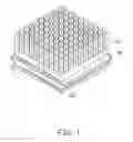
FIG. 1 is an assembled, isometric view of an embodiment of a heat dissipation device.
FIG. 2 is an exploded, isometric view of the heat dissipation device of FIG. 1.
FIG. 3 is a side view of the heat dissipation device of FIG. 1.
FIG. 4 is a side view of another embodiment of the heat dissipation device.
DETAILED DESCRIPTION
The disclosure, including the accompanying drawings, is illustrated by way of examples and not by way of limitation. It should be noted that references to “an” or “one” embodiment in this disclosure are not necessarily to the same embodiment, and such references mean at least one.
Referring to FIGS. 1 and 2, an exemplary embodiment of a heat dissipation device used for dissipating heat generated by an electronic element 102 mounted on a board 100. The electronic element 102 may be a central processing unit. The heat dissipation device includes a heat sink 20 and a buffer 30.
The heat sink 20 includes a base 21 and a number of fins 23 extending from the base 21.
The buffer 30 is made of elastic and thermally conductive material, such as copper and/or silver. The buffer 30 is substantially Z-shaped. Obviously, the buffer 30 may be M-shaped or other appropriate shape. The buffer 30 includes a first plate 31, a second plate 33 substantially parallel to the first plate 31, and a buffering portion 35 formed between the first and second plates 31 and 33. Two mounting portions 311 extend from the first plate 31 diagonally, for mounting the buffer 30 to the board 100. The first plate 31 is in tight contact with the electronic element 102.
Referring to FIG. 3, the second plate 33 of the buffer 30 is connected to the base 21 of the heat sink 20 opposite to the fins 23, by jointing or riveting for example.
Referring to FIG. 4, in another embodiment, the base 21 of the heat sink 20 defines a channel 211, the second plate 33 of the buffer 30 may insert in the channel 211 to connect the buffer 30 to the base 21 of the heat sink 20. Obviously, in other embodiments, the buffer 30 and the base 21 of the heat sink 20 may be integrated during manufacture.
The buffer 30 may reduce damage to the electronic element 102 due to excessive vibration or impact to the heat sink 20.
It is to be understood, however, that even though numerous characteristics and advantages of the embodiments have been set forth in the foregoing description, together with details of the structure and function of the embodiments, the disclosure is illustrative only, and changes may be made in detail, especially in matters of shape, size, and arrangement of parts within the principles of the present disclosure to the full extent indicated by the broad general meaning of the terms in which the appended claims are expressed.
Claims
What is claimed is:1. A heat dissipation device used for heat dissipating for an electronic element, the heat dissipation device comprising:
a heat sink comprising a base and a plurality of fins extending from the base; and
a buffer made of elastic and thermally conductive material, wherein the buffer comprises a first plate attached to the electronic element, a second plate connected to the base of the heat sink opposite to the plurality of fins, and a buffering portion connected between the first and second plates.
2. The heat dissipation device of claim 1, wherein the buffer is made of copper and/or silver.
3. The heat dissipation device of claim 1, wherein the buffer is substantially Z-shaped.
4. The heat dissipation device of claim 1, wherein two mounting portions extend from the first plate of the buffer, for mounting the buffer to a board on which the electronic element is attached.
5. The heat dissipation device of claim 1, wherein the second plate of the buffer is connected to the base of the heat sink by jointing or riveting.
6. The heat dissipation device of claim 1, wherein the base of the heat sink defines a channel, the second plate of the buffer is inserted in the channel to connect the buffer to the base of the heat sink.
Images & Drawings included:


Sources:
- United States Patent and Trademark Office - verify current appl. status at the USPTO↗
Similar patent applications:
- » 20190212793
Heat dissipation device, heat dissipation assembly, air pipe assembly, and table having heat dissipation device - » 20120147561
HEAT DISSIPATION DEVICE, HEAT DISSIPATION METHOD FOR COMMUNICATION DEVICE, AND COMMUNICATION DEVICE - » 20190186840
Basic structural body for constructing heat dissipation device and heat dissipation device - » 20230055030
BASIC STRUCTURAL BODY FOR CONSTRUCTING HEAT DISSIPATION DEVICE AND HEAT DISSIPATION DEVICE - » 20210315134
Heat dissipation device, heat dissipation method and terminal - » 20220412666
BASIC STRUCTURAL BODY FOR CONSTRUCTING HEAT DISSIPATION DEVICE AND HEAT DISSIPATION DEVICE - » 20230209776
HEAT DISSIPATION DEVICE AND HEAT DISSIPATION DEVICE ASSEMBLING METHOD - » 20160273753
Heat dissipating device having increased heat dissipating capacity, light source unit including same heat dissipating device and projector including same light source unit - » 20190285357
MIDDLE MEMBER OF HEAT DISSIPATION DEVICE AND THE HEAT DISSIPATION DEVICE - » 20080142193
METHOD OF MANUFACTURING A HEAT DISSIPATION DEVICE AND A HEAT DISSIPATION DEVICE OBTAINED THEREBY
Recent applications in this class:
- » 20250210455 2025-06-26
COPLANAR CONTROL FOR FILM-TYPE THERMAL INTERFACE - » 20250191998 2025-06-12
ENHANCED BASE DIE HEAT PATH USING THROUGH-SILICON VIAS - » 20250183120 2025-06-05
EMBEDDED LIQUID COOLING - » 20240282667 2024-08-22
Enhanced base die heat path using through-silicon vias - » 20240234246 2024-07-11
INTEGRATED CIRCUIT DIRECT COOLING SYSTEMS AND RELATED METHODS - » 20240222222 2024-07-04
Embedded liquid cooling - » 20240186218 2024-06-06
MOLDED POWER MODULES WITH FLUIDIC-CHANNEL COOLED SUBSTRATES - » 20240105550 2024-03-28
Water Cooling System for Semiconductor Package - » 20240014100 2024-01-11
Coplanar control for film-type thermal interface - » 20240006268 2024-01-04
PACKAGE STRUCTURE AND METHOD OF FABRICATING THE SAME
Recent applications for this Assignee:
- » 20250218287 2025-07-03
METHOD OF GENERATING AND PROMPTING TRAFFIC INFORMATION, AND ROADSIDE DEVICE THEREOF - » 20250178535 2025-06-05
METHOD FOR CONSTRUCTING 3D PANORAMIC VIEW MODEL, VEHICLE-MOUNTED DEVICE, AND STORAGE MEDIUM - » 20250074444 2025-03-06
METHOD FOR EARLY WARNING A BLIND AREA, ELECTRONIC DEVICE AND STORAGE MEDIUM - » 20240416754 2024-12-19
DISPLAY CONTROL DEVICE, DISPLAY EQUIPMENT, AND VEHICLE EMPLOYING DEVICE - » 20240411051 2024-12-12
Light-emitting device array and optical transceiver system having the same - » 20240324114 2024-09-26
DISPLAY CONTROL DEVICE AND VEHICLE EMPLOYING DEVICE - » 20240295957 2024-09-05
METHOD FOR CONTROLLING ELECTRONIC DEVICE, ELECTRONIC DEVICE AND COMPUTER STROAGE MEDIUM EMPLOYING METHOD - » 20240257357 2024-08-01
METHOD FOR DETECTING OBSTACLES, ELECTRONIC DEVICE, AND STORAGE MEDIUM - » 20240203133 2024-06-20
LANE LINE RECOGNITION METHOD, ELECTRONIC DEVICE AND STORAGE MEDIUM - » 20240194999 2024-06-13
Robot using limiting device for locking battery