Heat recovery and demand ventiliation system
US20120052791A1
2012-03-01
12/807,018
2010-08-26
Abstract:
A ventilation system for an air conditioning system includes dampers, a heat exchange unit, and a control unit. One damper controls the flow of ambient air into the system. The other damper controls the flow of relief/exhaust air that is cannibalized from return air from a room or space being cooled (or heated) by the air conditioning system. The ventilation system utilizes a control algorithm in the control unit to calculate, at stepped spaced apart increasing room ventilation rates, increasing CO2 concentrations in the air in the room that are below a maximum desired CO2 concentration in a room. The control algorithm permits a control unit in the ventilation system to open and close the dampers to maintain a CO2 concentration in the room that is below the desired CO2 concentration level.
Interested in similar patents?
Get notified when new applications in this technology area are published.
Classification:
F24F11/77 » CPC main
Control or safety arrangements; Control systems characterised by their outputs; Constructional details thereof for controlling the supply of treated air, e.g. its pressure for controlling air flow rate or air velocity by controlling the speed of ventilators
F24F11/30 » CPC further
Control or safety arrangements for purposes related to the operation of the system, e.g. for safety or monitoring
F24F2011/0006 » CPC further
Control or safety arrangements for ventilation using low temperature external supply air to assist cooling
F24F2110/50 » CPC further
Control inputs relating to air properties Air quality properties
F24F2110/70 » CPC further
Control inputs relating to air properties; Air quality properties; Concentration of specific substances or contaminants Carbon dioxide
Y02B30/70 » CPC further
Energy efficient heating, ventilation or air conditioning [HVAC] Efficient control or regulation technologies, e.g. for control of refrigerant flow, motor or heating
Y02B30/70 » CPC further
Energy efficient heating, ventilation or air conditioning [HVAC] Efficient control or regulation technologies, e.g. for control of refrigerant flow, motor or heating
F24F7/007 IPC
Ventilation with forced flow
Description
This invention relates to heating and air conditioning systems.
More particularly, the invention relates to a system to facilitate ventilation air heat recovery and volume management while maintaining a high indoor air quality for human occupants. This invention will substantially reduce the energy consumption of heating and air conditioning systems in commercial and institutional buildings with high occupant densities (greater than 20 people per 1,000 square feet of occupied space).
Commercial and institutional buildings have long been equipped with constant air volume ventilation systems which employ a means for outside air to enter and leave the building. Recent technology also employs ventilation air volume control utilizing CO2 sensors and operable dampers. Such systems are controlled using a single point CO2 level as the ventilation reference value and the objective is to prevent objectionable odors and vapors from accumulating in buildings.
It has for many years been desirable to provide, when possible, improvements to such ventilation air systems.
Therefore, it is a principal objective of this invention to provide an improved system to ventilate a building in the most cost effective, energy efficient manner, and meet the requirements of indoor air quality standards developed by recognized authorities in the industry, specifically, ASHRAE Standard 62.1-2010.
This and other further objects will be apparent to those skilled in the art from the following detailed description thereof, taken in conjunction with the drawings, in which:
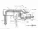
FIG. 1 illustrates a retrofit module constructed in accordance with one embodiment of the invention and installed in a pre-existing air conditioning or heating system;
FIG. 2 further illustrates the retrofit module of FIG. 1;
FIG. 3 illustrates an IRV graph prepared in accordance with the system of the invention;
FIG. 4 is a block flow diagram illustrating a heat transfer and ventilation control system constructed in accordance with the invention; and,
FIG. 5 is a block flow diagram illustrating a logic sequence utilized by a controller in the system of the invention illustrated in FIG. 4.
Briefly, in accordance with the invention provided are heat recovery and ventilation improvements in combination with a building structure. The building structure includes a room with a minimum occupancy density of 20 people per 1,000 square feet, an air conditioning system including a heat transfer coil, and a first section of duct D4 leading to the heat transfer coil of the air conditioning unit 22 to direct return air from the building structure over the coil. The building structure also includes a second section of duct D2 leading away from the heat transfer coil to carry conditioned (heated or cooled) supply air S1 from the coil back into the building. The ventilation improvements in the building structure comprise a retrofit heat recovery and ventilation control unit (DVHR) connected to the first section of duct D4. The DVHR unit includes a housing; a heat exchange unit 12; a section of duct D5 operatively associated with an outside ambient air source fan 13 to direct ambient air over the heat exchange unit 12 and into the first section of duct D1; an inlet damper 15 controlling the flow of ambient air into duct section D5 and over the heat exchange unit into the first section of duct D1; a section of duct D3 connected to the first section of duct to direct a portion R2 of the return air flowing through the first section of duct over the heat exchange unit and into the duct section D6 directing the air to the outside atmosphere via exhaust/relief fan 14; an outlet damper 16 controlling the flow of the portion of return/exhaust air R2 from the first section of duct D1 over the heat exchange unit and into the outside atmosphere; a control unit 30 operatively associated with the inlet and outlet dampers to control the rates of flow of ambient and exhaust/relief air, respectively, through the dampers; a first flow sensor 20B operatively associated with the inlet damper to generate signals to the control unit representing the rate of flow of ambient air through the inlet damper 15; a second flow sensor 21 operatively associated with the outlet damper 16; and a CO2 sensor in the room to generate signals to the control unit 30 representing the concentration of CO2 in the air in the room. The DVHR also includes a first fan 13 to direct ambient air into the section of duct D5, over the heat exchanger 12, and into the first section of duct D1; a second fan 14 to direct return/exhaust air R2 through the first section of duct D1, through the heat exchanger 12, and through duct section D6 and into the atmosphere. The ventilation control system also includes an algorithm in the control unit 30 to calculate, at stepped spaced apart increasing room ventilation rates corresponding to increases in room occupancy, acceptable CO2 concentrations below a maximum desired CO2 concentration in the room, and to increase or decrease the outside air ventilation rate to achieve the acceptable CO2 concentration.
In another embodiment of the invention, I provide improvements in combination with a building structure. The building structure includes a room with a maximum occupancy rating of at least twenty individuals per 1000 sq. ft. of occupied space, and an air conditioning system. The air conditioning system includes a heat transfer coil; a first section of duct (D4) leading to the heat transfer coil to direct return air from the building structure over the coil; and, a second section of duct (D2) leading away from the heat transfer coil to carry air from the coil back into the building, The improvements in the building structure comprise a retrofit ventilation control unit. The unit is attached to the first section of duct and includes a housing (23); a heat exchange unit (12); a third section of duct (D1) connected to the first section of duct (D4) to direct a first portion of return air from the room into the first section of duct; a fourth section of duct (D3) to direct a second portion of return air from the room over the heat exchange unit; a fifth section of duct (D5) to direct ambient air over the heat exchange unit into the third section of duct (D1). The heat exchange unit maintains the second portion of return air separate from the ambient air and transfers heat between the second portion of return air and the ambient air. The ventilation control unit also includes a sixth section of duct (D6) to direct the first portion of return air from the heat exchange unit into the outside atmosphere; an outlet damper (16) controlling the flow of the second portion of return air over the heat exchange unit (12) and into the outside atmosphere; an inlet damper (15) controlling the flow of the ambient air over the heat exchange unit (12); a control unit operatively associated with the inlet and outlet dampers to control the rate of flow of the ambient air and the second portion of the return air, respectively, through the dampers; a first flow sensor operatively associated with the inlet damper to generate signals to the control unit representing the rate of flow of ambient air through the inlet damper; a second flow sensor operatively associated with the outlet damper to generate signals to the control unit representing the rate of flow of the ambient air through the outlet damper; and, a CO2 sensor in the room to generate signals to the control unit representing the concentration of CO2 in the air in the room. The improvements also include a first fan to direct the ambient air into the fifth section of duct, over the heat exchanger, and into the first section of duct; a second fan to direct the second portion of return air from the fourth section of duct, and through the fourth section of duct over the heat exchanger, and into the atmosphere; and, an algorithm in the control unit to calculate, at stepped spaced apart increasing room ventilation rates, increasing CO2 concentrations in the air in the room that are below a maximum desired CO2 concentration in the room.
Turning now to the drawings, which depict the presently preferred embodiments of the invention for the purpose of illustrating the use thereof and not be way of limitation of the scope of the invention, and in which like reference characters refer to corresponding elements throughout the several views, in a preferred embodiment of the invention, the EMS (Energy Management System) serves primarily as a diagnostic tool to provide graphic user interface (GUI) capability for the entire campus HVAC and lighting systems. The GUI comprises a computer screen with graph interface software and includes (1) on screen representation of ambient air flow in cfm, (2) on screen representation of exhaust/relief air flow in cfm, (3) on screen representation of mode of operation i.e. (i) heat recovery heating mode (changeover function), (ii) heat recovery cooling mode (changeover function), and (iii) economizer cooling mode (changeover function), (4) on screen representation of occupied ‘active’ or ‘inactive’ mode, (5) on screen representation of which segment CO2 concentration limit is prevailing, (6) on screen representation of room CO2 concentration level, and (7) alarm functions associated with no air flow when dampers are expected to be in some open position or registering air flow, open damper position, when no air is to be moving. Room ventilation control functions and all algorithm defining characteristics, formulae and changeover functionality are embedded in the programmable controller hardware control board and processor. Ventilation control functions include (1) determining if the DVHR is to operate in the heat recovery mode or economizer mode based on outside air temperature (changeover functions), (2) calculating the IRV based on the algorithm, (3) varying the outside ambient air damper to maintain the proper CO2 concentration limit, and (4) varying the exhaust/relief air damper position to maintain the correct volume of air based on the outside/ambient air quantity. Changeover functions include (1) heat recovery heating mode (changeover function), (2) heat recovery cooling mode (changeover function), and (3) economizer cooling mode (changeover function). Input variables, i.e. room square footage, room ventilation rate (Va), people ventilation rate (Vp), (Occmax), are transmitted to the controller from external sources, i.e. plug-in interface tools, a keyboard or other data input means. It is the intent of this embodiment of the invention to maintain a maximum steady state ventilation to achieve less than the 700 ppm CO2 level exposure limit defined in ASHRAE 62-200. The maximum steady state ventilation rate is the calculated IRV based on the two independent ventilation rates of people and area. The steady state feature defines that the 700 ppm concentration increase in CO2 above ambient is accounted for in the algorithm in addition to the area ventilation requirement. Further, the energy recovery principles employed in this embodiment of the invention transfer a minimum of 60% of the differential dry bulb temperature energy from the high air stream temperature to the lower air stream temperature.
During the summer (cooling) months, the higher outside air temperature is transferred to the lower room relief air temperature. During the winter (heating) months, the higher room relief air temperature will transfer its heat to the lower outside air temperature. During periods of time when free cooling is available, the heat recovery (temperature transfer) unit is by-passed. Heat recovery in the cooling mode should be active at about 80° F. ambient temperatures and higher. Heat recovery in the heating mode should be active at about 50° F. ambient temperatures and lower. Economizer cooling should be the temperatures in between. These temperatures are usually ‘field’ adjustable so that when extreme conditions exist, the changeover temperatures can be reset without completely reprogramming the controller.
High occupant spaces historically experience transient and variable occupant loads. Prior to the 2010 version of ASHRAE 62.1-2010, indoor air quality (IAQ) standards defined constant use ventilation rates which influenced sizing of heating and cooling systems based on peak occupant loads. ASHRAE 62.1-2010 explains the intent of the ventilation standards with respect to volatile organic compound (VOC) dilution ventilation and CO2/physiological odor management. Two ventilation rates are independently derived to meet these separate IAQ comprising conditions and the sum of the two rates are intended to define the stead state rate CO2+VOC dilution rates to achieve a maximum CO2 exposure of 700 ppm above ambient.
The approach discussed below concerns the proper control of ventilation (ambient) air which is introduced into a room.
The Approach
ASHRAE 62.1-2010 requires a minimum cubic foot per minute (cfm) of outside air (Va) per square foot (sf) of occupied space (i.e., space in a room) for VOC dilution. Additionally, each person is assigned a ventilation value (Vp) in cfm per person for CO2/odor management which is based on occupant occupation or activity. All CO2 ventilation rates have been developed with the intent that a change of CO2 concentration in an occupied room will not be objectionable if the CO2 level is kept below 700 ppm above the outside ambient CO2 level. Since CO2 sensors measure the total CO2 in air, ambient CO2 levels (OSACO2) need to be measured. Ambient CO2 levels normally are in the range of 300 to 500 ppm. The maximum desired total CO2 concentration in a room in parts per million (ppm) is then equal to (OSACO2+700), or 1000 to 1200 ppm. When a ventilation system operates during periods when a room is occupied, and when a low occupant count is in the room, the CO2/odor management dilution rate can be met with the minimum VOC ventilation rate. The minimum ventilation rate equals (Va)(x), although this is a logical expression ASHRAE still requires separate dilution ventilation rates for CO2, even though it appears the VOC dilution rate can achieve both criteria.
If priority is placed on meeting the VOC ventilation requirements independently of the CO2 ventilation requirements, then upon start of any initial space ventilation sequence, the VOC dilution ventilation rate will define any minimum ventilation rate requirement. If the VOC dilution air quantity remains an independent ventilation air quantity (variable) in the total required steady state ventilation rate calculation, the resultant CO2 ppm concentration will always be substantially lower than the maximum allowable 700 ppm exposure limit, even at full occupancy of the room.
- 1. The control logic for the ventilation set forth in the approach discussed above requires an algorithm to define and respond to the rate of change in the occupancy of a room. A minimum unreduced VOC dilution ventilation air flow rate, (Va)(x) (where x=the sq. ft. area of a room), remains a constant to the controller when the room is occupied. ASHRAE 62.1-2010 defines a quantity of ambient ventilation air, Vp, per person to insure that the CO2 concentration in a room does not exceed a desired maximum concentration. Presuming that the Vp is calculated to insure that the CO2 concentration in a room does not exceed 700 ppm above the concentration, OSACO2, in the ambient air, then the outside air flow increases in response to an increase in occupant respiration (i.e., in response to an increase in the number of occupants in a room or a change in their activity level), and incremental target CO2 levels or checkpoints, RV, are defined to simultaneously achieve a constant VOC dilution ventilation rate and respond to increasing and decreasing occupancy of a room. The controller ventilation algorithm described below uses increases or decreases in room occupancy in incremental selected segments, where n is the number of segments selected, IRV is the size in cfm of each segment, and IRVpt is the estimated cumulative number of persons in a reset segment and any preceding reset segment. The number, and therefor the size, of each segment is adjusted as desired.
The design airflow of the VOC dilution ventilation (i.e., the base ventilation rate of Rb=(Va)(x)) plus the CO2 control ventilation (i.e., the size of each segment, IRV, times the number of segments S(1, 2, 3 . . . n)) is the divisor in the algorithm. The dampers 15, 16 (FIG. 1) which regulate the amount of outside air to the space have a defining minimum VOC dilution air flow, (Va)(x), as the initial open position. The occupied mode is determined by time schedule stored in the control unit 30 or by an occupant sensing mechanism operatively associated with the control unit 30. A velocity sensor utilizing a transducer records the inlet air flow quantity and adjusts the damper position to maintain a minimum set point. This is a pressure independent control function which is employed for air quantity and quality management functions of all air flow regulating devices in the system. When, as room occupancy increases, a maximum cfm of incoming ambient ventilation air, IRVcfm, is reached for a segment, the CO2 limit (i.e., the RV) for that segment is the upper CO2 limit for the prior segment. The minimum VOC ventilation rate=(Va)(x). This would suggest that the CO2/odor management rate is a duplicate of the minimum VOC ventilation rate. ASHRAE does not recognize this comparative analysis.
The control unit 30 achieves this upper CO2 by adjusting the damper that regulates the flow of incoming ambient air. In contrast, when the occupancy levels in a room decreases and the CO2 concentration in the room drops, the maximum cfm of a segment, IRVcfm, must be overshot by a selected amount before the target CO2 concentration is altered. For example, if in the system represented in FIG. 3, the room occupancy and CO2 concentration are decreasing, when the CO2 level reaches 668 ppm, coinciding with 228 cfm, the control unit 30 does not adjust the damper to achieve a CO2 concentration of 668 ppm (at 228 cfm) from 738 ppm (above 228 cfm) until the value drops to below the IRV cfm quantity of 228 by at least 10% of the difference of the segment air quantity, which in this case is 60 cfm×10%=6 cfm. This will allow the IRV to change once the outside air quantity reduces to less than 222 cfm. This percentage is a field adjustable value based on the normal occupancy of the space and how quickly it can gain or lose occupants. Its use is for this example.
When a building starts in the occupied ‘inactive’ mode, the ventilation rate is at its minimum. If no one enters the room, the room CO2 concentration will be essentially the ambient CO2 level. It is the intent of the control function to move to the first calculated segment RV upon occupant entry into the room. There is no way the ambient CO2 level of the room can be maintained once people enter. Therefore, the RV adjustment takes place once the air quantity exceeds its segment limit. Using FIG. 3, RV2@550 ppm will be the first occupied ‘active’ value. At 300 ppm (RV1), the ventilation rate is in the occupied ‘inactive’ mode.
The various necessary ventilation criteria set forth below are incorporated in the control unit 30 (FIG. 1). In one embodiment of the invention, ASHRAE 62.1-2010 VOC and CO2 management air flow rates are provided via a handheld plug-in. In another embodiment, this data is programmed into the control unit 30. When ASHRAE 62.1-2010 ventilation data is revised, a plug-in or any other desired data entry system is utilized to update the control unit 30.
Prior art ventilation systems typically have either fixed or on/off flow rates. Outside air introduced into a room or other space must be relieved from the space. When a space has no operable windows or doors which communicate with outside (ambient) air, the intake and relief systems permit equal volumes of air in and air out. Gravity air relief systems are most common. Exterior relief hoods or louvers are connected to a building or space via either a direct duct and grille in the ceiling, or a return/relief air grill in the ceiling which communicates with a return/relief air plenum.
During any ambient climate temperature condition, when the outside air can provide a lower temperature source to the air conditioning system than the set point of the temperature sensor without over cooling the space, the outside air supply source should not be tempered to a higher temperature in the heat exchange unit 12 (FIG. 1). This defeats the cooling process. Instead, in one embodiment of the invention, in the free cooling mode outside air is introduced to the return air path in the manner indicated by arrow A2 in FIG. 2, bypassing the heat exchange unit 12. This lowers the return air temperature to the air conditioning unit 22, thereby reducing the amount of compressorized cooling energy required to maintain the set point temperature in a room or other space. This is called the partial outside air economizer mode. Excess air generated by introducing air in a room or other space during the partial outside air economizer mode is relieved from the space via a gravity relief air system. The gravity relief air system has a back draft regulating damper to prevent outside air from entering into the building when the air conditioner if off. The back draft damper can be fitted with either a counterbalanced barometric relief damper or an electronically operated motorized damper. Either kind of damper will open when the air conditioner is operating during the partial outside air economizer mode.
When the ambient climate temperature conditions are not suitable for either free cooling or reduced compressorized cooling, the gravity relief air system is disabled and the heat exchange unit 12 is enabled. The heat exchange unit 12 works efficiently down to about 20% of the maximum air flow rate. In the system illustrated in FIG. 3, the maximum air flow rate is 408 cfm.
In the heat recovery mode of the module 10 (FIGS. 1 and 2) of the invention, as the ventilation air quality increases and decreases, dampers 15 and 16 are operated by the control unit 30. The control unit 30 ordinarily comprises a microprocessor. The control unit 30 utilizes the ventilation algorithm described below, along with any other desired algorithms. Ambient air that is introduced through damper 15 as ventilation air is compensated for by exhaust/relief air R2 (FIG. 1) that is directed over heat exchanger 12 and into the ambient atmosphere via damper 16. A minimum desired flow rate for ambient air through damper 15 is determined by the potential for trapping air borne particulates in the heat exchange unit 12 when the air velocity drops to below the manufacturer recommend air flow. Some manufacturers permit an air flow rate that is less than 20% of the maximum desired air flow rate over heat exchanger 12. In FIG. 3, the maximum desired air flow rate of ventilation air is 408 cfm.
Where occupied spaces communicate with the outside ambient air via operable windows and doors, a minor positive air pressure is maintained to minimize migration of air borne particulates into a room or other space. Such minor positive air pressures are not set forth in published standards, but up to 20% of the design maximum air flow rate (408 cfm in FIG. 3) can be diverted to the pressurization mode with minimal energy recovery impact at the design maximum desired air flow rate (i.e., air flow at peak occupancy). In FIG. 3, the maximum air flow rate is 408 cfm. It is recommended that no more than 10% of the maximum air flow rate (i.e., in the system of FIG. 3 this would be 40.8 cfm) be relieved for ventilation air flow up to 50% of the maximum air flow rate, and that the 20% maximum pressurization air flow quantity should not be exacted on the system until 80% of the design maximum desired air flow rate is in use.
The heat recovery operation mode requires verifiable air flow measurements for proper application of the ventilation algorithm. In order to maximize the reduction in energy required to operate the system, the flow rates of the incoming ambient ventilation air and of the exhaust/relief air stream should be the same or nearly the same. Toward this end, each air inlet (or outlet) is provided with a velocity sensor 20A, 20B, 21. It may be possible to use a common sensor for dampers 15 and 17 because these dampers will not open together. Each sensor is preferably calibrated and can operate to within 2% accuracy at velocity pressures as low as 250 fpm (0.03″ velocity pressure) at sea level.
During low occupant loads in a room or other building space, only a minimal amount of exhaust air, R2, may be available for heat recovery. During such periods of low ventilation air flow, however, the outside air cooling load on the room air conditioning system is also low, resulting in a minor increase to the cooling load of the air conditioning equipment above minimum (no outside cooling load). Algorithm calculated indoor air quality (IAQ) conditions are continuously maintained regardless of the quantity of exhaust air, R2, utilized.
The combination of heat recovery and demand ventilation control enables a substantial reduction in energy use, enables increased sustained IAQ, and enables enhancements in sustainable system performance. Enhancements include:
-
- a. Reduction of AC unit sizes based on the reduction of the cooling load
- b. Reduction of electrical service size based on smaller electrical loads of the smaller AC units
- c. Energy reduction of HVAC system energy use of 25%-40%
- d. Improvements of indoor air quality (IAQ)]
- i. Stable CO2 levels
- ii. Adequate VOC dilution
- iii. Reduction of space temperature variations
- iv. Noise reduction
- e. Reduction of the carbon footprint with the reduction of required utility generation
- f. Air conditioning system benefits
- i. Reduction of entering air temperatures to the evaporator and the resultant high differential pressures at the compressor
- ii. LEED compliance for all refrigerant systems if the normal size refrigerant charge is compared with the reduced unit size charge
- iii. Minimizing excess outside air into the building when occupancy is not at maximum
- iv. Partial outside air economizer use (not available with conventional heat recovery modules)
- v. Operable in all ambient temperatures from −10° F. to 120° F.
- g. Hydrocarbon power generator emitted pollution reduction at generating plants
- h. Water use reduction for cooling of utility generator equipment
- i. Reduction of global warming
- j. Refrigerant volume leakage reduction in package air conditioning equipment
- k. Reduction of water chemical treatment at industrial cooling towers of utility generating plants
- l. Reduction of ozone depleting and global warming refrigerant leakage.
Use of an occupant sensor(s) to manage IAQ and energy consumption is complimentary to a lighting control system. A lighting control system is an energy management tool required by the International Energy Conservation Code as an alternative to time clocks which use space occupant overrides for the light control system. One presently preferred occupant sensor utilizes infrared temperature sensor technology to determine the number of occupants in a room. Any human entry in to the sensor zone is detected and turns on light fixtures. EMS systems can control space lighting and HVAC during present hours of operation. Substantial energy and cost savings are realized if the sensor determine the presence of occupants and turn energy consuming systems on or off. Such an occupancy sensor can be furnished with an auxiliary contact to enable independent functioning of the lighting system from the HVAC system. The auxiliary contact determines if a ventilation adjustment is in order. The occupancy sensor also enables the “occupied” mode temperature sensor set point to be changed in response to an “active” status versus an “inactive” status. If, for example, during a scheduled “occupied” mode of the HVAC unit, the room sensor detects no human presence for a selected time period of five minutes, the HVAC unit serving the room can change to “occupied-inactive” status. This changes the room people and ventilation set points to zero outside air. When the room sensor detects human presence, the operating sequence for the DVHR (Demand Ventilation Heat Recovery) unit 10 of the invention begins. The first stage of the ventilation air management mode is utilized when a room is not occupied and is based on the outside ambient air temperature and includes the base ventilation rate, Rb=(Va)(x). Since the room is not occupied, (Vp)(Occact)=0. An outside air source temperature sensor determines if unit 10 operates in the Cooling-Heat Recovery (CHR) mode, the Heating-Heat Recovery (HHR) mode, or the Economizer-No Heat Recovery (EHNR) mode. When unit 10 operates either of the CHR or HHR modes, the occupancy sensor enables the “occupied-active” mode of the HVAC system. The ventilation ambient air damper 15 and the exhaust air damper 16 (FIG. 1) are opened, closed, or not adjusted in order to direct into the room the minimum necessary quantities of ventilation air as calculated by the ventilation algorithm. The velocity sensors 20A, 20B, 21, the indoor and outdoor temperature sensors, and the CO2 sensor in the room provide inputs to the EMS (Energy Management System). The indoor air quality (IAQ) and indoor and outdoor temperature sensors enable the cooling and heating systems to operate and the ventilation system algorithm determines calculates the RV set point of the room.
When operating in the ENHR mode, the bypass damper 17 (FIG. 2) is opened to its design maximum air flow as sensed by the velocity sensor 20A. The maximum outside air volume is calculated by the engineer using the peak air flow of the supply fan 13 divided by the number of DVHR units on its system. During the ENHR mode, the heat recovery module air pressure drop is excluded from the system losses because it is bypassed. This allows for the supply fan 13 to ramp up to a higher air flow because it doesn't have as much system resistance to overcome. This is a higher air quantity than the maximum fan capability if the sum of the total ventilation air flow required for proper IAQ is tabulated. This is a scheduled value on the drawings usually defined by the engineer.
The exhaust/relief damper 16 and the heat exchanger damper 15 are closed. Air is relieved from the room via a gravity relief system. When the ambient air quantity produces a temperature which is too cold and the room temperature drops to below the desired set point, the quantity of ventilation air is controlled based on readings produced by the room CO2 sensor until the IAQ set point can not be met and the temperature set point continues to drop. When this occurs, the HHR mode is enabled. In most cases, the morning warm-up condition shall enable the HHR mode. After the system begins operating in the HHR mode, the ENHR mode is enabled once the outside air temperature reaches 60 degrees F. or reaches another selected temperature. If at any time the ambient air temperature exceeds the set point of the room by five degrees F., the CHR mode is enabled.
An infrared sensor in the room or other space determines when the room is occupied. When the room is not occupied, the ventilation system of the invention is in an ‘inactive’ mode. When the room is occupied, the sensor generates and transmits signals to control unit 30. Control unit 30 places the ventilation system in the active mode, which triggers use of EQ. 1 (and consequently a graph comparable to that of FIG. 3) as set forth below.
Control unit 30 communicates with fans 13 and 14 to turn the fans on and off and to adjust the speed of operation of the fans.
The ventilation unit 10 illustrated in FIGS. 1 and 2 includes a housing 23, heat exchange unit 12 mounted in housing 23, damper(s) 15, 16, and 17 mounted in housing 23, velocity sensors 20A, 20B, and 21 mounted in housing 23, and a controller 30 mounted in the housing 23. Fans 13 and 14 can be mounted on housing 23, or can be mounted at locations separate from housing 23 to direct air through ducts that are connected to housing 23.
Duct D5 guides incoming ambient ventilation air A1 over one side of heat exchange unit 12, out into the duct of D1, and through duct D4 interconnecting unit 10 and air conditioning unit 22 (FIG. 2). Duct D3 guides a portion R2 of the return air over the other side of heat exchange unit 12 and out into the ambient air as exhaust/relief air. The return air comes from the room being ventilated by unit 10. Dampers 15 and 17 are mounted in duct D5. Damper 16 is mounted in duct D6.
Velocity sensors 20A, 20B, 21 are shown mounted in ducts D5 and D6, but that need not be the case. Sensors can be mounted at any desired location in ventilation unit 10 to obtain an accurate reading of ventilation air A1 entering duct D5 and of return air R2 exiting duct D6 as exhaust/relief air.
Velocity sensors 20A, 20B, 21 are operatively associated with control unit 30 and generate and transmit signals to control unit 30 defining the velocity of ambient air, indicated by arrow A1, traveling through ducts D5 and D1 into duct D4, and of return air, indicated by arrow R2, traveling through ducts D1 and D6.
Control unit 30 also receives signals from a CO2 sensor (not shown) in the room or other space being cooled (or heated) by the air conditioning unit 22. Control unit 30 can also, if desired, receive signals from a sensor that detects ambient temperature, from a sensor that detects the temperature in the room being cooled (or heated) by unit 22, from an infrared or other sensor that detects when one or more individuals are in the room, and from a sensor that indicates the desired temperature set point in the room.
While the shape and dimension of ventilation unit 10 can vary as desired, and unit 10 can be installed at any desired location near to or spaced apart from air conditioning unit 22, the embodiment of the invention illustrated in FIGS. 1 and 2 is a preferred embodiment because it is constructed to be inserted after a portion of ducting that leads to and carries return air to a previously installed air conditioning unit 22 is removed. After the portion of the return air ducting leading to the air conditioning unit 22 is removed, unit 10 is installed in-line to replace the portion of the return air ducting that was removed. Accordingly, return air R1 and R2 from the room flows into unit 10, portion R1 flows into ducts D3, D1 and D4 and into air conditioner 22, and portion R2 flows over or through heat exchanger 12 and out through duct D6. This, as can be seen in FIG. 2, eliminates or minimizes the amount of duct which must be utilized to install unit 10 in-line along a return air duct that is connected to air conditioner 22. In FIGS. 1 and 2, it is assumed that unit 10 is located outdoors. Unit 10 can also, if desired, be installed in a duct which is located indoors, or can be installed at any other desired location. And, as would be appreciated by those of skill in the art, unit 10 can be utilized and installed when a new air conditioner is being installed on or adjacent a building structure, or can be installed as an integral part of air conditioning unit during the manufacture of a new or refurbished air conditioning unit. Unit 10 is preferably, but not necessarily, manufactured as a self-contained module with a control unit 30 designed to receive necessary inputs from air velocity sensors 20A, 20B, 21, from a room CO2 sensor, from a room infrared occupancy sensor, from an ambient air temperature sensor, or from any other desired sensor that is part of self-contained unit or that is remote from unit 10. Fans 13 and 14 can be incorporated as a part of unit 10, or can be omitted from unit 10 and installed in or adjacent ducting that leads to unit 10. Similarly, dampers 15 to 17 can, as illustrated in FIGS. 1 and 2, be incorporated as part of unit 10, or can be omitted from unit 10 and installed in ducting leading to unit 10, as can control unit 30, velocity sensors 20A, 20B, 21, and heat exchange unit 12. The compact module configuration, with or without fans 13 and 14, illustrated in FIGS. 1 and 2 is presently much preferred in the practice of the invention.
As is illustrated in FIG. 1, a portion, R2, of the return air from the room is directed by fan 14 from duct D1 over one side of heat exchange unit 12 and into the ambient air as exhaust/relief air. The size, in cfm, of portion R2 is controlled by damper 16. Another portion R1 of the return air from the room continues through ducts D1 and D4 to air conditioning unit 22, where it travels over the cooling (or heating) coils and becomes part of the supply air, indicated by arrow S1, traveling through duct D2 to the room.
As is also illustrated in FIG. 1, ambient air, indicated by arrow A1, is directed by fan 13 over the other side of heat exchange unit 12 and into duct D1. This ambient air travels over the cooling (or heating) coils in air conditioning unit 22 and becomes part of the supply air, indicated by arrow S2, to the room.
When the ambient air is warmer than the desired temperature of the room, heat exchange unit 12 functions to transmit heat from the ambient air A1 to return air R2. When the ambient air A1 is cooler than the desired temperature of the room, heat exchange unit 12 functions to transmit heat from the return air R2 to the ambient air, A1.
In FIG. 2, damper 15 is closed. Ambient air A2 entering duct D5 travels through damper 17, through ducts D1 and D4, and into air conditioning unit 22. The operational configuration of FIG. 2 is utilized when the ambient air temperature is sufficiently cool to provide desired cooling to return air R1.
In FIGS. 1 and 2, D1 is an air duct integrated with D3 for return air to air conditioner 22; D2 is an air duct directing cooled (or heated) supply air S1 from air conditioner 22 back to the room; D3 is a duct through which return air from the room flows in unit 10; D4 is a duct that directs return air into the coil/fan section of air conditioner 22; D5 is a duct that directs ambient air A1 into unit 10 and over one side of heat exchange unit 12; D6 is a duct that directs exhaust/relief air from heat exchanger 12 into the ambient atmosphere; A1 and A2 are ambient air streams flowing into duct D5; A1 is a fan induced ambient air stream directed through or over heat exchange unit 12; A2 is a fan induced ambient air stream that bypasses heat exchange unit 12 and travels directing in the return air stream in the manner illustrated in FIG. 2; R2 is a portion of the return air stream that is drawn over or through heat exchange unit 12; and S1 is a combination of return air R1 and outside ambient air A1. FIG. 1 illustrates the heat recovery mode of the ventilation system of the invention. FIG. 2 illustrates the economizer mode of the invention. In the economizer mode, the temperature of the ambient air stream A2 permits it to be added directly to the return air stream R1 and obviates the necessity of passing an ambient air stream A1 over or through heat exchanger 12.
A control system ventilation formula is used to calculate the CO2 ppm target concentration levels that are required to maintain in a room a maximum 700 ppm CO2 exposure level for occupants as defined in ASHRAE 62.1-2010 (and earlier versions). This maximum 700 ppm CO2 exposure is in addition to the existing CO2 concentration in the ambient air.
There are two additive variables required to meet the ASHRAE standards:
a. One variable is the base “area ventilation rate”, i.e., the ventilation rate required for a room.
b. The other variable is the “person” ventilation rate, i.e., the ventilation rate to compensate for each person in a room.
The calculation used below approaches each of the additive variables to achieve a critical steady state result based on maintaining a maximum CO2 concentration of 700 ppm above the CO2 concentration in the ambient air.
Variables Used in Conjunction with the Control System Ventilation Formula
- x=square footage of the room
- Vp=area (i.e., room) ventilation rate requirement in cubic feet per minute (cfm/sq. ft), as listed in ASHRAE 62.1-2010, Table 6.1.
- Occmax=maximum code or user defined number of occupants in room
- Va=“per person” ventilation rate requirement in cfm/person, as listed in ASHRAE 62.1-2010 Table 6.1.
- CRT=rate reset variable based on outside air temperature during the cooling mode. This is used in relation to Va.
- CRT=1.0 for ambient less than or equal to 95 F
- CRT=0.8 for ambient less than or equal to 96 F and greater than 95.
- CRT=0.6 for ambient temperature less than or equal to 97 F and greater than 96 F.
- CRT=0.4 for ambient temperature less than or equal to 98 F and greater than 97 F.
- CRT=0.2 for ambient temperature less than or equal to 99 F and greater than 98 F.
- CRT=0.0 for ambient temperature greater than 99 F.
- In other words, if the ambient temperature is greater than 99 F, ambient air is not utilized to meet the area ventilation rate requirement, but is still used to meet the “per person” ventilation requirement.
- The CRT values are adjustable with a plug-in to take into account sensible cooling excesses associated with extremely high ambient conditions. Similar adjustments can be defined for very humid locations and will be based on a relative humidity—dry bulb temperature measurement which equals a wet-bulb temperature on the psychometric chart.
- HRT=rate reset variable based on outside air temperature during the heating mode. This is used in relation to Va.
- HRT=1.0 for ambient temperature greater than 25 F.
- HRT=0.8 for ambient less than or equal to 25 F and greater than 24.
- HRT=0.6 for ambient temperature less than or equal to 24 F and greater than 23 F.
- HRT=0.4 for ambient temperature less than or equal to 23 F and greater than 22 F.
- HRT=0.2 for ambient temperature less than or equal to 22 F and greater than 21 F.
- HRT=0.0 for ambient temperature less than or equal to 21 F.
- HRT values are adjustable using a plug-in to take into account sensible heating excesses associated with extremely low ambient conditions.
- OSACO2=concentration of CO2 in ambient air in ppm.
- Occact=count of number of people in room, usually determined by a CO2 concentration that is in excess of the CO2 concentration in the ambient air.
- IRV graph=a plot of selected spaced apart reset values (RVs). The units of measure on the vertical axis of the graph are ppm (parts per million) CO2. The units of measure on the horizontal axis of the graph are cfm (cubic feet per minute) ventilation air.
- Rb=base ventilation rate for a room in cfm=(Va)(x).
- n=the number of cfm reset segments selected for and represented on size to other segments, although this is not necessarily the case. IRV is the size of each segment in cfm.
- IRVpt=the cumulative number of calculated persons in a reset segment and any preceding reset segments.
- IRVcfm=a selected cfm point on the horizontal axis of an IRV graph at which a reset segment ends, at which an associated reset value (RV) occurs, and which represents a cumulative quantity (in cfm) of outside (ventilation) air that is utilized. The value of such a cfm point is equal to:
(Vp)(IRVpt)+(Va)(x)
- IRV=the size in cfm of each segment in an IRL graph. IRV equals the maximum outside air quantity (Vp×Occmax) divided by the number of reset segments (n) selected. If, for example, five reset segments are selected, the reset values (RV), or check points, occur at 0%, 20%, 40%, 60%, 80%, and 100% of the maximum (Vp×Occmax) outside air ventilation (in cfm) that will be utilized to offset the concentration of CO2 in the room that is above the concentration of CO2 in the ambient air. Each segment extends from one RV to an adjacent RV. For example, one segment extends from the cfm associated with the RV at 0% to the cfm associated with the RV at 20%. If ten reset segments are selected, the reset values occur at 0%, 10%, 20%, 30%, 40%, etc. of the maximum flow of ambient air that will be utilized to ventilate the room to offset CO2 concentrations above the CO2 concentration in the ambient air.
- RV=RVd+OSACO2=a reset value on an IRV graph. The number of RVs presently is one greater than the number, n, of segments. Each set value (RV) represents a desired CO2 concentration which is noted on the vertical axis of the graph and which is associated with a selected cfm point (IRVcfm) on the horizontal axis of the graph. The value of the selected cfm point (IRVcfm) indirectly indicates the “actual” number of people (Occact) in the room, i.e., the value of the selected cfm points less the base cfm of (Va)(x) is divided by Vp to give the “actual” number of people in the room. A reset value (RV) defines a desired total room CO2 concentration limit at its associated IRVcfm. A velocity sensor 20A, 20B in the incoming supply stream of ambient air indicates the cfm of the incoming air stream. As reset value (RV) is used to reset the CO2 maximum allowable ppm value for its associated IRVcfm. The control system of the invention sends a signal to the outside or ambient air stream damper motors which modulate the damper blades to adjust the outside air quantity in response to the CO2 concentration detected by CO2 sensor(s) and in response to how much the room CO2 deviates from the CO2 concentration defined by the RV.
- RVd=the difference, in ppm, at a selected cfm point on an IRV graph (IRVcfm) between the RV at that cfm and the ambient air CO2 concentration (OSACO2). Also known as CO2max.
- S(0, 1, 2, 3, . . . n)=a numerical value (0, 1, 2, 3 . . . n) representing the number of segments used in calculating, with the formula noted below, both an RV and the amount by which the RV exceeds the ambient CO2 concentration. For example, when the first set point RV1 is calculated, a numerical value of 0 is used for S; when the second set point RV2 is calculated, a numerical value of 1 is used for S; when the third set point RV3 is calculated, a numerical value of 2 is utilized, and so on. When S=0, a segment is not utilized and the RV=OSACO2.
- Altcorr=an altitude correction value. This value increases the IRV values above those established for sea level and extends the applicable segment maximum CO2 ppm value to a higher cfm value. This is a multiplier to the IRV segment values. The value is based on the specific density of air at sea level divided by the specific density of air at the altitude of the project site. When the location of a project is at sea level, the Altcorr is 1.0.
- CO2max=the desired maximum CO2 concentration in ppm in a room above the CO2 concentration in the ambient air.
- CO2target=RVd=the target CO2 (above ambient) for a segment.
- Vamb=the cfm of ambient ventilation air entering the system as measured by a velocity sensor.
- Vexit=the cfm of supply air that exits into the atmosphere after passing by the heat exchanger as measured by a velocity sensor.
CO2act=the actual measured CO2 in a room as measured by a CO2 sensor.
- Tact=the actual temperature in a room as measured by a thermostat.
Control System Ventilation Formula
Given the above variables, the target CO2 above ambient, or RVd, for a segment is:
RVd = [ ( CRT or HRT ) ( Rb ) ( OSA CO 2 ) + ( Occact ) ( Vp ) ( OSA CO 2 + CO 2 max ) ] ( Rb ) + IRV ( Altcorr ) ( S ( 0 , 1 , 2 , 3 … n ) ) - OSA CO 2 [ EQ . 1 ]
The following example is presented by way of illustration, and not limitation, of the invention.
EXAMPLE
In this example, it is assumed that a room will be occupied by school children in the age range of 5 to 8. The ambient temperature is 88 degrees F. The room is located as sea level. The size of the room is 900 square feet. The CO2 concentration in ambient air is 300 ppm. Five segments are selected to use in preparing an IRV graph. The following values are utilized:
- n=5
- No. of RV points on IRV graph=n+1=6
- No. of occupants in a segment=(Occmax)/n=30/5=6
- x=900 sq. ft. (size of room)
- Va=0.12 cfm/sq. ft (from ASHRAE 62.1-2010: Table 6.1: Minimum Ventilation Rates In Breathing Zone).
- Rb=(Va)(x)=(900)(0.12)=108 cfm
- Occmax=30 (maximum number of children allowed in room per building code)
- Vp=10 cfm/person (from ASHRAE Table 6.1).
- CRT=1.0 (ambient temperature is less than 95 F)
- HRT=N/A, because the ambient temperature requires cooling, and not heating.
- OSACO2=300 ppm.
- IRV=(Vp)(Occmax)/n=(10)(30)/5=60 cfm
- Occact=number of people in the room. This number times (Vp) is added to Rb to determine the maximum airflow in a segment on an IRV graph. The first segment includes 6 occupants. Six occupants times (Vp)=6×10 cfm=60 cfm. 60+108=a maximum airflow of 168 cfm at the upper end of the first segment in the IRL graph. The second segment would also include 6 occupants, producing a total room occupancy equal to the occupancy in the first segment plus the occupancy in the segment or 6+6=12. Twelve occupants times (Vp)=12×6=72 cfm. 72+108=a maximum airflow of 180 cfm at the upper end of the second segment in the IRL graph, and so on.
- Altcorr=1.0. The project site is at sea level.
- CO2max=700 ppm. This value is a constant for all building types and occupancies.
- S(0, 1, 2, 3 . . . n)=S(0, 1, 2, 3, 4, 5)
Since CRT and Altcorr are each equal to 1.0, the control system formula is simplified to:
RVd = [ ( Rb ) ( OSA CO 2 ) + ( Occact ) ( Vp ) ( OSA CO 2 + CO 2 max ) ] ( Rb ) + IRV ( S ( 0 , 1 , 2 , 3 , 4 , 5 ) - OSA CO 2 = [ 32 , 400 ) + ( Occact ) ( 10 , 000 ) ( 108 ) + ( 60 ) ( S ( 0 , 1 , 2 , 3 , 4 , 5 ) ) - 300 [ EQ . 2 ]
At the first set point of 0%, Occact=0 (0% of the maximum occupancy of 30 students=room is not occupied), S(1, 2, 3, 4, 5)=0, and the formula is
( Unoccupied condition ) RVd 1 = 32 , 400 108 + ( 60 ) ( 0 ) - 300 = 0 ppm [ EQ . 3 ] RV 1 = 300 ppm .
At the second set point of 20%, Occact=6 (20% of the maximum occupancy of 30 students), S(1, 2, 3, 4, 5)=1, and the formula is:
( First occupied segment set point ) Rvd 2 = [ ( 32 , 400 ) ( 6 ) ( 10 , 000 ] ( 108 ) + ( 60 ) ( 1 ) - 300 = 250 ppm [ EQ . 4 ] RV 2 = 550 ppm .
At the third set point of 40%, Occact=12 (40% of the maximum occupancy of 30 students), S(0, 1, 2, 3, 4, 5)=2, and the formula is:
( Second occupied segment set point ) RVd 3 = [ ( 32 , 400 ) + ( 12 ) ( 10 , 000 ) ] ( 108 ) + ( 60 ) ( 2 ) - 300 = 368 ppm [ EQ . 5 ] RV 3 = 668 ppm .
At the fourth set point of 60% the formula is:
( Third occupied segment set point ) RVd 4 = [ ( 32 , 400 ) + ( 18 ) ( 10 , 000 ) ] ( 108 ) + ( 60 ) ( 3 ) - 300 = 438 ppm [ EQ . 6 ] RV 4 = 738 ppm .
At the fifth set point of 80% the formula is:
( Fourth occupied segment set point ) RVd 5 = [ ( 32 , 400 ) + ( 24 ) ( 10 , 000 ) ] ( 108 ) + ( 60 ) ( 4 ) - 300 = 483 ppm [ EQ . 7 ] RV 5 = 783 ppm .
At the sixth set point of 100%, the formula is:
( Fifth occupied segment set point ) RVd 6 = [ ( 32 , 400 ) + ( 30 ) ( 10 , 000 ) ] ( 108 ) + ( 60 ) ( 5 ) - 300 = 515 ppm [ EQ . 8 ] RV 6 = 815 ppm .
With reference to FIG. 3:
- 1. The reset values (RVs) or checkpoints in the IRV graph of FIG. 3 are: RV1=300 ppm CO2; RV2=550 ppm CO2; RV3=668 ppm CO2; RV4=738 ppm CO2; RV5=783 ppm CO2; RV6=815 ppm CO2.
- 2. In the system, when the room is in the ‘occupied-inactive’ mode at a zero occupancy count (empty room), the outside air control damper operates to bring in ambient air at approximately Rb=108 cfm (900 square feet×0.12 cfm/square foot). This air volume, Rb, is equal to (Vb)(x) and is a constant ventilation flow rate in the overall equation. If no one is in the room for 5 minutes or more, the ventilation system goes from the ‘occupied-inactive’ mode to the ‘unoccupied’ mode and is turned off so there is no ambient ventilation air flowing into the room. The five minute time element is adjustable as desired. The minute someone enters the room, the infrared occupancy sensor (or some other desired sensor) causes control unit 30 to activate the ‘occupied-active’ mode and control the dampers 15, 16 to establish the minimum ventilation value, Rb. As the CO2 concentration rises, the ventilation rate rises to dilute the CO2 concentration. The amount that dampers 15 and 16 (or 17) open depends on the difference between the actual CO2 concentration and the set point RV2, RV3, RV4, etc. The greater the difference, the more the dampers open.
- By way of example, if after the dampers are opened to increase the flow rate of ambient ventilation air, the next reading by velocity sensor 20B indicates a flow rate of 190 cfm (in the second segment in FIG. 3) and the CO2 sensor in the room reads 400 ppm (in the first segment in FIG. 3), then control unit 30 begins closing damper 15 to reach an ambient air flow rate that is in the first segment (108 to 168 cfm) in FIG. 3. The CO2 and velocity readings preferably are made every three to five seconds, although this can vary as desired.
- If in the next reading sensor 20B indicates a flow rate of 175 cfm and the CO2 sensor in the room reads 425 ppm, the control unit 30 continues to close damper 15 to reach an ambient air flow rate that is in the first segment toward the goal of raising room CO2 level to the segment CO2 set point of 550 ppm.
- If in the next reading sensor 20B indicates a flow rate of 160 cfm and the CO2 sensor reads 425 ppm, the control unit 30 continues to close damper 15 because the CO2 ppm has not reached 550 ppm at set point RV2.
- If at the next reading sensor 20B indicates a flow rate of 110 cfm and the CO2 sensor reads 560 ppm, then the control unit begins to open damper 15 to increase the ventilation rate to reduce the CO2 concentration to 550 ppm or less.
- If at the next reading sensor 20B indicates a flow rate of 140 cfm and the CO2 sensor reads 450 ppm, then control unit 30 begins again to close the damper 15 since the CO2 concentration is once again less than 550 ppm. When the damper cfm is in the first segment (108 to 168), the desired CO2 set point is 550 ppm (or less). When the damper cfm is in the second segment (168 to 228), the desired CO2 set point is 668 ppm (or less). And so on.
- If at the next reading, the CO2 ppm in the room is 740 ppm and the velocity sensor 20B reads 150 cfm, control unit 30 opens damper 15 to increase the flow of ventilation air.
- If at the next subsequent reading, the CO2 ppm in the room is 680 ppm and the velocity sensor indicates an ambient air flow rate of 240 cfm, then the cfm being utilized and the CO2 concentration are each in the third segment (228 to 288) in FIG. 3 and the CO2 set point utilized is the set point for segment three, namely 738 ppm (or less). In addition, since the CO2 concentration is less than 738 ppm, the control unit 30 begins to close damper 15 toward the minimum flow rate of 228 cfm for the third segment.
- If in the next subsequent reading, the CO2 room sensor indicates a concentration of 670 ppm, and the velocity sensor 20B indicates a flow rate of 235 cfm, the control 30 continues to slowly close damper 15 toward the minimum flow rate of 228 cfm for the third segment. As long as the ambient air flow (and the CO2 concentration) is in the third segment, the cfm measured by sensor 20B should not drop below 228 cfm. And so on.
- 3. Within a short period of time, the cfm value and CO2 value stabilize and the system modulates as necessary to meet the appropriate room CO2 sensor setpoint RV2, RV3, RV4, RV5, RV6. The initial set point concentration values for CO2 control are relatively low and the ventilation system responds immediately, overshooting the appropriate set point value. Very quickly, within a minute or so, the room sensor combines with the velocity sensor, in cfm, to determine which segment is in reference for the CO2 control set point reset value.
- 4. When an individual enters the room, a CO2 sensor in the room monitors the increase in CO2 above the initial stable RV1=300 ppm in the room (essentially the ambient air CO2 level) and begins to open the outside air damper to increase the amount of ventilation air entering the room. The first ‘active’ occupied CO2 concentration checkpoint RV2 is 250 ppm above ambient or 550 ppm total.
- 4. As the outside air damper opens, the velocity sensor in the air stream registers the increase in air flow and sends the value to the control unit 30 to determine into which segment air flow value the air quantity registers.
- 5. Since one individual will generate a CO2 amount requiring approximately 10 cfm of outside air for dilution to 700 ppm above ambient, approximately 6 students can enter into the room at the first segment upper CO2 limit RVd2 of 250 ppm above ambient. The 6 student load is coincidental with the first segment maximum air flow rate of [(Vp)(Occact)+(Va)(x)], as it should be. The total outside air entering the room at this segment limit is 108 cfm (area ventilation rate)+60 cfm (people ventilation rate)=168 cfm total ventilation rate.
- 6. During all modes of area occupancy (when the first person enters the room), the initial checkpoint or segment target CO2 value RVd2 added to the OSACO2 will be the first segment CO2 limit RV2. The only time the 300 ppm total RV1 (or 0 ppm above ambient) concentration will occur is when the room is unoccupied. The minute a person enters, the first segment value will define the limits until its maximum segment air flow value in cfm is exceeded. By way of example, the maximum air flow for segment one is, in the example set forth in FIG. 3, 168 cfm. The maximum air flow for segment two is 228 cfm.
- 7. As additional students enter the room, the CO2 sensor will register a coincidental rise in the CO2 concentration and the control unit 30 will open the outside air damper 15 further if the CO2 concentration exceeds the set or check point value RV2, RV3, etc. associated with the segment in which the damper ventilation rate is operating. When the ventilation rate exceeds the first segment 168 cfm value, which also defines the upper limit of the first segment CO2 value (i.e., 550 ppm), the measured air quantity enters into the region of the second segment, which defines an upper air flow rate of 228 cfm and a CO2 concentration upper limit of 368 ppm above the ambient air CO2 concentration, or, as is shown in FIG. 3, a total CO2 concentration RV3 of 668 ppm.
- 8. The ‘five segment’ calculation example created above defines the air flow rates and CO2 concentration limits of each segment. It does not control the space CO2. The space CO2 is limited by the CO2 sensor in the room and the operation of the outside air control dampers. The calculation accumulates the sensed outside air quantity and redefines the CO2 sensor set point, nothing more. However, this is the most critical part of Indoor Air Quality management, maintaining the proper CO2 limits with a moving occupant ventilation rate target combined with a fixed area ventilation rate.
- 9. As additional students enter the room and the CO2 concentration rises and the ambient air input damper 15 is opened further, a greater outside air quantity is measured by the velocity sensor. As the velocity sensor value in cfm continues to change, it will register into any one of the segment air value limits. When the CO2 sensor takes a reading and transmits its value to the control unit 30, the control unit 30 will look at the air quantity recorded at the velocity sensor, determine which segment it falls into, and compare the segment CO2 limit to the CO2 concentration sensed. The controller will send a signal to the outside air control damper to increase or decrease the air to the room to meet the segment set point RV2, RV3, RV4, RV5, RV6. Then, as the sensed air quantity continues to change, in response to the generation of CO2 (or to a decrease in CO2 when children leave the room) in the space, it will redefine which segment is applicable and redefine the CO2 limit as necessary. This is a dynamic function. CO2 measurements are taken, air flow rates are adjusted, CO2 measurements are taken, all the while, the calculations continue to reset the CO2 concentration target.
- 10. And so on.
Because measurements are taken constantly, it is not a good control scenario to make continuous adjustments because the control dampers will ‘hunt’ for a control point and never achieve it. Creating segments, where the CO2 target value is fixed for more than a minute amount of change of air quantity, allows for a more stable control of outside air quantity and helps prevent rapid cycling of air conditioning equipment in an attempt to meet a room temperature set point with a ‘wild’ mixed air temperature entering the cooling or heating coils or furnace.
Discussion of Formula
Since actual numbers sometimes aide understanding a calculation process, the values used in the above example are referenced in the following discussion.
This particular method of controlling the flow of ventilation air into a room is to continuously ventilate a room with ambient air at a base rate equivalent to the Area Outdoor Air Rate set forth in ASHRAE 62.1-2010: Table 6.1, and to increase the ventilation rate whenever an individual enters the room, and to decrease the ventilation rate whenever an individual leaves the room. For each person entering the room, the ventilation rate is increased to meet an approximate air quantity based on the People Outdoor Air Rate set forth in ASHRAE 62.1-2010: Table 6.1. In the above example, the People Outdoor Air Rate for an individual is 10 cfm. The 10 cfm value per person was set by ASHRAE 62.1-2010 after completing several studies which determined that for children 5-8 years of age, taking into account their volumetric CO2 generation and their activity levels, that it takes approximately 10 cfm per person to properly dilute the space CO2 to 700 ppm above ambient. 700 ppm above ambient CO2 is recognized by ASHRAE as the target CO2 concentration to minimize objectionable odor recognition for 80%+of occupants newly entering a space who have not become acclimated to the people generated odors of the space. Therefore, for the sake of this particular example calculation, it will be established that for approximately each 10 cfm of air entering the area through the outside air control damper, one student will be accounted for in the ventilation calculation. ASHRAE is the American Society of Heating, Refrigerating, and Air Conditioning Engineers.
Stated for this calculation, the base ventilation rate is (x)(Va), which in the above example is (900 sq ft)(0.12 cfm/sq. ft)=108 cfm. The system would, consequently, ventilate an empty room at 108 cfm. When the first person enters the room, the ventilation rate is increased by 10 cfm to 118 cfm. When the second person enters the room, the ventilation rate is increased to 128 cfm, and so on. Each time a person leaves the room, the ventilation rate is decreased by approximately 10 cfm.
Establishing that this control method utilizes the formula set forth above to control the ventilation of a room with ambient air, the formula calculates for set checkpoints at desired CO2 levels in the room above the CO2 level in the ambient air.
Examining the formula further, each air stream ventilation rate has its actual or maximum allowable CO2 concentration attribute. The area ventilation rate air stream contributes to the equation 108 cfm of 300 ppm CO2 concentration. This would be like comparing 108 gallons of water per minute at 300 degrees F. (under high pressure of course). The people ventilation rate air stream CO2 contribution to the equation includes the base 300 ppm of CO2 and allows for an additional 700 ppm CO2 increase. The people ventilation rate contributes 1000 ppm CO2 (total) for each cfm of air. When we are establishing the maximum allowable CO2 concentration at its specific target cfm limit, we know that the 300 ppm CO2 air stream will dilute the 1000 ppm CO2 air stream. We are adding the air stream CO2 values to quantify the assimilation of the total CO2 into the total of the two air streams and determine the influence of the ambient CO2 air quantity on the room generated CO2. Once assimilated, the resultant CO2 concentration should represent the discounted CO2 value, which achieves the ASHRAE defined individual ventilation air flow rate requirements for area and people.
In general, the formula has to take into account ventilation air flow into the room for two purposes:
-
- 1. Area ventilation of the room. The area ventilation air flow rate is determined using the Area Outdoor Air Rate Va set forth in ASHRAE Table 6.1 and using the size of the room in square feet.
- 2. Ventilation air to compensate for additional CO2 produced when individuals are in the room. This people ventilation air flow rate is determined using the People Outdoor Air Rate Vp set forth in ASHRAE Table 6.1 and the number of people in the room.
A. Area Ventilation Air Flow Rate for the Room
This ventilation rate is represented in the formula by:
[(CRT or HRT)(x)(Va)
And, when CRT or HRT and Altcorr each equal one, this becomes: (x)(Va)
B. Ventilation Air Flow Rate for People
This ventilation rate is represented in the formula by:
(Vp)(Occmax)
C. Calculation of an IRVcfm.
The cfm of ventilation air is, as noted, physically measured to determine the cfm location on the horizontal axis of an IRV graph. The maximum cfm of a segment (i.e., the IRVcfm) is, on the IRV graph, associated with an RV. When the IRVcfm of an RV is reached or exceeded, as determined by the physical measurement of the incoming ventilation air in cfm, the next IRVcfm is selected.
One method of calculating an IRVcfm adding the base room area ventilation, Rb, to the ventilation for the number of people in a room, (Occact)(Vp). These terms are seen in EQ. 1 described above.
A second method of calculating an IRVcfm is to add the base rrom area ventilation to a calculation in which the total or maximum people ventilation rate of (Vp)(Occmax) is divided by the number of segments, n, and multiplied by the number of segments, (S(0, 1, 2, 3, 4, 5)), which are, when moving from left to right on the horizontal axis of an IRV graph from the base area ventilation rate in cfm, required to reach the IRVcfm at issue.
Therefore, an IRVcfm=[(Vp)(Occmax)/n](S(0, 1, 2, 3, 4, 5))
Using either the first or the second method of calculating an IRVcfm gives the same result.
The block flow diagram of FIG. 4 illustrates an embodiment of a ventilation system that can be utilized in the practice of the invention. The system includes a computer which can be utilized in the control unit 30 of ventilation unit 10. The computer includes controller 62 and memory 64. The computer can be a digital computer, analog computer, hybrid computer, or other programmable apparatus. In practice, the very large majority of computers comprise digital computers.
The memory 64 can be any suitable prior art memory unit such as are commonly used in digital or other computers. For example, electromagnetic memories such as magnetic, optical, solid state, etc. or mechanical memories such as paper tape.
Velocity sensor(s) 62, indoor and outdoor CO2 sensors 55, and room thermostat 54 input data to memory 64, and can also input the data to controller 63. An outdoor temperature sensor, room temperature sensor, and indoor occupancy sensor, or any other desired sensor or data input means can also be utilized to input data to memory 64 or controller 63.
Controller 63 includes IRVcfm calculation sub-routine 50, RV calculation sub-routine 51, and damper adjustment sub-routine 52. IRVcfm calculation sub-routine 50 utilizes variables n, Vp, Va, x, Occmax input 56 from memory. RV calculation sub-routine 51 utilizes EQ 1 above (Control System Ventilation Formula) and the variables 57 from memory 64 including n, Vp, Va, x, Ocmax, Occact, CO2max, CRT, HRT, Altcorr, S(0, 1, 2, 3 . . . n), and OSACO2 to calculate RV values like those on the graph of FIG. 3. The damper adjustment sub-routine 52 utilizes variables 58 from memory 64 including Vamb (the desired velocity of incoming air to achieve the desired ppm CO2 (RV1, RV2, etc.) at the cfm checkpoints (108 cfm, 168 cfm, etc.) on the graph of FIG. 3. Once control 61 utilizes sub-routine 52 to calculate the desired cfm, control 61 transmits the necessary signals to damper(s) 54 to achieve the desired cfm of incoming ventilation air.
FIG. 5 is a block flow diagram which illustrates a typical program or logic function which is executed by the controller 63. The basic control program consists of commands to “start and initialize” 70, “read memory” 71, and “transfer control” 72 sequentially to one of subroutines 50 to 52. Each sub-routine 50 to 52 includes the steps of “interpret memory” 75, “perform the sub-routine function(s)” 76 (i.e., determine IRVcfm, RV. etc.), followed by “return to control program” 77. The sub-routines are repeated as indicated by the “repeat to last memory step” 73, followed by an “end” 74 program step which completes the execution of the program.
Control unit 30 controls the flow rate in cfm of ventilation air through unit 10 by opening and closing dampers 15, 16, 17. Fans 13 and 14 increase or decrease their flow volumes based on a static pressure sensor in the outside air duct or the exhaust air duct. A variable speed motor controller increases or reduces the fan speed to maintain a selected static pressure set point. The control unit 30 changes the speed of the fan motors to try maintain a static pressure level in each duct.
Having my invention in such terms as to enable those skilled in the art to make and use the invention, and having described the best mode thereof, I claim:
Claims
1. In combination with a building structure including
a room with a maximum occupancy rating of at least twenty people per 1,000 sq. ft of occupied space,
an air conditioning system including
a heat transfer coil,
a first section of duct (D4) leading to the heat transfer coil to direct supply air from the building structure over the coil, and
a second section of duct (D2) leading away from the heat transfer coil to carry air from the coil back into the building,
the improvements in the building structure comprising
(a) a ventilation control unit attached to the first section of duct and including
(i) a housing (23),
(ii) a heat exchange unit (12),
(iii) a third section of duct (D1) connected to said first section of duct (D4) to direct a first portion of return air from the room into said first section of duct,
(iv) a fourth section of duct (D3) to direct a second portion of return air from the room over said heat exchange unit,
(v) a fifth section of duct (D5) to direct ambient air over said heat exchange unit into said third section of duct (D1), said heat exchange unit maintaining said second portion of return air separate from said ambient air and transferring heat between said second portion of return air and said ambient air,
(vi) a sixth section of duct (D6) to direct said second portion of return air from said heat exchange unit into the outside atmosphere,
(vii) an outlet damper (16) controlling the flow of said second portion of return air over said heat exchange unit (12) and into the outside atmosphere,
(viii) an inlet damper (15) controlling the flow of said ambient air over said heat exchange unit (12),
(ix) a control unit operatively associated with said inlet and outlet dampers to control the rate of flow of said ambient air and said second portion of said return air, respectively, through said dampers,
(x) a first flow sensor operatively associated with said inlet damper to generate signals to said control unit representing the rate of flow of ambient air through said inlet damper,
(ix) a second flow sensor operatively associated with said outlet damper to generate signals to said control unit representing the rate of flow of ambient air through said outlet damper,
(x) a CO2 sensor in the room to generate signals to said control unit representing the concentration of CO2 in the air in the room;
(b) a first fan to direct said ambient air into said fifth section of duct, over said heat exchanger, and into said first section of duct;
(c) a second fan to direct said second portion of return air from said fourth section of duct, and through said fourth section of duct over said heat exchanger, and into the atmosphere;
(d) a control algorithm in said control unit to calculate, at stepped spaced apart increasing room ventilation rates, increasing CO2 concentrations in the air in the room that are below a maximum desired CO2 concentration in the room.
Images & Drawings included:


Sources:
- United States Patent and Trademark Office - verify current appl. status at the USPTO↗
Recent applications in this class:
- » 20250155153 2025-05-15
INDOOR UNIT INCLUDING A PLURALITY OF FANS AND CONTROLLING METHOD THEREOF - » 20250109880 2025-04-03
SYSTEMS AND METHODS FOR CONTROLLING A FAN ARRAY - » 20250067459 2025-02-27
INDOOR AIR CLEANING SYSTEM - » 20250043984 2025-02-06
VENTILATION APPARATUS - » 20240328659 2024-10-03
AIR VOLUME CORRECTION CONTROL METHOD AND DEVICE FOR AIR CONDITIONER INDOOR UNIT AND MULTI-SPLIT AIR CONDITIONING UNIT - » 20240310071 2024-09-19
VENTILATION SYSTEM - » 20240219060 2024-07-04
CONTROL SYSTEM AND CONTROL METHOD - » 20240053048 2024-02-15
Blower and with controller controlling a motor - » 20240003581 2024-01-04
SYSTEM AND METHOD FOR AVOIDING STALL REGIONS USING MULTIPLE HVAC FANS - » 20230392816 2023-12-07
SYSTEM FOR MIXING AIR