Underlayment Material
US20120080141A1
2012-04-05
13/323,376
2011-12-12
Abstract:
An underlayment material includes a sheet of masticated rubber. A vapor barrier film is extruded onto the sheet of masticated rubber. In one embodiment, a portion of the vapor barrier film extends beyond at least one edge of the sheet of masticated rubber so as to form a flap extending therefrom. An elongated adhesive strip is disposed on a first side of the vapor barrier film. The elongated adhesive strip includes a removable cover film that protects the elongated adhesive strip until the cover film has been removed. The elongated adhesive strip is positioned so as to facilitate sealing of the flap extending from the vapor barrier film of a first unit of the underlayment material to the elongated adhesive strip of a second unit of the underlayment material.
Assignee:
- PAK-LITE, INC. 10 🇺🇸 Suwanee, GA, United States
Interested in similar patents?
Get notified when new applications in this technology area are published.
Classification:
B32B33/00 » CPC main
Layered products characterised by particular properties or particular surface features, e.g. particular surface coatings; Layered products designed for particular purposes not covered by another single class
B32B3/02 » CPC further
Layered products comprising a layer with external or internal discontinuities or unevennesses, or a layer of non-planar form ; Layered products having particular features of form characterised by features of form at particular places, e.g. in edge regions
B32B15/06 » CPC further
Layered products comprising a layer of metal comprising metal as the main or only constituent of a layer, next to another layer of a of natural rubber or synthetic rubber
B32B15/20 » CPC further
Layered products comprising a layer of metal comprising aluminium or copper
B32B25/08 » CPC further
Layered products comprising natural or synthetic rubber comprising rubber as the main or only constituent of a layer, next to another layer of a of synthetic resin
B32B27/32 » CPC further
Layered products comprising synthetic resin comprising polyolefins
B29C48/08 » CPC further
Extrusion moulding, i.e. expressing the moulding material through a die or nozzle which imparts the desired form; Apparatus therefor characterised by the shape of the extruded material at extrusion; Flat, e.g. panels flexible, e.g. films
B29C48/154 » CPC further
Extrusion moulding, i.e. expressing the moulding material through a die or nozzle which imparts the desired form; Apparatus therefor incorporating preformed parts or layers, e.g. extrusion moulding around inserts Coating solid articles, i.e. non-hollow articles
B29C48/155 » CPC further
Extrusion moulding, i.e. expressing the moulding material through a die or nozzle which imparts the desired form; Apparatus therefor incorporating preformed parts or layers, e.g. extrusion moulding around inserts; Coating solid articles, i.e. non-hollow articles Partial coating thereof
B29C48/21 » CPC further
Extrusion moulding, i.e. expressing the moulding material through a die or nozzle which imparts the desired form; Apparatus therefor; Articles comprising two or more components, e.g. co-extruded layers the components being layers the layers being joined at their surfaces
B29C48/22 » CPC further
Extrusion moulding, i.e. expressing the moulding material through a die or nozzle which imparts the desired form; Apparatus therefor; Articles comprising two or more components, e.g. co-extruded layers the components being layers with means connecting the layers, e.g. tie layers or undercuts
B29K2007/00 » CPC further
Use of natural rubber as moulding material
B29K2021/00 » CPC further
Use of unspecified rubbers as moulding material
B29K2995/0003 » CPC further
Properties of moulding materials, reinforcements, fillers, preformed parts or moulds having particular electrical or magnetic properties, e.g. piezoelectric
B29K2995/0069 » CPC further
Properties of moulding materials, reinforcements, fillers, preformed parts or moulds; Other properties; Permeability to liquids; Adsorption non-permeable
B29L2007/008 » CPC further
Flat articles, e.g. films or sheets Wide strips, e.g. films, webs
B29L2031/732 » CPC further
Other particular articles Floor coverings
B29L2031/768 » CPC further
Other particular articles Protective equipment
B29L2031/776 » CPC further
Other particular articles Walls, e.g. building panels
B32B37/02 » CPC further
Methods or apparatus for laminating, e.g. by curing or by ultrasonic bonding characterised by a sequence of laminating steps, e.g. by adding new layers at consecutive laminating stations
B32B37/153 » CPC further
Methods or apparatus for laminating, e.g. by curing or by ultrasonic bonding characterised by the properties of the layers with at least one layer being manufactured and immediately laminated before reaching its stable state, e.g. in which a layer is extruded and laminated while in semi-molten state at least one layer is extruded and immediately laminated while in semi-molten state
B32B37/156 » CPC further
Methods or apparatus for laminating, e.g. by curing or by ultrasonic bonding characterised by the properties of the layers with at least one layer being manufactured and immediately laminated before reaching its stable state, e.g. in which a layer is extruded and laminated while in semi-molten state at least one layer is calendered and immediately laminated
B32B2307/202 » CPC further
Properties of the layers or laminate having particular electrical or magnetic properties, e.g. piezoelectric Conductive
B32B2307/7242 » CPC further
Properties of the layers or laminate; Other properties; Permeability to gases, adsorption Non-permeable
B32B2309/105 » CPC further
Parameters for the laminating or treatment process; Apparatus details; Dimensions, e.g. volume linear, e.g. length, distance, width Thickness
B32B2319/00 » CPC further
Organic materials used for the layers, laminate or apparatus components
B32B2319/00 » CPC further
Synthetic rubber
Y10T428/2835 » CPC further
Stock material or miscellaneous articles; Web or sheet containing structurally defined element or component and having an adhesive outermost layer including moisture or waterproof component
B32B38/08 IPC
Ancillary operations in connection with laminating processes Impregnating
B29D7/01 IPC
Films or sheets
Description
CROSS-REFERENCE TO RELATED APPLICATION(S)
This application is a divisional of, and claims the benefit of, U.S. patent application Ser. No. 12/838,609, filed Jul. 19, 2010, the entirety of which is hereby incorporated herein by reference. U.S. patent application Ser. No. 12/838,609 is a continuation-in-part of, and claims the benefit of, U.S. patent application Ser. No. 12/613,373, filed Nov. 5, 2009, the entirety of which is also hereby incorporated herein by reference.
BACKGROUND OF THE INVENTION
1. Field of the Invention
The present invention relates to shielding materials and, more specifically, to a modular shielding material.
2. Description of the Prior Art
Magnetic Resonance Imaging (MRI) is widely employed in medical imaging to show the internal structure of the human body. MRI employs a powerful magnetic field to align the nuclear magnetization of hydrogen atoms in bodily fluids including water. Once aligned, radio frequency fields alter the alignment of this magnetization, which causes the nuclei in the bodily fluids to produce rotating magnetic fields detectable by a scanner. A computer uses the information sensed by the scanner to generate an image of the body portion of interest.
The powerful magnetic field required to operate an MRI system can interfere with nearby pieces of electronic equipment. Given that MRI systems are used in hospital systems that employ many other pieces of critical electronic equipment, proper electromagnetic shielding of any room housing MRI equipment is necessary to protect such other pieces of electronic equipment.
Typically, shielding of an MRI room involves first attaching a static electricity barrier (such as fiberglass sheeting, tar paper, or rubber sheet material) to the walls, ceiling and floor of the room. This static electricity barrier acts as an insulator to prevent static charge induced by the MRI system from leaving the room. Next, sheets of a conductive material (such as copper) are applied to the static electricity barrier, soldered together and then grounded. Flooring, wall material and ceiling materials are then placed inside of the conductive material.
This method is labor intensive and can result in substantial waste, since the conductive material is cut independently from the static electricity barrier. Also, fitting and attaching these materials independently can waste a considerable amount of time.
Therefore, there is a need for a shielding material and system for applying the shielding material that reduces the waste associated with the existing methods and that reduces the amount of time necessary to install the shielding materials.
SUMMARY OF THE INVENTION
The disadvantages of the prior art are overcome by the present invention which, in one aspect, is a shielding material that includes a non-conductive sheet, an elongated adhesive strip and a conductive sheet. The non-conductive sheet has a first side and an opposite second side, and defines a first edge and an opposite second edge. The elongated adhesive strip is disposed on the first side of the non-conductive sheet. The adhesive strip is spaced apart from and parallel to the first edge of the non-conductive sheet. The elongated adhesive strip includes a removable cover film that protects the elongated adhesive strip until the cover film has been removed. The conductive sheet is adhered to the second side of the non-conductive sheet. The conductive sheet has a first end and an opposite second end. The conductive sheet is disposed relative to the non-conductive sheet so that the first end is spaced apart from and parallel to the first edge of the non-conductive sheet and so that a first portion of the conductive sheet extends beyond the first edge of the non-conductive sheet. The conductive sheet is also disposed relative to the non-conductive sheet so that the second end is parallel to the second edge and so that a second portion of the non-conductive sheet extends beyond the second end.
In another aspect, the invention is a shielded surface that includes a first panel and a second panel of a shielding material disposed along the surface. Each of the first panel and the second panel includes a non-conductive sheet, an elongated adhesive strip and a conductive sheet. The non-conductive sheet has a first side and an opposite second side and defines a first edge and an opposite second edge. The elongated adhesive strip is disposed on the first side of non-conductive sheet. The adhesive strip is spaced apart from and parallel to the first edge of non-conductive sheet. The conductive sheet is adhered to the second side of non-conductive sheet. The conductive sheet has a first end and an opposite second end, and is disposed relative to non-conductive sheet so that the first end is spaced apart from and parallel to the first edge of non-conductive sheet and so that a first portion of the conductive sheet extends beyond the first edge of non-conductive sheet. The conductive sheet is also disposed relative to non-conductive sheet so that the second end is parallel to the second edge and so that a second portion of non-conductive sheet extends beyond the second end. The first panel is disposed relative to the second panel so that the first portion of the first panel extends below the elongated adhesive sheet of the second panel so that the first panel is adhered to the second panel. The first panel is also disposed relative to the second panel so that the second portion of the second panel overlaps the conductive sheet of the panel sheet. A bead of solder conductively adheres the conductive sheet of the first panel to the second portion of the second panel.
In another aspect, the invention is an underlayment material that includes a sheet of masticated rubber. A vapor barrier film is extruded onto the sheet of masticated rubber. A portion of the vapor barrier film extends beyond at least one edge of the sheet of masticated rubber so as to form a flap extending therefrom. An elongated adhesive strip is disposed on a first side of the vapor barrier film. The elongated adhesive strip includes a removable cover film that protects the elongated adhesive strip until the cover film has been removed. The elongated adhesive strip is positioned so as to facilitate sealing of the flap extending from the vapor barrier film of a first unit of the underlayment material to the elongated adhesive strip of a second unit of the underlayment material.
In another aspect, the invention is a method of making an underlayment material. A vapor barrier film is extruded onto a sheet of masticated rubber to form the underlayment material. The underlayment material is rolled into a roll.
In yet another aspect, the invention is a method of making a shielding material in which a vapor barrier film is extruded onto a non-conductive sheet. An elongated adhesive strip is applied onto the vapor barrier film adjacent to a first edge thereof. The elongated adhesive strip includes a removable cover film that protects the elongated adhesive strip until the cover film has been removed. An adhesive layer is applied to a side of the non-conductive sheet that is opposite the vapor barrier film. A conductive sheet is applied to the adhesive layer so that a first portion of the conductive sheet extends beyond the non-conductive sheet and so that a second portion of the non-conductive sheet, disposed oppositely from the first portion, extends beyond the conductive sheet.
These and other aspects of the invention will become apparent from the following description of the preferred embodiments taken in conjunction with the following drawings. As would be obvious to one skilled in the art, many variations and modifications of the invention may be effected without departing from the spirit and scope of the novel concepts of the disclosure.
BRIEF DESCRIPTION OF THE FIGURES OF THE DRAWINGS
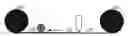
FIG. 1A is a perspective view of a roll of a shielding material.
FIG. 1B is a cross sectional view of a portion of the shielding material shown in FIG. 1A, taken along line 1B-1B.
FIG. 1C is a bottom plan view of a piece of shielding material as shown in FIG. 1B viewing a first end portion.
FIG. 1D is a top plan view of a piece of shielding material as shown in FIG. 1B viewing a second end portion.
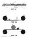
FIG. 2 is a cross sectional view of a surface and two units of shielding material applied thereto.
FIG. 3A is a schematic view showing a first action employed in making shielding material.
FIG. 3B is a schematic view showing a second action employed in making shielding material.
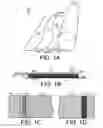
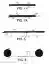
FIG. 4A is a cross sectional view of a portion of a first embodiment of an underlayment.
FIG. 4B is a cross sectional view of a portion of a second embodiment of an underlayment.
FIG. 5 is a cross sectional view of the embodiment shown in FIG. 4B in use.
FIG. 6 is a schematic view showing a method of making an underlayment.
DETAILED DESCRIPTION OF THE INVENTION
A preferred embodiment of the invention is now described in detail. Referring to the drawings, like numbers indicate like parts throughout the views. Unless otherwise specifically indicated in the disclosure that follows, the drawings are not necessarily drawn to scale. As used in the description herein and throughout the claims, the following terms take the meanings explicitly associated herein, unless the context clearly dictates otherwise: the meaning of “a,” “an,” and “the” includes plural reference, the meaning of “in” includes “in” and “on.”
As shown in FIGS. 1A-D, one embodiment of a shielding material 110 includes a non-conductive sheet material 120, such as masticated rubber, and a vapor barrier film 130 that is extruded onto a first side of the non-conductive sheet material 120. Adhered to a second side of the non-conductive sheet material 120 is a conductive sheet 140, including a conductive material such as copper, aluminum, lead or galvanized steel. An adhesive strip 134 is applied to the vapor barrier film 130. The adhesive strip 134 includes a peel-off protective cover film that prevents the adhesive strip 134 from sticking to other objects until the protective cover film has been removed.
In one embodiment, masticated rubber is used as the non-conductive sheet material 120 in which the masticated rubber has a thickness of approximately 3.0 mm. Such material is available from, for example, RB Rubber Products, Inc., 904 NE 10th Avenue, McMinnville, Oreg. 97128. Masticated rubber works well because it is robust enough to withstand soldering without unacceptable deformation, it will not transmit a static charge therethrough and it provides good sound insulation. Other materials (e.g. fiberglass) having these qualities could also be used as a non-conductive sheet material 120. In one embodiment, copper used as the conductive sheet 140 is about 0.007 inches thick and can be procured from one of many sheet copper sources. Typically, the copper sheet used in shielding walls should be at least 0.005 inches thick and the copper sheet used in shielding floors should be at least 0.007 inches thick. In many applications, there is no need for copper greater than 0.010 inches thick.
The conductive sheet 140 has a first end 142 and an opposite second end 146. The first end 142 is spaced apart from a first edge 124 of the non-conductive sheet 120. Also, a first portion 144 of the conductive sheet extends beyond the first edge 124 of the non-conductive sheet 120. The second end 146 of the conductive sheet 140 is parallel to a second edge 126 of the nonconductive sheet 120 so that a second portion 122 of the non-conductive sheet 120 extends beyond the second end 146 of the conductive sheet 140.
The vapor barrier film 130 includes a portion 132 that extends beyond the second edge 126 the non-conductive sheet material 120. The vapor barrier film 130 could include a material such as polyethylene, polypropylene, or combinations thereof.
The resulting shielding material 110 can be rolled into a roll (as shown in FIG. 1A), which can be cut into individual panels at the work site, or it can be delivered in individual flat panels (as shown in FIG. 1B-D).
In use, as shown in FIG. 2, individual panels of the shielding material can be brought together to form a continuous shielding surface 200 that covers a surface 10 such as a wall, a floor or a ceiling. A first panel 210a is applied to the surface 10 and then the peel-off protective cover film associated with the adhesive strip 134 of a second panel 210 is removed. The second panel 210b is then placed against the first panel 210a so that the adhesive strip 134 of the second panel adheres to the portion 132 of the vapor barrier 130 of the first panel 210a that extends beyond the second edge 126 the non-conductive sheet material 120, thus forming a continuous vapor seal across both panels. The first portion 144 of the conductive sheet 140 that extends beyond the first edge 124 of the non-conductive sheet 120 of the second panel 210b is placed against the conductive sheet 140 of the first panel 210a and a bead of solder 150 is melted therebetween so that the conductive sheet 140 of the first panel 210a is adhered to and is in continuous electrical communication with the conductive sheet 140 of the second panel 210b. Once the entire surface 10 is shielded, a decorative material (not shown) may be applied to the conductive sheet 140 for the sake of aesthetics. For example, wall material or flooring can be applied directly to the conductive sheet 140.
As shown in FIGS. 3A and 3B, one embodiment of a method of making a shielding material includes extruding a vapor barrier film 130 onto a non-conductive sheet material 120 as it is being unrolled from a first roll 320. The adhesive strip 134 is applied to the vapor barrier film 130 and the material rolled up into a second roll 302. The second roll 302 is then unrolled and an adhesive 310 (such as a pressure sensitive adhesive) from an adhesive roll 312 is applied thereto. The conductive sheet 140 from a roll 340 of conductive sheet material is applied to the adhesive 310 and the resulting shielding material 330 is either rolled up or cut into individual panels.
One embodiment, as shown in FIG. 4A, includes an underlayment material 400 that includes a sheet of masticated rubber 122 onto which a vapor barrier film 130 has been applied (e.g., extruded thereon).
In another embodiment, as shown in FIG. 4B, a flap of the vapor barrier film 132 extends from one edge 126 of the masticated rubber 122 and an adhesive strip is applied to the vapor barrier film at an opposite end 124 of the underlayment material 410. The flap 132 and adhesive strip 134 facilitate the sealing of the vapor barrier films 130 of two different sheets of underlayment material 410, as shown in FIG. 5.
In one embodiment, as shown in FIG. 6, the underlayment material 400 may be made by extruding a vapor barrier film 130 onto a sheet of masticated rubber 120 unrolled from a first roll 320. The resulting underlayment material 400 may then be rolled onto a second roll 600.
The above described embodiments, while including the preferred embodiment and the best mode of the invention known to the inventor at the time of filing, are given as illustrative examples only. It will be readily appreciated that many deviations may be made from the specific embodiments disclosed in this specification without departing from the spirit and scope of the invention. Accordingly, the scope of the invention is to be determined by the claims below rather than being limited to the specifically described embodiments above.
Claims
What is claimed is:1. A method of making an underlayment material, comprising the actions of:
a. extruding a vapor barrier film onto a sheet of masticated rubber to form the underlayment material; and
b. rolling the underlayment material into a roll.
2. The method of claim 1 further comprising the action of extending a flap of the vapor barrier film from a selected edge of the sheet of masticated rubber.
3. The method of claim 2, further comprising the action of applying an elongated adhesive strip onto a selected portion of the vapor barrier film.
Images & Drawings included:
Sources:
- United States Patent and Trademark Office - verify current appl. status at the USPTO↗
Similar patent applications:
- » 20170151768
Method for manufacturing an underlay material, and underlay material - » 20140335315
METHOD FOR MANUFACTURING AN UNDERLAY MATERIAL, AND UNDERLAY MATERIAL - » 20240352203
FILM-FORMING MATERIAL FOR SEMICONDUCTOR, MEMBER-FORMING MATERIAL FOR SEMICONDUCTOR, PROCESS MEMBER-FORMING MATERIAL FOR SEMICONDUCTOR, UNDERLAYER FILM-FORMING MATERIAL, UNDERLAYER FILM, AND SEMICONDUCTOR DEVICE - » 20110104484
Underlayment Material - » 20100314026
Window and door flashing, roofing underlayment, protection course, root block and sound control underlayment material products - » 20070077838
Multiple layer roofing underlayment material - » 20130108890
Target, An Underlayer Material For Co-Based Or Fe-Based Magnetic Recording Media, And Magnetic Recording Media - » 20080026663
Roofing underlayment material and process for making the same - » 20140131824
Magnetoresistive element using specific underlayer material - » 20180245349
Underlayment material
Recent applications in this class:
- » 20250115039 2025-04-10
DECORATIVE SHEET - » 20250108591 2025-04-03
MULTILAYER FILM AND PACKAGING FILM - » 20250100262 2025-03-27
GAS-BARRIER LAMINATE, PACKAGING FILM, PACKAGING CONTAINER, AND PACKAGED PRODUCT - » 20240246327 2024-07-25
MULTI-LAYER SELF-HEALING APPARATUSES AND METHODS - » 20240181765 2024-06-06
COATING MATERIALS FOR HIGH TEMPERATURE SURFACES - » 20230382092 2023-11-30
Vehicle Sheet Coating - » 20220297415 2022-09-22
BENDABLE LAMINATED FIBERBOARD - » 20220266581 2022-08-25
COATING AGENT FOR MODIFYING HEAT SEALABLE SUBSTRATE, LAMINATE, AND METHOD OF PRODUCING THE LAMINATE - » 20220063256 2022-03-03
FOLDABLE DISPLAY DEVICE - » 20210316542 2021-10-14
Laminate for molding
Recent applications for this Assignee:
- » 20230085014 2023-03-16
ARCHITECTURAL FLOORING UNDERLAYMENT - » 20220105701 2022-04-07
CUSHIONING FLOORING UNDERLAYMENT - » 20160016377 2016-01-21
Underlayment with of non-woven polyethylene mesh - » 20150047282 2015-02-19
Flooring and Underlayment including Extruded Sheet Material with Expanded Microspheres - » 20140023819 2014-01-23
Foam with Oriented Laminated Mesh Backing - » 20120237709 2012-09-20
Corrugated roof filler - » 20120073731 2012-03-29
Rolled shielding and insulating material - » 20110104484 2011-05-05
Underlayment Material - » 20110104421 2011-05-05
Rolled shielding and insulating material