Augmented velocity hydro-electric turbine generator
US20120098264A1
2012-04-26
13/341,035
2011-12-30
✅ Patent granted
US 8,405,240 B2
2013-03-26
-
-
Javaid Nasri
2031-12-30
Abstract:
This invention provides an augmented velocity hydraulic power generator comprised of an induced vortex in combination with other fluid velocity enhancement techniques to maximize power output enabling a minimal apparatus size and minimal or no environmental impact.
Applicant:
Interested in similar patents?
Get notified when new applications in this technology area are published.
Classification:
F03B13/264 » CPC main
Adaptations of machines or engines for special use; Combinations of machines or engines with driving or driven apparatus ; Power stations or aggregates characterised by using wave or tide energy using tide energy using the horizontal flow of water resulting from tide movement
F05B2240/133 » CPC further
Components; Stators to collect or cause flow towards or away from turbines with a convergent-divergent guiding structure, e.g. a Venturi conduit
F05B2240/97 » CPC further
Components; Mounting on supporting structures or systems on a submerged structure
F05B2250/15 » CPC further
Geometry two-dimensional spiral
F05B2250/50 » CPC further
Geometry Inlet or outlet
Y02E10/20 » CPC further
Energy generation through renewable energy sources Hydro energy
Y02E10/20 » CPC further
Energy generation through renewable energy sources Hydro energy
Y02E10/30 » CPC further
Energy generation through renewable energy sources Energy from the sea, e.g. using wave energy or salinity gradient
Y02E10/30 » CPC further
Energy generation through renewable energy sources Energy from the sea, e.g. using wave energy or salinity gradient
F01D15/10 IPC
Adaptations of machines or engines for special use; Combinations of engines with devices driven thereby Adaptations for driving, or combinations with, electric generators
F02C6/00 IPC
Plural gas-turbine plants; Combinations of gas-turbine plants with other apparatus ; Adaptations of gas- turbine plants for special use
H02P9/04 IPC
Arrangements for controlling electric generators for the purpose of obtaining a desired output Control effected upon non-electric prime mover and dependent upon electric output value of the generator
H02K7/18 IPC
Arrangements for handling mechanical energy structurally associated with dynamo-electric machines, e.g. structural association with mechanical driving motors or auxiliary dynamo-electric machines Structural association of electric generators with mechanical driving motors, e.g. with turbines
Description
This invention provides an augmented velocity hydraulic power generator comprised of an induced vortex in combination with other fluid velocity enhancement techniques to maximize power output enabling a minimal apparatus size and minimal or no environmental impact.
BACKGROUND OF THE INVENTION
The standard approach to hydro electric power generator focuses either on a large rotor diameter or on a large altitude change in order to maximize the power output. The resulting environmental impacts are therefore typically enormous and the initial installation is both prohibitively expensive and requires a long time.
SUMMARY OF THE INVENTION
This invention provides an improved hydro electric turbine power generator characterized by an augmented water velocity allowing the apparatus to remain small in size.
In the invention, the apparatus operates to augment the fluid velocity by:
-
- a. Inducing a vortex through a combination of spiraling helixes.
- b. A shrouded turbine casing.
- c. A central cone and tube.
The apparatus further includes a rotor set in motion by the relative velocity of the induced fluid vortex.
The apparatus includes a stator affixed to the turbine casing.
A preferred embodiment of this invention positions the central cone inside the turbine's casing and prolongs said cone by a tube parallel to said casing.
Embodiments of this invention may include shaping the central cone and tube in a half or full prolate spheroid.
It is thus a feature of at least one embodiment of the invention to generate the induced vortex with a spiraling helix located on the inner side of the turbine's casing and shroud and on the outer side of the central cone and tube.
Embodiments of this invention may include adjustments to the apparatus components' dimensions, proportions, and angles to optimize fluid velocity and power output.
The apparatus further includes means to maintain it at specific depth and placement in the flow through a combination of ballast, buoyancy tanks, tethers, and fins.
An embodiment of this invention may include use of lightweight construction materials such as plastics.
Embodiments of this invention may include modular expansions such as:
-
- a. A second turbine apparatus affixed to the rotor diametrically opposite to the first apparatus.
- b. Multiple apparatus or sections thereof, linked sequentially.
- c. Multiple apparatus or sections thereof, positioned parallely.
Preferred embodiments of the invention include features to minimize or eliminate the environmental impact such as:
-
- a. A small apparatus size compared to the industry's average obtained through the focus of enhanced fluid velocity.
- b. Protection grilles to deflect wildlife.
While the invention has been described in detail with specific reference to preferred embodiments thereof, it is understood that variations and modifications thereof may be made without departing from the spirit and scope of the invention.
BRIEF DESCRIPTION OF THE DRAWINGS
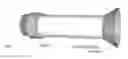
FIG. 1: Side view of an embodiment of the invention showing a shroud, turbine casing, stator and rotor.
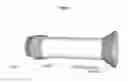
FIG. 2: Oblique view of an embodiment of the invention showing a shroud, turbine casing, stator and rotor along with a central cone and a spiraling helix located on the inner side of the turbine's casing.
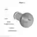
FIG. 3: Vertical view of a section of an embodiment of the invention showing a shroud, turbine casing, stator and rotor along with a central cone, central tube, a spiraling helix located on the outer side of said central cone and tube, and a spiraling helix located on the inner side of the turbine's casing.
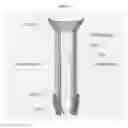
FIG. 4: Oblique view of an embodiment of the invention with adjusted components' dimensions, proportions, and angles showing a shroud, turbine casing, stator and rotor, along with a central cone and a spiraling helix located on the inner side of the turbine's casing.
Claims
What is claimed is:1. A hydro power turbine generator for generating electrical power from water flow characterized by an augmented water velocity through:
a. An induced vortex;
b. A shrouded turbine casing;
c. A central cone and tube;
d. A rotor set in motion by the relative velocity of the induced vortex;
e. A stator affixed to the turbine casing;
2. The apparatus according to claim 1 wherein said induced vortex is generated by a spiraling helix located on the inner side of the turbine's casing.
3. The apparatus according to claim 2 including provisions for a spiraling helix to be located on the inner side of the shroud.
4. The apparatus according to claim 1 wherein said central cone is prolonged by a tube parallel to said casing and are located inside the turbine's casing.
5. The apparatus according to claim 1 wherein said central cone and tube can have the shape of a half or full prolate spheroid.
6. The apparatus according to claim 4 wherein said induced vortex is generated by a spiraling helix wherein located on the outer side of said central cone and tube.
7. The apparatus according to claim 1 wherein the dimensions, proportions, and angles of the components may be adjusted to optimize fluid velocity and power output.
8. The apparatus according to claim 1 including means to enable buoyancy.
9. The apparatus according to claim 1 including means to anchor it to the bottom through one or more tethers.
10. The apparatus according to claim 1 including means to optimize its placement in the flow.
11. The apparatus according to claim 1 including provisions to use lightweight construction materials such as plastics.
12. The apparatus according to claim 1 including provisions for modular expansion where:
a. A second turbine apparatus can be affixed to the rotor diametrically opposite to the first apparatus;
b. Multiple apparatus or sections thereof can be linked sequentially, positioned parallely, or arranged in other relevant combinations;
13. The apparatus according to claim 1 including features to minimize or eliminate the environmental impact such as:
a. A small apparatus size;
b. Protection grilles to deflect wildlife;
Images & Drawings included:

Sources:
- United States Patent and Trademark Office - verify current appl. status at the USPTO↗
Recent applications in this class:
- » 20250003381 2025-01-02
TIDAL POWER GENERATING APPARATUS USING TIDE-INDUCING HYDRAULIC PIPELINE AND TIDAL POWER PIPELINE TURBINE - » 20240376859 2024-11-14
APPARATUS FOR PRODUCING ELECTRICAL ENERGY FROM WATER CURRENTS - » 20240263609 2024-08-08
Ocean wave and tidal current energy conversion system - » 20240141865 2024-05-02
POWER PLANT - » 20240125295 2024-04-18
SYSTEMS AND METHODS FOR ENERGY HARVEST - » 20230392573 2023-12-07
Tidal stream generation apparatus with pump - » 20230243331 2023-08-03
Turbine with dynamic blades - » 20230151792 2023-05-18
Large tidal current energy generating device and assembly platform thereof - » 20220403815 2022-12-22
Hydrokinetic telescopic turbine device - » 20220316441 2022-10-06
OCEAN CURRENT POWER PLANT