Frequency converter assembly
US20120099347A1
2012-04-26
13/253,396
2011-10-05
✅ Patent granted
US 8,780,591 B2
2014-07-15
-
-
Harry Behm | Matthew Grubb
Buchanan Ingersoll & Rooney PC
2032-07-19
Abstract:
A frequency converter assembly including an input for supplying electric power having an input frequency into the frequency converter assembly from a supply network, a direct voltage intermediate circuit having capacitor component, and at least one controllable switch. The switch being electrically positioned between the input and the direct voltage intermediate circuit. The assembly also includes an output for supplying electric power having an output frequency from the frequency converter assembly, and control component arranged to control the at least one controllable switch. The control component provides a recovery function to recover the capacitor component by supplying restricted recovery current from the supply network to the capacitor component through the at least one controllable switch, the control means also prevents supply of electric power from the direct voltage intermediate circuit towards the output during the recovery function.
Inventors:
- Osmo PASURI 11 🇫🇮 Ojakkala, Finland
- Jukka YLPPÖ 1 🇫🇮 Helsinki, Finland
- Jukka Ylppo 2 🇫🇮 Helsinki, Finland
Assignee:
- ABB OY 362 🇫🇮 Helsinki, Finland
Applicant:
Interested in similar patents?
Get notified when new applications in this technology area are published.
Classification:
H02M5/458 » CPC main
Conversion of ac power input into ac power output, e.g. for change of voltage, for change of frequency, for change of number of phases with intermediate conversion into dc by static converters using discharge tubes or semiconductor devices to convert the intermediate dc into ac using devices of a triode or transistor type requiring continuous application of a control signal using semiconductor devices only
H01G11/20 » CPC further
Hybrid capacitors, i.e. capacitors having different positive and negative electrodes; Electric double-layer [EDL] capacitors; Processes for the manufacture thereof or of parts thereof; Arrangements or processes for adjusting or protecting hybrid or EDL capacitors Reformation or processes for removal of impurities, e.g. scavenging
H02M5/4505 » CPC further
Conversion of ac power input into ac power output, e.g. for change of voltage, for change of frequency, for change of number of phases with intermediate conversion into dc by static converters using discharge tubes or semiconductor devices to convert the intermediate dc into ac using devices of a thyratron or thyristor type requiring extinguishing means using semiconductor devices only having a rectifier with controlled elements
H02M1/0032 » CPC further
Details of apparatus for conversion; Details of control, feedback or regulation circuits Control circuits allowing low power mode operation, e.g. in standby mode
H02M1/0085 » CPC further
Details of apparatus for conversion; Converters characterised by their input or output configuration Partially controlled bridges
Y02B70/10 » CPC further
Technologies for an efficient end-user side electric power management and consumption Technologies improving the efficiency by using switched-mode power supplies [SMPS], i.e. efficient power electronics conversion e.g. power factor correction or reduction of losses in power supplies or efficient standby modes
Y02E60/13 » CPC further
Enabling technologies; Technologies with a potential or indirect contribution to GHG emissions mitigation Energy storage using capacitors
Y02E60/13 » CPC further
Enabling technologies; Technologies with a potential or indirect contribution to GHG emissions mitigation Energy storage using capacitors
H02M5/453 IPC
Conversion of ac power input into ac power output, e.g. for change of voltage, for change of frequency, for change of number of phases with intermediate conversion into dc by static converters using discharge tubes or semiconductor devices to convert the intermediate dc into ac using devices of a triode or transistor type requiring continuous application of a control signal
H02M5/451 IPC
Conversion of ac power input into ac power output, e.g. for change of voltage, for change of frequency, for change of number of phases with intermediate conversion into dc by static converters using discharge tubes or semiconductor devices to convert the intermediate dc into ac using devices of a thyratron or thyristor type requiring extinguishing means using semiconductor devices only with automatic control of output voltage or frequency
Description
RELATED APPLICATION
This application claims priority under 35 U.S.C. §119 to Finnish Patent Application No. 20106087 filed on Oct. 21, 2010, the entire content of which is hereby incorporated by reference in its entirety.
FIELD
The disclosure relates to a frequency converter, such as a frequency converter assembly having a capacitor.
BACKGROUND INFORMATION
Known direct voltage intermediate circuits of a frequency converter are usually provided with capacitor means. The capacitor means can include electrolytic capacitors. Electrolytic capacitors can be specified for recovery if they have been inactive for a sufficiently long time. It is known to recover the electrolytic capacitors of a direct voltage intermediate circuit of a frequency converter by using a recovery circuit that includes a voltage source and a current-limiting resistor.
SUMMARY
An exemplary frequency converter assembly is disclosed. The assembly comprising an input for supplying electric power having an input frequency into the frequency converter assembly from a supply network, a direct voltage intermediate circuit having capacitor means, at least one controllable switch electrically positioned between the input and the direct voltage intermediate circuit, an output for supplying electric power having an output frequency from the frequency converter assembly, control means for controlling the at least one controllable switch, providing a recovery function to recover the capacitor means by supplying restricted recovery current from the supply network to the capacitor means through the at least one controllable switch, and preventing a supply of electric power from the direct voltage intermediate circuit towards the output during the recovery function; and clock means for measuring an inactive time of the capacitor means, wherein when an inactive time of the capacitor means measured by the clock means exceeds a predetermined recovery requirement limit value, the control means prevents the supply of electric power from the direct voltage intermediate circuit towards the output and allowing supply of electric power from the direct voltage intermediate circuit towards the output only after a recovery process has been completed.
An exemplary method of monitoring a recover requirement of a capacitor means in a frequency converter assembly including an input for supplying electric power having an input frequency into the frequency converter assembly from a supply network, a direct voltage intermediate circuit having a capacitor, at least one controllable switch electrically positioned between the input and the direct voltage intermediate circuit, an output for supplying electric power having an output frequency from the frequency converter assembly, a controller, and a clock is disclosed. The method comprises controlling the at least one controllable switch; executing a recovery process by supplying restricted recovery current from the supply network to the capacitor through the at least one controllable switch; preventing a supply of electric power from the direct voltage intermediate circuit towards an output of the frequency converter assembly during the recovery process; and allowing supply of electric power from the direct voltage intermediate towards an output only after the recovery process has been completed.
An exemplary frequency converter assembly is disclosed. The frequency converter assembly comprising an input for supplying electric power having an input frequency into the frequency converter assembly from a supply network; a direct voltage intermediate circuit having a capacitor; at least one controllable switch electrically positioned between the input and the direct voltage intermediate circuit; an output that supplies electric power having an output frequency from the frequency converter assembly; a controller that controls the at least one controllable switch, providing a recovery function to recover the capacitor by supplying restricted recovery current from the supply network to the capacitor through the at least one controllable switch, and prevents a supply of electric power from the direct voltage intermediate circuit towards the output during the recovery function; and a clock that measures an inactive time of the capacitor, wherein when an inactive time of the capacitor measured by the clock exceeds a predetermined recovery requirement limit value, the controller prevents the supply of electric power from the direct voltage intermediate circuit towards the output and allowing supply of electric power from the direct voltage intermediate circuit towards the output only after the recovery function has been completed.
BRIEF DESCRIPTION OF THE DRAWINGS
The disclosure will now be described in more detail in connection with preferred embodiments, referring to the attached drawings, of which:
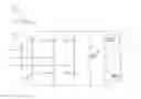
FIG. 1 shows a frequency converter assembly in accordance with an exemplary embodiment of the disclosure; and
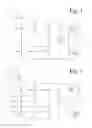
FIG. 2 shows a frequency converter assembly in accordance with another exemplary embodiment of the disclosure.
DETAILED DESCRIPTION
An exemplary embodiment of the present disclosure is directed to providing a frequency converter assembly having capacitor means. The capacitor means of which do not require the use of an external recovery circuit.
The disclosure is based on recovering capacitor means of a direct voltage intermediate circuit in a frequency converter assembly by supplying restricted recovery current from a supply network to the capacitor means through at least one controllable switch electrically positioned between the input and the direct voltage intermediate circuit of the frequency converter assembly while the frequency converter assembly automatically monitors the recovery requirement of the capacitor means and, if specified, prevents the frequency converter from being loaded before the recovery has been completed.
An advantage of an exemplary frequency converter assembly of the disclosure is that the frequency converter assembly is capable of automatically monitoring the recovery requirement of the capacitor means and to recover the converter means without an external voltage source.
FIG. 1 shows a frequency converter assembly in accordance with an exemplary embodiment of the disclosure. The frequency converter assembly of FIG. 1 includes an input, rectifier means 2, a direct voltage intermediate circuit 4, inverter means 6, control means 8, and an output. The input can be arranged to supply electric power having an input frequency into the frequency converter assembly. The rectifier means 2 (e.g. a rectifying circuit or rectifying component as desired) can be electrically positioned between the input and the direct voltage intermediate circuit 4 and can include rectifier switches T1, T2 and T3. Each of the rectifier switches T1, T2 and T3 can be a thyristor. The rectifier means 2 can be arranged to rectify electric power having an input frequency by using the rectifier switches T1 to T3. The direct voltage intermediate circuit 4 includes capacitor means C4 (e.g. a capacitor or other capacitive element as desired). The inverter means 6 are electrically positioned between the direct voltage intermediate circuit 4 and the output. The inverter means 6 (e.g. a power inverter) can be arranged to invert electric power of the direct voltage intermediate circuit 4 into electric power having an output frequency. The control means 8 (e.g. a processor, controller, or other control signal generating component as desired) can be arranged to control the operation of the frequency converter assembly. The output can be arranged to supply electric power having an output frequency out of the frequency converter assembly.
The control means 8 can be arranged to provide a recovery function (e.g., recovery process) in which the capacitor means C4 are recovered by supplying restricted recovery current from the supply network to the capacitor means C4 through the rectifier switches T1 to T3. The recovery current can be substantially lower than the rectifier current supplied through the rectifying switches T1 to T3 to the capacitor means while the frequency converter assembly supplies alternating current to the output at its nominal power. The control means 8 can be arranged, during the recovery function, to prevent supply of electric power from the direct voltage intermediate circuit 4 by keeping the controllable switches of the inverter means 6 in an open position.
The recovery function can include a phase angle charge period during which the control means 8 control the rectifier means 2 such that each rectifier switch T1 to T3 is in a conducting state only for part of such a period during which the voltage effective over the rectifier switch has a forward direction. In an exemplary embodiment, the rectifier means 2 can be controlled during the whole of the recovery function in such a way that each rectifier switch is in a conducting state only for part of such a period during which the voltage effective over the rectifier switch has a forward direction.
During the phase angle charge period, the trigger angle of each rectifier switch T1 to T3 can be constant or it can be varied. A trigger angle can refer to the moment when the thyristor is switched on, i.e. a switch-on pulse is given to the thyristor. Each rectifier switch T1 to T3 commutates, i.e. is switched off, when the voltage effective over the rectifier switch turns reverse. In an alternative embodiment, GTO thyristors can be used which can also be switched off controllably, i.e. switching off is also possible in cases where the voltage effective over the GTO thyristor has a forward direction.
In another exemplary embodiment in addition to a phase angle charge period, the recovery function can include a pulse charge period during which each of the rectifier switches T1 to T3 are alternately in an on-state and off-state such that during each on-state, the rectifier switch is in a conducting state over such a substantially whole period during which the voltage effective over the rectifier switch has a forward direction, and during each off-state, the rectifier switch is in a non-conducting state over such a whole period during which the voltage effective over the rectifier switch has a forward direction. In other words, in an on-state the rectifier switch can be kept in a conducting state as long as possible, and in an off-state the rectifier switch is not allowed to be conductive at all.
The control means 8 includes clock means 82 (e.g. a clock, timer, or other time measurement device as desired) arranged to measure the inactive time of the capacitor means C4. The inactive time of the capacitor means C4 can be a variable from which the recovery requirement of the capacitor means C4 can be deduced. The control means 8 can be arranged, in a situation where the inactive time of the capacitor means C4 measured by the clock means 82 exceeds a predetermined recovery requirement limit value, to prevent supply of electric power from the direct voltage intermediate circuit 4 towards the output and to allow supply of electric power from the direct voltage intermediate circuit 4 towards the output only after the recovery has been completed.
The inactive time of the capacitor means C4 measured by the clock means 82 starts to pass at the moment of the manufacture of the frequency converter assembly. In an alternative embodiment, the inactive time starts to pass at the moment of the manufacture of the capacitor means.
The clock means 82 can be arranged to reset the inactive time of the capacitor means C4 in response to each valid capacitor function. A valid capacitor function is a process that is sufficient to remove a need for recovery for a time period having a length of a recovery requirement limit value. A valid capacitor function can be a recovery process or a frequency converter function meeting predetermined terms of operation. A frequency converter function meeting predetermined terms of operation refers to an operating process of the frequency converter where the frequency converter assembly supplies load connected to the output for a sufficiently long time while the voltage of the capacitor means is sufficiently high during the operation.
The rectifier means 2 of the frequency converter assembly in FIG. 1 include a three-phase half-controlled bridge assembly the switches of which are thyristors. The half-controlled bridge assembly further includes diodes D4, D5 and D6. In an alternative embodiment, the rectifier means includes a fully controlled bridge assembly having six controllable switches. It should be understood that in both a half-controlled bridge assembly and in a fully controlled bridge assembly the thyristors can be replaced with other appropriate controllable switches, such as transistors.
The disclosure is not restricted to three-phase embodiments. In another exemplary embodiment of the disclosure, a one-phase frequency converter assembly includes rectifier means implemented with one controllable switch.
In frequency converter assemblies the frequency converter means can comprise several rectifier switches. The control means can be arranged to operate all rectifier switches to provide a recovery function. In an exemplary embodiment, the control means can be designed to control the rectifier switches in such a way that all phases of the supply network are loaded substantially equally. In another exemplary embodiment, however, the control means can be arranged to provide a recovery function by using only some of the rectifier switches of the rectifier means.
FIG. 2 shows a frequency converter assembly in accordance with another exemplary embodiment of the disclosure. As shown in FIG. 2, the frequency converter assembly includes network switch means (e.g., network switch) 10′, an input, rectifier means 2′, a direct voltage intermediate circuit 4′, inverter means 6′, control means 8′ and an output. The direct voltage intermediate circuit 4′ and the inverter means 6′ can be identical to the direct voltage intermediate circuit 4 and the inverter means 6, respectively, as shown in FIG. 1.
The rectifier means 2′ can be electrically positioned between the network switch means 10′ and the direct voltage intermediate circuit 4′. The rectifier means 2′ includes a diode bridge with diodes D1′, D2′, D3′, D4′, D5′ and D6′. The rectifier means 2′ can be arranged to rectify electric power having an input frequency by using the diodes D1′ to D6′. The rectifier means 2′ do not contain controllable switches.
The network switch means 10′ includes switch members S1′, S2′ and S3′, each of which is arranged to be connected to one phase of the supply network. The network switch means 10′ can be selectively arranged to connect the rectifier means 2′ to the electric supply network and to disconnect the rectifier means 2′ from the electric supply network. The control means 8′ can be arranged to provide a recovery function in which the capacitor means C4′ are recovered by supplying restricted recovery current from the supply network to the capacitor means C4′ through the network switch means 10′. The restricted recovery current is generated by keeping the switch members S1′, S2′ and S3′ alternately in closed and open positions.
The control means 8′ can be arranged to control the switch members S1′ to S3′ simultaneously in such a way that all switch members S1′ to S3′ are either in a closed position or in an open position. Alternatively, the control means 8′ can be arranged to control the switch members S1′ to S3′ individually, in which case some of the switch members S1′ to S3′ can be closed and some open at the same moment of time. If desired, the recovery function may also be carried out by using only one switch member of the three.
Thus, it will be appreciated by those skilled in the art that the present invention can be embodied in other specific forms without departing from the spirit or essential characteristics thereof. The presently disclosed embodiments are therefore considered in all respects to be illustrative and not restricted. The scope of the invention is indicated by the appended claims rather than the foregoing description and all changes that come within the meaning and range and equivalence thereof are intended to be embraced therein.
Claims
What is claimed is:1. A frequency converter assembly comprising:
an input for supplying electric power having an input frequency into the frequency converter assembly from a supply network;
a direct voltage intermediate circuit having capacitor means;
at least one controllable switch electrically positioned between the input and the direct voltage intermediate circuit;
an output for supplying electric power having an output frequency from the frequency converter assembly;
control means for controlling the at least one controllable switch, providing a recovery function to recover the capacitor means by supplying restricted recovery current from the supply network to the capacitor means through the at least one controllable switch, and preventing a supply of electric power from the direct voltage intermediate circuit towards the output during the recovery function; and
clock means for measuring an inactive time of the capacitor means, wherein when an inactive time of the capacitor means measured by the clock means exceeds a predetermined recovery requirement limit value, the control means prevents the supply of electric power from the direct voltage intermediate circuit towards the output and allowing supply of electric power from the direct voltage intermediate circuit towards the output only after the recovery function has been completed.
2. The frequency converter assembly according to claim 1, comprising:
rectifier means for rectifying electric power having an input frequency by using at least one rectifier switch, wherein the rectifier means is electrically positioned between the input and the direct voltage intermediate circuit, and includes the at least one rectifier switch, which is arranged as the at least one controllable switch.
3. The frequency converter assembly according to claim 1, comprising:
rectifier means for rectifying electric power having an input frequency, wherein the rectifier means is electrically positioned between the input and the direct voltage intermediate circuit; and
network switch means for selectively connecting the rectifier means to at least one phase of the supply network and for disconnecting the rectifier means from at least one phase of the supply network, wherein the network switch means is arranged as the at least one controllable switch.
4. The frequency converter assembly according to claim 1, wherein the recovery function comprises a phase angle charge period during which the at least one controllable switch is arranged to be in a conducting state only for part of a period during which effective voltage over the at least one controllable switch has a forward direction.
5. The frequency converter assembly according to claim 1, wherein the recovery function comprises a pulse charge period during which the at least one controllable switch is alternately in an on-state and in an off-state such that during each on-state the at least one controllable switch is in a conducting state over such a substantially whole period during which a voltage effective over the at least one controllable switch has a forward direction, and during each off-state the at least one controllable switch is in a non-conducting state over such a whole period during which the voltage effective over the at least one controllable switch has a forward direction.
6. The frequency converter assembly according to claim 1, wherein when the inactive time of the capacitor means, measured by the clock means, starts to pass at a moment of manufacture, the clock means resets the inactive time of the capacitor means in response to a valid capacitor function, wherein the moment of manufacture is a moment of manufacture of the capacitor means or the frequency converter assembly, and wherein the valid capacitor function is a recovery process or a frequency converter function meeting predetermined terms of operation.
7. The frequency converter assembly according to claim 6, wherein the frequency converter function meets the predetermined terms of operation when a voltage of the capacitor means is over a predetermined voltage limit value for a predetermined operating time.
8. The frequency converter assembly according to claim 1, wherein the capacitor means includes at least one electrolytic capacitor.
9. A method of monitoring a recovery requirement of a capacitor means in a frequency converter assembly including an input for supplying electric power having an input frequency into the frequency converter assembly from a supply network, a direct voltage intermediate circuit having a capacitor, at least one controllable switch electrically positioned between the input and the direct voltage intermediate circuit, an output for supplying electric power having an output frequency from the frequency converter assembly, a controller, and a clock, the method comprising:
controlling the at least one controllable switch;
executing a recovery process by supplying restricted recovery current from the supply network to the capacitor through the at least one controllable switch;
preventing a supply of electric power from the direct voltage intermediate circuit towards an output of the frequency converter assembly during the recovery process; and
allowing supply of electric power from the direct voltage intermediate towards an output only after the recovery process has been completed.
10. The method of claim 9, comprising:
rectifying electric power having an input frequency through at least one rectifier switch, which is arranged as the at least one controllable switch.
11. The method of claim 9, comprising:
selectively converting rectifier means of the frequency connector assembly to at least one phase of a supply network.
12. The method of claim 9, comprising:
disconnecting rectifier means of the frequency connector assembly from at least one phase of the supply network.
13. The method of claim 9, comprising:
resetting an inactive time of the capacitor means in response to a valid capacitor function, when the inactive time of the capacitor means starts to pass at a moment of manufacture.
14. A frequency converter assembly comprising:
an input for supplying electric power having an input frequency into the frequency converter assembly from a supply network;
a direct voltage intermediate circuit having a capacitor;
at least one controllable switch electrically positioned between the input and the direct voltage intermediate circuit;
an output that supplies electric power having an output frequency from the frequency converter assembly;
a controller that controls the at least one controllable switch, providing a recovery function to recover the capacitor by supplying restricted recovery current from the supply network to the capacitor through the at least one controllable switch, and prevents a supply of electric power from the direct voltage intermediate circuit towards the output during the recovery function; and
a clock that measures an inactive time of the capacitor, wherein when an inactive time of the capacitor measured by the clock exceeds a predetermined recovery requirement limit value, the controller prevents the supply of electric power from the direct voltage intermediate circuit towards the output and allowing supply of electric power from the direct voltage intermediate circuit towards the output only after the recovery function has been completed.
15. The frequency converter assembly according to claim 14, comprising:
a rectifier that rectifies electric power having an input frequency by using the at least one rectifier switch, wherein the rectifier is electrically positioned between the input and the direct voltage intermediate circuit, and includes at least one rectifier switch, which is arranged as the at least one controllable switch.
16. The frequency converter assembly according to claim 14, comprising:
a rectifier that rectifies electric power having an input frequency, wherein the rectifier is electrically positioned between the input and the direct voltage intermediate circuit; and
a network switch that selectively connects the rectifier to at least one phase of the supply network and that disconnects the rectifier from at least one phase of the supply network, wherein the network switch is the at least one controllable switch.
17. The frequency converter assembly according to claim 14, wherein the recovery function comprises a phase angle charge period during which the at least one controllable switch is arranged to be in a conducting state only for part of a period during which effective voltage over the at least one controllable switch has a forward direction.
18. The frequency converter assembly according to claim 14, wherein the recovery function comprises a pulse charge period during which the at least one controllable switch is alternately in an on-state and in an off-state such that during each on-state the at least one controllable switch is in a conducting state over such a substantially whole period during which a voltage effective over the at least one controllable switch has a forward direction, and during each off-state the at least one controllable switch is in a non-conducting state over such a whole period during which the voltage effective over the at least one controllable switch has a forward direction.
19. The frequency converter assembly according to claim 14, wherein when the inactive time of the capacitor, measured by the clock, starts to pass at a moment of manufacture, the clock resets the inactive time of the capacitor in response to a valid capacitor function, wherein the moment of manufacture is a moment of manufacture of the capacitor or the frequency converter assembly, and wherein the valid capacitor function is a recovery process or a frequency converter function meeting predetermined terms of operation.
20. The frequency converter assembly according to claim 19, wherein the frequency converter function meets the predetermined terms of operation when a voltage of the capacitor is over a predetermined voltage limit value for a predetermined operating time.
Images & Drawings included:
Sources:
- United States Patent and Trademark Office - verify current appl. status at the USPTO↗
Similar patent applications:
- » 20080013353
Frequency converter assembly and method of using frequency converter assembly - » 20200220472
Frequency converter, frequency converter assembly, and control method thereof - » 20080283514
Heated frequency converter assembly - » 20080310206
Method for controlling frequency converter unit, and frequency converter assembly - » 20120126645
Frequency converter assembly having converter housing attached through intermediate component to motor housing - » 20160128241
Cooling device for a frequency converter, converter assembly comprising said cooling device and refrigerating or conditioning plant comprising said converter assembly - » 20090039816
Assembly comprising a three-phase machine and a frequency converter
Recent applications in this class:
- » 20250274051 2025-08-28
MAGNETICALLY COUPLED CHARGING SYSTEM AND THE METHOD THEREOF - » 20250202378 2025-06-19
Configurable Drive System - » 20250158535 2025-05-15
DC BUS CAPACITOR ASSEMBLIES FOR VIENNA VFD IN AIR CONDITIONING SYSTEMS - » 20250158534 2025-05-15
POWER CONVERSION SYSTEM AND POWER UPDATE CONTROL METHOD - » 20250132688 2025-04-24
Voltage Driving Circuit and System and Household Appliance - » 20250030352 2025-01-23
VOLTAGE BOOST MODULE FOR A POWER CONVERTER - » 20240305211 2024-09-12
ARC FURNACLE FACILITY - » 20240275296 2024-08-15
CHARGING CURRENT METHOD, CHARGING CURRENT DEVICE, AND ELECTRONIC CONVERTER WITH THE CHARGING CURRENT DEVICE - » 20240235408 2024-07-11
HYBRID MODULAR MULTILEVEL RECTIFIER (HMMR) FOR HIGHLY DYNAMIC LOAD APPLICATIONS - » 20240097576 2024-03-21
DC POWER SUPPLY DEVICE, MOTOR DRIVING DEVICE, AND REFRIGERATION CYCLE APPLICATION APPARATUS
Recent applications for this Assignee:
- » 20230182882 2023-06-15
Draining arrangement of a propulsion unit - » 20220388622 2022-12-08
Method and a steering arrangement for turning a propulsion unit of a vessel - » 20220048607 2022-02-17
Cycloidal marine propulsion unit and a marine vessel equipped therewith - » 20220017197 2022-01-20
Drive arrangement for a cycloidal marine propulsion unit, a cycloidal marine propulsion unit and a method of operating such a drive arrangement - » 20220009608 2022-01-13
Marine propulsion unit - » 20210316832 2021-10-14
Propulsion unit - » 20190326083 2019-10-24
Electrical switch - » 20190326082 2019-10-24
Switching device - » 20190326073 2019-10-24
Electrical switch - » 20190300137 2019-10-03
Method and a control arrangement for controlling vibrations of a propulsion unit of a vessel