Method for the welding production of a large-dimensioned part from ductile iron by using laser-deposition-welded buffer materials and electric welding
US20120118860A1
2012-05-17
13/260,783
2010-03-31
✅ Patent granted
US 9,162,317 B2
2015-10-20
WO; PCT/EP2010/054321; 20100331
WO; WO2010/112552; 20101007
Dana Ross | Joseph Iskra
2032-11-01
Abstract:
A method for producing a part from ductile iron, including the steps of designing the part in such a way that the part is composed of a plurality of part components, producing the part components from ductile iron, providing the part components in pairs, depositing buffer material onto the rim edge of the first part component and onto the rim edge of the second part component by means of deposition welding, laying the second part component with the rim section thereof on the rim section of the first part component so that the rim edges lie against each other with the buffer materials thereof, and welding the rim sections, wherein the buffer material is selected in such a way that a structure change in the ductile iron material of the part components is prevented when the rim sections are welded.
Inventors:
- Karsten Niepold 5 🇩🇪 Mulheim, Germany
- Shilun Sheng 9 🇩🇪 Oberhausen, Germany
- Stefan Brussk 9 🇩🇪 Mulheim an der Ruhr, Germany
- Birgit Grüger 11 🇩🇪 Dortmund, Germany
- Michael Kretschmer 1 🇨🇳 Shanghai, China
- Claus Wilhelm 1 🇩🇪 Krefeld, Germany
Assignee:
- SIEMENS AKTIENGESELLSCHAFT 4,819 🇩🇪 Munchen, Germany
Applicant:
Interested in similar patents?
Get notified when new applications in this technology area are published.
Classification:
B23K26/323 » CPC further
Working by laser beam, e.g. welding, cutting or boring; Bonding taking account of the properties of the material involved involving parts made of dissimilar metallic material
B23K26/342 » CPC further
Working by laser beam, e.g. welding, cutting or boring; Laser welding for purposes other than joining Build-up welding
B23K26/346 » CPC further
Working by laser beam, e.g. welding, cutting or boring in combination with welding or cutting covered by groups - , e.g. in combination with resistance welding
B23K2101/001 » CPC further
Articles made by soldering, welding or cutting Turbines
B23K2103/06 » CPC further
Materials to be soldered, welded or cut; Iron or ferrous alloys Cast-iron alloys
B23K15/0073 » CPC main
Electron-beam welding or cutting; Welding; Seam welding with interposition of particular material to facilitate connecting the parts, e.g. using a filler
B23K15/0093 » CPC further
Electron-beam welding or cutting; Welding characterised by the properties of the materials to be welded
C23C28/02 » CPC further
Coating for obtaining at least two superposed coatings either by methods not provided for in a single one of groups - or by combinations of methods provided for in subclasses and or only coatings only including layers of metallic material
B23K35/0244 » CPC further
Rods, electrodes, materials, or media, for use in soldering, welding, or cutting characterised by mechanical features, e.g. shape for use in soldering, brazing Powders, particles or spheres; Preforms made therefrom
B23K35/0255 » CPC further
Rods, electrodes, materials, or media, for use in soldering, welding, or cutting characterised by mechanical features, e.g. shape for use in welding
B23K35/3033 » CPC further
Rods, electrodes, materials, or media, for use in soldering, welding, or cutting characterised by the composition or nature of the material; Selection of soldering or welding materials proper with the principal constituent melting at less than 1550 degrees C Ni as the principal constituent
C23C24/106 » CPC further
Coating starting from inorganic powder by application of heat or pressure and heat with intermediate formation of a liquid phase in the layer; Coating with metallic material, i.e. metals or metal alloys, optionally comprising hard particles, e.g. oxides, carbides or nitrides Coating with metal alloys or metal elements only
F01D25/24 » CPC further
Component parts, details, or accessories, not provided for in, or of interest apart from, other groups Casings ; Casing parts, e.g. diaphragms, casing fastenings
C23C28/023 » CPC further
Coating for obtaining at least two superposed coatings either by methods not provided for in a single one of groups - or by combinations of methods provided for in subclasses and or only coatings only including layers of metallic material only coatings of metal elements only
B23K26/34 IPC
Working by laser beam, e.g. welding, cutting or boring Laser welding for purposes other than joining
F05D2230/233 » CPC further
Manufacture essentially without removing material by permanently joining parts together by welding Electron beam welding
F05D2230/30 » CPC further
Manufacture with deposition of material
B23K28/00 » CPC further
Welding or cutting not covered by any of the preceding groups, e.g. electrolytic welding
C23C24/103 » CPC further
Coating starting from inorganic powder by application of heat or pressure and heat with intermediate formation of a liquid phase in the layer Coating with metallic material, i.e. metals or metal alloys, optionally comprising hard particles, e.g. oxides, carbides or nitrides
B23K9/04 IPC
Arc welding or cutting Welding for other purposes than joining, e.g. built-up welding
C23C24/10 IPC
Coating starting from inorganic powder by application of heat or pressure and heat with intermediate formation of a liquid phase in the layer
B23K26/32 IPC
Working by laser beam, e.g. welding, cutting or boring; Bonding taking account of the properties of the material involved
B23K35/30 IPC
Rods, electrodes, materials, or media, for use in soldering, welding, or cutting characterised by the composition or nature of the material; Selection of soldering or welding materials proper with the principal constituent melting at less than 1550 degrees C
B23K35/02 IPC
Rods, electrodes, materials, or media, for use in soldering, welding, or cutting characterised by mechanical features, e.g. shape
B23K15/00 IPC
Other welding or cutting; Working by laser beam
B23K15/00 IPC
Electron-beam welding or cutting
Description
CROSS REFERENCE TO RELATED APPLICATIONS
This application is the US National Stage of International Application No. PCT/EP2010/054321, filed Mar. 31, 2010 and claims the benefit thereof. The International Application claims the benefits of European Patent Office application No. 09004999.0 EP filed Apr. 3, 2009. All of the applications are incorporated by reference herein in their entirety.
FIELD OF INVENTION
The invention relates to a method for the production of a large-dimensioned part from ductile iron.
BACKGROUND OF INVENTION
Ductile iron is a cast iron comprising spheroidal graphite, with which large-dimensioned parts can be mass-produced economically. For example, the housing of a steam turbine is conventionally manufactured from ductile iron. The geometrical dimensions of a steam turbine in the upper power range, as are used for example for generating electricity in steam power plants, are however so large that problems can occur when casting ductile iron. For example, there is a high likelihood that nonuniformities and defects will occur in such a steam turbine housing, which compromise the strength of the steam turbine housing. Depending on the position in the part and the function of the positions affected, these nonuniformities and defects may be intolerable. There is therefore an upper limit on the maximum permissible size of housing parts made of ductile iron. A remedy would be provided by a housing part which is composed of a plurality of small pieces that are not critical in terms of casting technology. A prerequisite for this, however, would be that these pieces can form a housing when welded together. The pieces would need to be connected to one another by means of large-area welded connections, for which a suitable welding method would be necessary. However, no manufacturing method is known by which these types of large-area welded connections of ductile iron can be produced.
In general, nonuniformities and defects always occur in cast parts produced from ductile iron. The size and position of the nonuniformities and defects dictate whether the cast part in question must be discarded as a reject. For small local defects, repair welding methods are known. Such a repair welding method is, for example, cold welding with an iron-nickel alloy. However, the cold welding method produces a welded connection whose strength is less than the strength of the ductile iron. The cold welding method is therefore unsuitable for large-area welded connections. Another method is hot welding, although this can only be carried out by preheating of the part in the range of from 500° C. to 600° C., and subsequent heat re-treatment. Hot welding is therefore very complicated and generates distortion of the part, so that hot welding is unsuitable for large-area connection welding of ductile iron.
SUMMARY OF INVENTION
It is an object of the invention to provide a method for producing a part from ductile iron, the part having large dimensions but nevertheless a high strength.
The method according to the invention for producing a part from ductile iron comprises the steps: designing the part in such a way that the part is composed of a plurality of part components, which are placed on one another while forming partial joints and are dimensioned and configured so that they can be cast from ductile iron without critical defects in their material; producing the part components from ductile iron; providing the part components in pairs, a first of the part components and a second of the part components being intended for contiguous placement in which one of the partial joints is formed by a rim edge of a rim section of the first part component and a rim edge of a rim section of the second part component; depositing buffer material onto the rim edge of the first part component and onto the rim edge of the second part component by deposition welding; placing the second part component with its rim section onto the rim section of the first part component so that the rim edges lie on one another with their buffer materials; welding the rim sections so that the partial joint formed by the rim sections is welded and the first and second part components are thereby fastened to one another so that the first and second part components at least partially form the part; wherein the buffer material is selected so that a structural modification in the ductile iron material of the part components is prevented during the welding of the rim sections.
The part is therefore formed from the plurality of part components, unacceptable irregularities and defects in the ductile iron being prevented in the part components. For the design of the part, in principle no upper limit is therefore placed on the strength of the part owing to the use of ductile iron. Structural modification is intended in particular to mean hardening in the thermal influence zone and destruction of the basic material matrix by strong input of heat.
According to the invention, the part components are combined in a two-stage welding process, the buffer material first being deposited onto the rim edges prepared as weld bead flanks. The buffer material has a high nickel content and is adapted to the ductile iron and to the method for welding the rim sections. A large-area connecting weld of the ductile iron parts is made possible by the two-stage process. This welded connection has mechanical properties which are advantageously similar to those of the ductile iron. The part can therefore be designed with large dimensions, the part being constructed from small part components which are not critical in terms of casting technology. The likelihood of unacceptable irregularities and defects in the part is therefore low, and production of the large-dimensioned part is made possible.
The method according to the invention may furthermore be used for repairing the part, by separating a damaged section from the part and replacing it with a new section. The new section is welded into the existing part by using the method according to the invention.
The buffer material is preferably deposited containing nickel and/or in a plurality of layers. This creates a tempering effect of the layer respectively deposited previously or the thermal influence zone in the material of the part component. A laser powder deposition welding method is preferably used for the deposition welding. It is particularly preferable that a laser powder deposition welding method is used for the deposition welding of the buffer material onto the first part component and a low-energy shield gas welding method is used for the deposition welding of the buffer material onto the second part component, in such a way that no thermal influence zone is formed on the rim sections. In this way, the buffer material can be deposited onto the part components with a minimal effect on the material of the part components, as a result of which advantageous mechanical properties are achieved in the thermal influence zone of the deposition welding of the powder material.
During the welding of the rim sections, it is preferable to use a welding method having a high welding depth and a narrow welding pool, and a small thermal influence zone. The welding method is an electron beam welding method. The thickness of the powder material and the parameters of the electron beam welding method and of the laser powder deposition welding method are selected so that the thermal influence zone of the welding by the electron beam welding method is arranged in the buffer material.
BRIEF DESCRIPTION OF THE DRAWINGS
A preferred embodiment of a part produced by the method according to the invention will be explained below with the aid of the appended schematic drawings, in which:
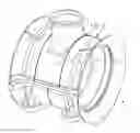
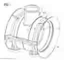
FIG. 1 shows a perspective view of an embodiment according to the invention of the part,
FIG. 2 shows a cross section through a rim section of a first part component of the part after a first production step and
FIG. 3 shows a cross section of the rim sections of the first part component and of a second part component of the part after a second production step.
DETAILED DESCRIPTION OF INVENTION
As can be seen in FIG. 1, a part is shown as a steam turbine low-pressure inner housing 1. The housing 1 is composed of a plurality of part components, in particular a first part component 2 and a second part component 3. The part components 2, 3 are placed on one another and form a partial joint 8. The part components 2, 3 are furthermore dimensioned and configured so that they can be cast from ductile iron without critical defects in their material.
The first part component 2 comprises a rim section 4, which is arranged immediately next to a rim section 5 of the second part component 3. The rim section 4 of the first part component 2 is delimited by a rim edge 6 which bears flush on a rim edge 7 that delimits the rim section 5 of the second part component 3. The partial joint 8 is thereby formed by the rim edges 6, 7.
During production of the housing 1, the first part component 2 and the second part component 3 are produced separately from ductile iron in a ductile iron casting method. In this case, there is a small risk that critical defects will be formed in the part components 2, 3.
In a first manufacturing step, the first part component 2 is provided. A first powder material layer 9 is deposited onto its rim edge 6 by a laser powder deposition welding method. A second powder material layer 10 is subsequently deposited onto the first powder material layer 9 by the laser powder deposition welding method. The thermal influence zone 11 of the first powder material layer 9 is arranged in the rim section 4 of the first part component 2. The thermal influence zone 12 of the second powder material layer 10 is arranged in the first powder material layer 9. The rim edge 7 of the rim section 5 of the second part component 3 is, like the rim edge 6, provided with a first powder material layer 9 and a second powder material layer 10. In a second manufacturing step, the part components 2 and 3 are placed on one another with their rim sections 4 and 5 so that the partial joint 8 is formed. The partial joint 8 is welded by an electron beam weld bead 13, the thermal influence zones 14 of the electron beam weld bead 13 being arranged in the buffer material layers.
Claims
1.-4. (canceled)
5. A method for the production of a part from ductile iron, comprising:
designing the part so that the part comprises a first part component and a second part component, which are placed on one another while forming a partial joint and are dimensioned and configured so that they are cast from ductile iron without critical defects in a material of the first part component and/or the second part component;
producing the first part component and the second part component from ductile iron;
providing the first part component and the second part component in a pair, the first part component and the second part component being intended for contiguous placement in which the partial joint is formed by a first rim edge of a first rim section of the first part component and a second rim edge of a second rim section of the second part component;
depositing a first buffer material onto the first rim edge of the first part component and a second buffer material onto the rim edge of the second part component by deposition welding;
placing the second part component with the second rim section onto the first rim section of the first part component so that the first and second rim edges lie on one another with the first and second buffer material; and
welding the first and second rim sections so that the partial joint formed by the first and second rim sections is welded and the first and second part components are thereby fastened to one another, as a result of which the first and second part components at least partially form the part,
wherein the first and second buffer materials are selected so that a structural modification in the ductile iron material of the first and part components is prevented during the welding of the first and second rim sections,
wherein a laser powder deposition welding method is used for the deposition welding,
wherein the welding is performed using an electron beam welding method,
wherein a thickness of the powder material and the parameters of the electron beam welding method and of the laser powder deposition welding method are selected so that a thermal influence zone of the welding by the electron beam welding method is arranged in the first and second buffer materials.
6. The method as claimed in claim 5, wherein the first and second buffer material is deposited comprising nickel and in a plurality of layers.
7. The method as claimed in claim 5, wherein the first and second buffer material is deposited comprising nickel or in a plurality of layers.
8. The method as claimed in claim 5, wherein a laser powder deposition welding method is used for the deposition welding of the first buffer material onto the first part component and a low-energy shield gas welding method is used for the deposition welding of the second buffer material onto the second part component, in such a way that no thermal influence zone is formed on the first and second rim sections.
9. The method as claimed in claim 5, wherein a welding method including a high welding depth and a narrow welding pool, and the small thermal influence zone, is used during the welding of the first and second rim sections.
Images & Drawings included:

Sources:
- United States Patent and Trademark Office - verify current appl. status at the USPTO↗
Recent applications in this class:
- » 20240109148 2024-04-04
METAL PACKERS - » 20230286076 2023-09-14
WELDING METHOD
Recent applications for this Assignee:
- » 20250291935 2025-09-18
Method, Apparatus and Device for Hardening Assets in OT System and Storage Medium and Computer Program Product - » 20250287560 2025-09-11
Parameterizing an Electronics Production Line - » 20250287419 2025-09-11
WLAN Communication Method, Access Point, Client, and Computing Device - » 20250284885 2025-09-11
Method and Apparatus for Adjusting Natural Language Sentence - » 20250283598 2025-09-11
Optimized Closed-Loop Control Of A Combustion Apparatus - » 20250279680 2025-09-04
Additively Manufactured Magnetic Lamination - » 20250272494 2025-08-28
Method and Apparatus for Generating Natural Language Sentence Describing Workflow - » 20250267066 2025-08-21
Network Configuration Method And Apparatus - » 20250266996 2025-08-21
Method, Device and System for Managing Carbon Data and Related Apparatus - » 20250265531 2025-08-21
Methods, Systems, Apparatus, Electronic Devices, And Storage Media For Evaluating Work Tasks