Device for preventing corrosion on a gas inlet nozzle during nitric acid condensation
US20120119395A1
2012-05-17
13/356,738
2012-01-24
✅ Patent granted
US 8,398,933 B2
2013-03-19
-
-
Jill Warden | Monzer Chorbaji
Collard & Roe, P.C.
2032-01-24
Abstract:
By a method and a device for preventing corrosion on and in the region of a gas inlet nozzle during nitric acid condensation, contact of the condensing gas with the nozzle and with the surroundings of the nozzle are supposed to be minimized. This is achieved in that the gas inlet nozzle has a sleeve on the inside in the transition region to the interior of the condenser, by which sleeve a gas inlet orifice in the form of an annular gap is formed, whereby the annular space is provided with at least one feed opening for secondary air, so that an enveloping flow of secondary air is produced around the entering NO gas.
Assignee:
- THYSSENKRUPP UHDE GMBH 147 🇩🇪 Dortmund, Germany
Applicant:
Interested in similar patents?
Get notified when new applications in this technology area are published.
Classification:
B01J19/26 » CPC main
Chemical, physical or physico-chemical processes in general; Their relevant apparatus Nozzle-type reactors, i.e. the distribution of the initial reactants within the reactor is effected by their introduction or injection through nozzles
B01J4/001 » CPC further
Feed or outlet devices; Feed or outlet control devices Feed or outlet devices as such, e.g. feeding tubes
B01J4/002 » CPC further
Feed or outlet devices; Feed or outlet control devices; Feed or outlet devices as such, e.g. feeding tubes Nozzle-type elements
C01B21/28 » CPC further
Nitrogen; Compounds thereof; Nitrogen oxides; Oxyacids of nitrogen; Salts thereof; Nitric oxide (NO); Preparation by catalytic or non-catalytic oxidation of ammonia Apparatus
B01J2219/00119 » CPC further
Chemical, physical or physico-chemical processes in general; Their relevant apparatus; Controlling or regulating processes; Controlling the temperature by indirect heating or cooling employing heat exchange fluids Heat exchange inside a feeding nozzle or nozzle reactor
Y10S423/06 » CPC further
Chemistry of inorganic compounds Temperature control
Y10S423/08 » CPC further
Chemistry of inorganic compounds Corrosion or deposition inhibiting
Y10T137/6525 » CPC further
Fluid handling; With heating or cooling of the system Air heated or cooled [fan, fins, or channels]
F28B3/00 IPC
Condensers in which the steam or vapour comes into direct contact with the cooling medium
F27D1/12 IPC
Casings; Linings; Walls; Roofs incorporating cooling arrangements
F27B14/10 IPC
Crucible or pot furnaces; Details peculiar to crucible or pot furnaces Crucibles
B08B3/00 IPC
Cleaning by methods involving the use or presence of liquid or steam
F26B19/00 IPC
Machines or apparatus for drying solid materials or objects not covered by groups -
F16K49/00 IPC
Means in or on valves for heating or cooling
Description
CROSS REFERENCE TO RELATED APPLICATIONS
This application is a divisional of and Applicant claims priority under 35 U.S.C. §§120 and 121 of parent U.S. patent application Ser. No. 12/449,531 filed on Aug. 12, 2009, which application is a national stage application under 35 U.S.C. §371 of PCT/EP2007/010062 filed on Nov. 21, 2007, which claims priority under 35 U.S.C. §119 of German Application No. 10 2007 006 889.3 filed on Feb. 13, 2007, the disclosures of each of which are hereby incorporated by reference. The international application under PCT article 21(2) was not published in English.
BACKGROUND OF THE INVENTION
1. Field of the Invention
This invention relates to a method and a device for preventing corrosion on and in the region of a gas inlet nozzle during nitric acid condensation.
2. The Prior Art
In nitric acid facilities that operate under high pressure >10 bar, the condensation point of the acid is correspondingly high, at about 120° C. This leads to higher corrosive attacks on the gas nozzles on the inlet side, especially in the first gas-cooling stage. Increased acid condensation occurs especially at the transition zones between the cooled jacket and the hot nozzle wall, followed by revaporization. The acid, then concentrated except for the azeotrope, leads to severe rates of erosion of the stainless steel material to the point of leakage.
SUMMARY OF THE INVENTION
This is the starting point for the invention, the task of which consists in minimizing the contact of the condensing gas with the nozzle and its surroundings.
This problem is solved according to the invention by a method of the type indicated initially, in that the gas inlet nozzle has a sleeve on the inside in the transition region to the interior of the condenser, by which sleeve a gas inlet orifice in the form of an annular gap is formed, whereby the annular space is provided with at least one feed opening for secondary air, so that an enveloping flow of secondary air is produced around the entering NO gas.
Providing a veil of secondary air on the inside wall of the gas inlet nozzle prevents, or minimizes to a substantial degree, the contact of the NO gas with this inside wall, and thereby it is correspondingly protected.
According to the invention, such an enveloping flow can be produced by blowing in the secondary air through a plurality of inlet holes on the gas inlet nozzle.
An important benefit of the method of procedure according to the invention consists in the fact that only a portion of the secondary air supplied to the condenser by way of a bypass is needed for this protective measure, so that no process changes at all are necessary because of the method of procedure of the invention.
Since the entering gas has about a 17% fraction of water, which is brought about primarily by the water of combustion, and the condensation point of the water and of the acid then immediately formed depends on the partial pressure of the water, the condensation starts at higher temperatures, in particular at higher gas pressures. The partial pressure of the water vapor is then correspondingly reduced by the proposed measure, by the veil and thus by the addition of air, and the condensing gas is kept completely away from the wall of the pipe, so that no condensation, and thus no acid formation, can any longer occur on the inside of the nozzle conducting the pressure.
According to the invention, the above problem can also be solved by a device that is characterized in that the gas inlet nozzle has a sleeve on the inside in the transition region to the interior of the condenser, by which a gas inlet orifice in the form of an annular gap is formed, whereby the annular space is equipped with at least one feed orifice for secondary air.
As already explained above, the secondary air displaces the aggressive condensing gas completely from the gap between the inside wall of the nozzle and the additional pipe, with the result that no acid can be formed here. This protects the inner nozzle (liner) formed by the pipe from attack by acid, since the wall temperature can always be kept above the condensation temperature by the hot secondary air.
A feed nozzle for different gas streams to a mixing chamber with a central pipe through which a first stream flows, which pipe is surrounded by at least one jacket pipe forming an annular space with the feed of a second gas stream, is itself known; reference is made here to U.S. Pat. No. 3,467,498 or in comparable construction to U.S. Pat. No. 3,586,055, both of which are concerned with preparing pigmented metal oxide. Preventing contact of an aggressive gas stream with components to be protected against corrosion by means of an enveloping flow is not addressed here.
Embodiments of the invention are discussed below.
In this connection, it can be provided that a plurality of secondary air inlet orifices are provided upstream in the direction of flow of the entering NO gas, on the gas inlet nozzle, whereby it is practical if these secondary air inlet orifices are linked by way of a ring line and connected with the source of secondary air, as is likewise provided in a further embodiment of the invention.
It is advantageous for the secondary air to be connected to the secondary air source of a high-pressure nitric acid facility.
BRIEF DESCRIPTION OF THE DRAWINGS
Other characteristics, details, and advantages of the invention are evident from the following description and with reference to the drawing. The drawing shows:
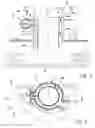
FIG. 1 a sectional drawing from the region of a gas inlet nozzle in a nitric acid condenser, and
FIG. 2 a top view, in partial section, of the gas inlet nozzle, along Line II-II in FIG. 1.
DETAILED DESCRIPTION OF PREFERRED EMBODIMENTS
The condenser labeled in general as 1 has a condenser jacket 2 with a cooled jacket region 3, through which a gas inlet nozzle for the NO gas labeled as 4 passes. The cooling tubes of the acid condenser are labeled in general as 5 in FIG. 1, and are partially cut away for reasons of the illustration.
As shown in FIG. 1, the gas inlet nozzle 4 has a safety nozzle 6 in the transition region to the inside of the condenser 1, which nozzle forms an annular space labeled 7, in the manner of a gap, toward the inside wall 4a of the gas inlet nozzle 4. The annular space 7 is connected with secondary air inlet nozzles 8 distributed around its circumference on a ring line 9, which in turn is connected, for example, to the secondary air source of a high-pressure nitric acid facility, which is not shown in detail in the figures. An enveloping flow 11 is formed by the secondary air inlet, indicated by the arrow 10 in FIG. 1, between the inside wall 4a of the gas inlet nozzle 4 and the safety nozzle or sleeve 6.
Since the secondary air generally has such a high temperature that there is no condensation of the NOx gas on the safety nozzle or sleeve 6, the safety nozzle 6 is not in danger of corrosion.
Naturally, the exemplary embodiment of the invention as described can also be modified in multiple respects, without departing from the basic concept. Thus, the invention is not limited in particular to proportions and distribution of the secondary air inlet nozzles and their distribution around the circumference. This also applies to the size and diameter of the corresponding components and to the gap width of the gap 7 through which the secondary air flows.
Claims
What is claimed is:1. An apparatus comprising:
(a) a nitric acid condenser comprising a gas inlet nozzle; and
(b) a sleeve on an inside portion of the gas inlet nozzle in a transition region to an interior portion of the condenser to form a gas inlet orifice comprising an annular gap having an annular space, the annular space comprising at least one feed opening for secondary air.
2. The apparatus according to claim 1, wherein a plurality of secondary air inlet orifices are provided on the gas inlet nozzle upstream in a direction of flow of NO gas entering the gas inlet nozzle.
3. The apparatus according to claim 2, wherein the secondary air inlet orifices are linked by way of a ring line and are connected with a source of secondary air.
4. The apparatus according to claim 3, wherein the secondary air inlet nozzles are connected with the secondary air source of a high-pressure nitric acid facility.
Images & Drawings included:

Sources:
- United States Patent and Trademark Office - verify current appl. status at the USPTO↗
Similar patent applications:
Recent applications in this class:
- » 20250242326 2025-07-31
Carbon Black Reactor Having Cooling Function - » 20250186964 2025-06-12
APPARATUS AND METHOD FOR PRODUCING CATALYST PARTICLES - » 20250083120 2025-03-13
FEEDSTOCK REACTOR AND METHOD OF COOLING A FEEDSTOCK REACTOR - » 20240269644 2024-08-15
JET IMPINGEMENT REACTOR - » 20240075451 2024-03-07
SYSTEM AND PROCESS WITH ASSISTED GAS FLOW INSIDE A REACTION CHAMBER - » 20240001330 2024-01-04
REACTOR - » 20230398514 2023-12-14
HYDROTHERMAL REACTOR SYSTEMS AND METHODS - » 20230191358 2023-06-22
Exhaust gas aftertreatment systems - » 20230122570 2023-04-20
Initiator injection into high pressure LDPE reactors - » 20220347648 2022-11-03
Apparatus for preparing oligomer
Recent applications for this Assignee:
- » 20250289724 2025-09-18
AMMONIA CONVERTER FOR VARYING PARTIAL LOAD OPERATION - » 20250282629 2025-09-11
PROCESS FOR OPERATING AN AMMONIA SYNTHESIS WITH VARYING PLANT UTILIZATION - » 20250188005 2025-06-12
THERMAL COUPLING OF A PLANT FOR PREPARING 1,2-DICHLOROETHANE TO A PLANT FOR THERMAL DESALINATION (OF SEA WATER) - » 20250171303 2025-05-29
NITRIC ACID PLANT FOR PRODUCING NITRIC ACID - » 20250154016 2025-05-15
AMMONIA SYNTHESIS AND UREA SYNTHESIS WITH REDUCED CO2 FOOTPRINT - » 20250145482 2025-05-08
AMMONIA SYNTHESIS AND UREA SYNTHESIS WITH REDUCED CO2 FOOTPRINT - » 20250136526 2025-05-01
PLA COATING OF FERTILISERS - » 20250122075 2025-04-17
METHOD FOR SYNTHESIZING AMMONIA AND PLANT FOR PRODUCING AMMONIA - » 20250100874 2025-03-27
PROCESS AND PLANT FOR PRODUCING HYDROGEN FROM AMMONIA - » 20250059031 2025-02-20
METHOD FOR RECOVERING PROCESS CONDENSATE