Systems, Devices, A Systems,Devices, And/Or Methods For Managing Traffic
US20120121326A1
2012-05-17
13/383,884
2009-09-29
Abstract:
Certain exemplary embodiments can provide a system, machine, device, and/or manufacture comprising a traffic separating median barrier comprising: a barrier body having a substantially uniform cross section along a longitudinally extending direction, said barrier body defining a body length extending along said longitudinally extending direction, a body width orthogonal to said body length, and a body height orthogonal to said body length and said body width, said barrier body terminating in a first barrier end region and a second barrier end region, said first barrier end region comprising a female interlocking structure attached to said barrier body, said second barrier end region comprising a male interlocking structure attached to said barrier body, said female interlocking structure adapted to interlock with said male interlocking structure.
Inventors:
- Michael L. Budd, SR. 4 🇺🇸 Bridgewater, VA, United States
- Roy D. Simmons, JR. 4 🇺🇸 Dayton, VA, United States
Assignee:
- Conmat Group, Inc. 4 🇺🇸 Harrisonburg, VA, United States
Interested in similar patents?
Get notified when new applications in this technology area are published.
Classification:
E01F15/088 » CPC main
Safety arrangements for slowing, redirecting or stopping errant vehicles, e.g. guard posts or bollards; Arrangements for reducing damage to roadside structures due to vehicular impact; Continuous barriers extending along roads or between traffic lanes essentially made of walls or wall-like elements ; Cable-linked blocks Details of element connection
E01F15/083 » CPC further
Safety arrangements for slowing, redirecting or stopping errant vehicles, e.g. guard posts or bollards; Arrangements for reducing damage to roadside structures due to vehicular impact; Continuous barriers extending along roads or between traffic lanes essentially made of walls or wall-like elements ; Cable-linked blocks characterised by the use of a specific material using concrete
E01F15/00 IPC
Safety arrangements for slowing, redirecting or stopping errant vehicles, e.g. guard posts or bollards; Arrangements for reducing damage to roadside structures due to vehicular impact
Description
BRIEF DESCRIPTION OF THE DRAWINGS
A wide variety of potential practical and useful embodiments will be more readily understood through the following detailed description of certain exemplary embodiments, with reference to the accompanying exemplary drawings in which:
FIG. 1A is a left end view of an exemplary barrier, illustrating an exemplary female interlocking structure;
FIG. 1B is a side view of the exemplary barrier shown in FIG. 1A;
FIG. 1C is a right end view of the exemplary barrier shown in FIG. 1A, illustrating an exemplary male interlocking structure;
FIG. 2 is a side view of the exemplary male and female interlocking structures and an exemplary interconnecting structure between the exemplary male and female interlocking structures;
FIG. 3 is a plan view of the exemplary male and female interlocking structures and an exemplary interconnecting structure between the exemplary male and female interlocking structures;
FIG. 4 is a plan cross-sectional view taken at section A-A of FIG. 1B and showing an exemplary male interlocking structure of one exemplary barrier interlocked with an exemplary female interlocking structure of an adjacent exemplary barrier;
FIGS. 5A and 5B show side and plan views, respectively, of an exemplary male interlocking structure;
FIGS. 6A and 6B show side and plan views, respectively, of an exemplary female interlocking structure;
FIG. 7 is a plan view of an exemplary group of connected exemplary barriers; and
FIG. 8 is a side view of an exemplary group of connected exemplary barriers.
DETAILED DESCRIPTION
Median barriers, which typically are relatively heavy devices that are frequently utilized for separating lanes of traffic from other lanes of traffic, construction work, etc. The barriers typically must be sufficiently heavy such that, if accidentally contacted by a moving vehicle, they will prevent the moving vehicle from leaving its lane, thereby protecting construction workers, pedestrians, and/or other lanes of traffic on the other side of the median barrier.
Pre-cast reinforced concrete can be used to form median barriers. Yet to be most effective, there is a need to ensure that vehicles generally cannot pass through or substantially move a median barrier and thereby create a hazard to the adjacent lane of traffic, constructions workers, pedestrians, etc.
Median barriers can have certain resistance to movement caused by the weight of the barrier and the static coefficient of friction between the lower surface of the barrier and the roadway and/or other surface upon which the barrier is located. Because this coefficient of friction is generally fixed, the resistance to lateral movement is generally proportional to the weight of the barrier. For the convenience of construction crews, temporary barriers are often constructed with a length on the order of 12 feet, although longer or shorter barriers can be provided if the need arises (if, for example, it were necessary to have barriers around a very sharp curve, shorter barriers might permit the outer edge of the curve to be lined with barriers without the barriers intruding on the roadway). Unfortunately, as a barrier becomes smaller, its weight typically becomes less and, thus, its resistance to lateral movement becomes less. This can create challenges when a need arises for both a resistance to impact-generated movement and a non-linear grouping of barriers.
One answer to the problem of barriers being shifted under vehicle impact is to involve the weight and mass of adjacent barriers such that several adjacent barriers must be moved in the event of a vehicle impact, thereby providing greater resistance to lateral movement of the struck barrier. Exemplary embodiments of such an approach are described here, where similar exemplary structures are similarly numbered among the various figures in the drawings.
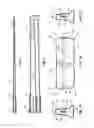
FIG. 1B is a side view of an exemplary embodiment of a precast concrete barrier 10, showing longitudinally-extending top face 61, longitudinally-extending bottom face 62, end face 63, and end face 64. FIG. 1A is a side view of an exemplary female interlocking structure 14 on one end of barrier 10, and showing longitudinally-extending side faces 65 and 66. FIG. 1C is an end view of the other end of the barrier in FIG. 1B showing an exemplary male interlocking structure 12 located thereon. Depicted in phantom lines are an exemplary connection structure for interconnecting the male interlocking structure 12 with the female interlocking structure 14 internal to barrier 10.
Barrier 10 can be constructed of reinforced concrete having a minimum compressive strength at the age of approximately 28 days of approximately 4,000 psi. Reinforcement in barrier 10 can conform to ASTM A615, Grade 60. The standard length for an exemplary barrier can be approximately 12 feet with the male portion protruding from the end of the barrier by approximately 1⅞ (1.875) inches. The width of the body of the exemplary barrier shown in FIGS. 1A and 1C can be approximately 24 inches and the height can be approximately 32 inches. The body can be cast directly and/or in multiple units. For example, if a length less than approximately 12 feet be desirable, such length can be cast directly, and if a section longer than approximately 12 feet be needed, it can be cast as one unit, or as two or more units.
The interrelationship of an exemplary male interlocking structure 12 and an exemplary female interlocking structure 14 with a respective exemplary barrier 10 is shown in FIG. 4. As can be seen, either the male end of an elevated leftmost barrier or the female end of an elevated right-hand barrier can be lowered vertically so as to interengage the web 20 and flange 22 of male interlocking structure 12 with the slot 30 and tube 26 of female interlocking structure 14. As shown, in certain exemplary embodiments, there can be a gap and/or separation of approximately 0 inches to approximately 4 inches, including all values (e.g., approximately 0.76, 1, 1.252, 1.5, 2, etc., inches) and subranges therebeween, between barriers when the barriers are pulled as far apart as possible while in the interconnected state. This gap can permit one barrier to be canted with respect to another so as to permit a curve in a line of barriers without disengaging the interlocking portions of the barriers. Furthermore, the barriers can continue to form a structural interconnection between adjacent barriers when forming a curve or other non-linear pattern along a roadway, median, etc. This spacing also can permit barriers to be interengaged and/or interlocked when there is a vertical displacement, i.e., the line of barriers begins to go up and/or over a hill and/or otherwise encounters a change in grade and/or elevation.
Male interlocking structure 12 and female interlocking structure 14 can be respectively interconnected internally to barrier 10. FIGS. 2 and 3 show these interlocking structures. Each of reinforcing bars 40 and 42 can comprise a section of, for example, number 5 or number 6 rebar measuring approximately 11 foot 8 inches. Note that the number of reinforcing bars shown in the drawings is conceptual only, and the actual number implemented in a particular barrier can depend on the design requirements of that barrier.
These interconnecting reinforcing bars 40 and/or 42 can be welded to anchor bars 24 and 28 that can be connected to male interlocking structure 12 and female interlocking structure 14, respectively. Note that the number of anchor bars shown in the drawings is conceptual only, and the actual number implemented in a particular barrier can depend on the design requirements of that barrier. In certain exemplary embodiments, interconnecting rebar 40 and/or 42 merely can be wired to be substantially adjacent corresponding anchor bars 24 and/or 28 as shown in the phantom lines of FIGS. 1A and 1B. This can facilitate precise alignment of male interlocking structure 12 and/or female interlocking structure 14 while the concrete is poured and/or cured. The overlap in which interconnecting reinforcing bars 40 and/or 42 coextend with anchor rods 24 and/or 28 of male interlocking structure 12 and/or female interlocking structure 14 can be equal to approximately 40 diameters of the larger reinforcing bar, which can provide substantially the same structural strength as welding the bars together.
As shown in FIG. 1B, edges and/or major surface intersections (e.g., top face to end face, bottom face to end face, side face to end face, etc.) 51, 52, 53, and/or 54 can be sharp, perpendicular, notched, angled, beveled, chamfered, rounded, and/or arced. By notching, angling, beveling, chamfering, rounding, arcing, and/or otherwise causing edges and/or major surface intersections 51, 52, 53, and/or 54 (e.g., by beveling (chamfering) and/or cutting back the intersections by approximately 0.75 inches) to transition from the longitudinally-extending major faces to the end faces of the barriers by other than perpendicular intersections, interconnected barriers 10 can have greater freedom to be positioned at an angle with respect to each other's longitudinal axis as measured in a substantially vertical plane without substantial compromise of the strength and/or crash-worthiness of barrier 10.
FIG. 4 is a plan cross-sectional view taken at section A-A of FIG. 1B. As shown edges and/or major face intersections (e.g., right side surface to end surface, left side surface to end surface, top face to end face, etc.) 56, 57, 58, and/or 59 can be sharp, perpendicular, notched, angled, beveled, chamfered, rounded, and/or arced. By notching, angling, beveling, chamfering, rounding, arcing, and/or otherwise causing edges and/or major face intersections 56, 57, 58, and/or 59 to transition from the side and/or longitudinally extending major surfaces to the end surfaces of the barriers by other than simple perpendicular intersections, interconnected barriers can have greater freedom to be positioned at an angle with respect to each other's longitudinal axis as measured in a substantially horizontal plane.
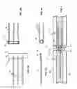
FIGS. 5A and 5B show the details of an exemplary embodiment of the male interlocking structure 12 comprising web 20 and flange 22, respectively. In certain exemplary embodiments, web 20 can have the form of a substantially rectangular plate that can extend substantially vertically for approximately 6 inches to approximately 18 inches, including all values (e.g., approximately 7.5, 8, 10, 12, 13.75, 15, etc. inches) and subranges therebetween, and/or can extend substantially longitudinally from an end face of barrier 10 by approximately 2 inches to approximately 8 inches, including all values (e.g., approximately 2.5, 3, 3.75, 5.543, 6, 7.25, etc., inches) and subranges therebetween. Flange 22 can have the form of a substantially rectangular plate that can: be positioned substantially orthogonally to web 20, extend along any portion of the substantially vertical length of web 20, and/or have a width of approximately 1 inch to approximately 3 inches, including all values (e.g., approximately 1.364, 1.75, 2, 2.5, etc., inches) and subranges therebetween. In certain exemplary embodiments, web 20 can be welded to flange 22 to form a “T” shape (although the combination can be cast, forged, and/or otherwise machined in one substantially monolithic piece).
Welded to web 20 can be a number of anchoring bars 24 that can serve to aid in anchoring web 20 in the end of concrete barrier 10. Reinforcing bars 24 can be, for example, number 6 A706 rebar. In the exemplary embodiment shown in FIGS. 5A and 5B, the rebar can measure from approximately 2 feet to approximately 5 feet in length, including all values (e.g., 2.5, 2.78, 3, 3.777, 4, etc., feet) and subranges therebetween, and/or can be welded to the web 20 where it is in contact therewith. Web 20 and/or flange 22 can measure approximately one-half inch thick and/or can be standard steel, e.g., A36 (FYE close 36 ksi), structural steel, and/or high strength structural steel, e.g., A500 (FYE close 39 ksi).
Referencing FIGS. 6A and 6B, female interlocking structure 14 can be a tube 26 which can have any desired cross-sectional shape (e.g., triangular, square, rhomboid, rectangular, hexagonal, round, etc.), can be constructed of structural steel, can measure, for example, approximately one-half inch thick and approximately 4 inches square, can extend for a predetermined portion of the height of the barrier, and/or can be positioned in a predetermined position with respect to the height of the barrier (e.g., substantially centered, offset by approximately 2 inches from center, raised approximately 10 inches from the bottom surface of the barrier, etc.). The longitudinal axis of tube 26 can be substantially orthogonal with the longitudinally extending direction of the barrier. Substantially parallel with the longitudinally extending direction of the barrier and/or affixed and/or welded to the sides of the substantially vertically oriented tube 26 can be sections of anchoring bars 28, which can be approximately 2 feet in length. Anchoring bars 28 can serve to anchor tube 26 in the reinforced concrete of the median barrier. In the portion of tube 26 external to the concrete material of median barrier 10 can be a vertically extending slot 30 that can have a width greater than the thickness of web 20, such as approximately 1 inch. The edges of tube 26 defined by slot 30 can be perpendicular, angled, beveled, chamfered, arced, rounded, etc.
In certain exemplary embodiments, flange 22 can be in the form of a steel structural tube having smaller outside longitudinal cross-sectional dimension(s) than the inside longitudinal cross-sectional dimension(s) of tube 26. For example, if tube 26 has a circular longitudinal cross-section with an inner diameter of 4 inches, flange 22 can also have a circular longitudinal cross-section, but with an outer diameter of less than 4 inches, so that flange 22 is free to move longitudinally with respect to tube 26. As another example, if tube 26 has a square longitudinal cross-section with an inner dimensions of 3 inches by 3 inches, flange 22 can also have a square longitudinal cross-section, but with outer dimensions of less than 3 inches, so that flange 22 is free to move longitudinally with respect to tube 26. The intersection of web 20 with flange 22 would likely form a cross-sectional shape of other than a “T” shape in such embodiments. Nevertheless, because the width of slot 30 can be less than the dimension of flange 22 measured in the same direction, relative non-longitudinal movement between the flange and tube of two interlocked barriers would be substantially limited, effectively making the two barriers substantially inseparable in response to vehicular impact.
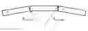
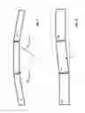
FIG. 7 is a plan view of an exemplary group of interconnected exemplary barriers 72, 74, and 76, and shows that such barriers can form a curve in a substantially horizontal plane, that curve having, for example, a minimum radius of approximately 50 feet to infinity, including all values (e.g., 63.7, 85, 102.33, 125, 160, 200, 400, 800, etc.), and subranges therebetween, when measured to the innermost surface (or outermost surface if desired) of the barriers with respect to an axis of the curve. Thus, any adjacent pair of such barriers can form an angle with respect to each other's longitudinal axis, as measured in a substantially horizontal plane, of approximately 0 to approximately 15 degrees, which is equivalent to approximately 0 to approximately 16.7 percent, including all values (e.g., approximately 5, 6.1, 7.5, 8.04, 10, 12.5, etc., degrees, and/or approximately 5.6, 6.5274, 8.5, 9, 11.25, 14, etc., percent) and subranges (e.g., between 3.1 and 7.94 degrees, 5 degrees to 10 percent, at least 5 degrees, greater than 6 percent, etc.) therebetween.
FIG. 8 is a side view of an exemplary group of interconnected exemplary barriers 82, 84, and 86, and shows that such barriers can accommodate a grade change (Δ) in a substantially vertical plane, that grade change having an angle measuring approximately 0 degrees to approximately 4 degrees. Thus, any adjacent pair of such barriers can form an angle with respect to each other's longitudinal axis, as measured in a substantially vertical plane, of approximately 0 to approximately 4 degrees, which is equivalent to approximately 0 to approximately 4.5 percent, including all values and subranges therebetween, such as 2.75 degrees, 3.8 percent, greater than 3 degrees, etc.
For any substantially identical pair of interconnected barriers, the maximum possible degree (or percent) of the angle between the longitudinal axes of those barriers' bodies can be affected by any combination of:
-
- the primary materials, properties, and/or dimensions of barrier 10 and/or its components;
- how far web 20 extends from the end face of barrier 10 (i.e., the longitudinally-extending width of web 20);
- the dimensions, thickness, and/or height of web 20 and/or flange 22;
- the position of web 20 and/or flange 22 with respect to the major faces of barrier 10;
- the dimensions, thickness, height, and/or position of tube 26;
- the dimensions and/or position of the slot and/or space defined by tube 20 in which web 20 and/or flange 22 can move;
- the dimensions, position, and/or distance of male interlocking structure and/or female interlocking structure with respect to one or more longitudinally-extending major faces of barrier 10; and/or
- the technique via which, one or more longitudinally-extending major faces transitions to one or both end faces of barrier 10 and/or the degree to which the otherwise perpendicular intersections of such faces are angled, beveled, notched, arced, rounded, trimmed, cutback, removed, and/or smoothed, etc.;
- etc.
In certain exemplary embodiments, interconnecting bars and/or anchor bars can be mechanically connected, e.g., through U-shaped bolts and/or extending through holes in the structural tube and/or web to aid in connecting the interlocking components to their respective ends of the pre-cast concrete median barrier. In certain exemplary embodiments, different numbers of interconnecting bars and/or anchor bars and/or different sizes of bars can be used to maintain a secure connection between the interlocking structures and their respective barriers.
In certain exemplary embodiments, different arrangements of webs and/or flanges can be used as long as the web can be inserted vertically into the slots of the female interlocking structure and the flange is wider than the slot so as to prevent disengagement in any direction other than a substantially vertical direction.
Median barriers constructed in accordance with certain exemplary embodiments disclosed herein have met or exceeded, in independent crash tests, the Federal Highway Administration standards for median barriers and in particular the American Association of State Highway and Transportation Officials (AASHTO) Manual for Assessing Safety Hardware (MASH) Test Level-3 (TL-3). These tests confirm that certain exemplary interlocked barriers did not separate and/or become disengaged even though impacted by a 2.205 ton pickup traveling at 63.3 miles per hour at a 25.66 incidence angle with the barrier.
Federal Highway Administration approval of a barrier in accordance with certain exemplary embodiments was granted on 17 Jul. 2009.
Thus, certain exemplary embodiments can provide a system, machine, device, and/or manufacture comprising, and/or a method for creating and/or using, a traffic separating median barrier comprising:
-
- a barrier body comprised of an elongated concrete material, said barrier body defined by a substantially uniform cross section along a longitudinally extending direction, said barrier body defining a body length extending along said longitudinally extending direction, a body width orthogonal to said body length, and a body height orthogonal to said body length and said body width, said barrier body terminating in a first barrier end region and a second barrier end region, said first barrier end region comprising a female interlocking structure attached to said barrier body, said second barrier end region comprising a male interlocking structure attached to said barrier body, said female interlocking structure adapted to interlock with said male interlocking structure;
- said female interlocking structure comprising a substantially open-ended tube having a longitudinal axis extending substantially parallel to said body height, said tube defining a slot having a slot width substantially parallel to said body width and having a slot height substantially parallel to said body height; and
- said male interlocking structure comprising a web having a web thickness extending substantially parallel to said slot width and measuring less than said slot width, said web extending from said barrier end in a direction parallel to said body length and attached to a flange having a longitudinal axis extending substantially parallel to a longitudinal axis of said web and a major surface extending substantially perpendicular to a major surface of said web, said flange having a flange width greater than said slot width;
- a plurality of interconnecting rods, each of said interconnecting rods connected to each of said interlocking structures and extending longitudinally through said barrier body;
- a first plurality of interlock anchor rods, each of said first plurality of interlock anchor rods interconnecting with one of said interlocking structures and extending in said longitudinally extending direction a distance of at least 40 diameters of said interconnecting rods; and/or
- a first plurality of interlock anchor rods, each of said first plurality of interlock anchor rods extending in said longitudinally extending direction, interconnecting with one of said interlocking structures, and overlapping an adjacent one of said interconnecting rods by a distance of at least 40 diameters of said interconnecting rods;
- wherein:
- for any substantially identical pair of said barriers, a longitudinal axis of a barrier body of a first barrier from said pair is capable of being angled horizontally by at least 6 degrees, or vertically by at least 3 degrees, with respect to a longitudinal axis of a barrier body of a second adjacent barrier from said pair when a male interlocking structure of said first barrier is interlocked with a female interlocking structure of said second barrier by a web of said first barrier extending through a slot of said second barrier and a flange of said first barrier located within a metal tube of said second barrier;
- said concrete material is precast concrete;
- said concrete material is reinforced precast concrete;
- said tube is at least partially embedded in said concrete material;
- said web and said flange interconnect to form a T-shaped cross-section;
- said web height is substantially equivalent to said slot height;
- said male interlocking structure is comprised of metal and said female interlocking structure is comprised of metal;
- said male interlocking structure extends less than 18 inches in a direction parallel to said body height;
- said female interlocking structure extends less than 18 inches in a direction parallel to said body height;
- each of said barrier end regions comprises an end face that transitions to a longitudinal face, a top face, and a bottom face of said barrier via a plurality of chamfers;
- each of said barrier end regions comprises an end face that transitions to a longitudinal face, a top face, or a bottom face of said barrier via a corresponding chamfer;
- each of said barrier end regions comprises an end face that transitions to a longitudinal face, top face, or bottom face of said barrier via a corresponding substantially beveled edge;
- each of said barrier end regions comprises an end face that transitions to a longitudinal face, top face, or bottom face of said barrier via a corresponding substantially rounded edge;
- said first barrier is incapable of separation from said second barrier when interlocked therewith and subjected to a vehicle impact load sufficient to otherwise move said first barrier when not interlocked with said second barrier;
- said barrier is adapted to satisfy all current crash test requirements of the United States Federal Highway Administration (FHWA); and/or
- said barrier is adapted to satisfy all current crash test requirements of the American Association of State Highway and Transportation Officials (AASHTO) Manual for Assessing Safety Hardware (MASH) Test Level-3 (TL-3).
Definitions
When the following terms are used substantively herein, the accompanying definitions apply. These terms and definitions are presented without prejudice, and, consistent with the application, the right to redefine these terms via amendment during the prosecution of this application or any application claiming priority hereto is reserved. For the purpose of interpreting a claim of any patent that claims priority hereto, each definition in that patent functions as a clear and unambiguous disavowal of the subject matter outside of that definition.
-
- a—at least one.
- activity—an action, act, step, and/or process or portion thereof.
- adapted—suitable, fit, and/or capable of performing a specified function.
- adjacent—close to; lying near; next to; adjoining, and/or within a horizontal radius of approximately 0.5 to approximately 6 inches of, including all values and subranges therebetween.
- all—every.
- anchor—(v) to hold, fix, and/or secure; (n) a device adapted to hold, fix, and/or secure another.
- and/or—either in conjunction with or in alternative to.
- angled—forming or set at an angle
- apparatus—an appliance or device for a particular purpose
- associate—to join, connect together, and/or relate.
- at least—not less than.
- attach—to fasten, secure, couple, and/or join.
- axis—a straight line about which a body or geometric object rotates or can be conceived to rotate and/or a center line to which parts of a structure or body can be referred.
- barrier—a structure that impedes and/or obstructs free movement.
- beveled edge—an edge of a structure that is not perpendicular (but instead often at 45 degrees) to the faces of the structure.
- body—a main and/or central part.
- bottom—a lowermost point.
- can—is capable of, in at least some embodiments.
- capable—having the requisite structural qualities for.
- cause—to bring about, provoke, precipitate, produce, elicit, be the reason for, result in, and/or effect.
- chamfer—(n) a beveled edge connecting two perpendicular surfaces; (v) to cut a bevel on and/or shape to a bevel.
- comprised—included in; a part of.
- comprising—including but not limited to.
- concrete—a hard, strong construction material comprising sand, conglomerate gravel, pebbles, broken stone, or slag, in a mortar or cement matrix.
- configure—to make suitable or fit for a specific use or situation.
- connect—to join or fasten together.
- connected—physically linked.
- containing—including but not limited to.
- convert—to transform, adapt, and/or change.
- corresponding—related, assoicated, accompanying, similar in purpose and/or position, conforming in every respect, and/or equivalent and/or agreeing in amount, quantity, magnitude, quality, and/or degree.
- coupleable—capable of being joined, connected, and/or linked together.
- coupling—linking in some fashion.
- crash test—a form of destructive testing involving vehicular impact that is usually performed to ensure compliance with safe design standards.
- create—to bring into being.
- cross-section—a section formed by a plane cutting through an object at a right angle to an axis.
- current—contemporaneous to the present time (i.e., as of the effective filing date of the relevant priority patent application).
- define—to establish the outline, form, and/or structure of.
- degree—a measure of arcs and plane angles and representing 1/360 of a full rotation.
- device—a machine, manufacture, and/or collection thereof.
- diameter—a thickness of an elliptical object.
- direction—a spatial relation between something and a course along which it points and/or moves; a distance independent relationship between two points in space that specifies the position of either with respect to the other; and/or a relationship by which the alignment and/or orientation of any position with respect to any other position is established.
- distance—a measure of physical and/or logical separation.
- each—every one of a group considered individually.
- edge—an often sharp intersection of two, often substantially planar, surfaces.
- elongated—drawn out, made spatially longer, and/or having more length than width.
- embed—to implant, fix, and/or set securely and/or deeply.
- end—an extremity and its vicinity of something that has length; a terminus.
- end region—a portion in the vicinity of an terminus.
- equivalent—the same as, equal to.
- extend—to reach spatially outward, stretch, cover, and/or span.
- extending—existing, located, placed, and/or stretched lengthwise.
- face—a significant and/or prominent surface of an object.
- female—a structure adapted to receive an corresponding extending structure.
- flange—a protruding rim, edge, rib, collar, tube, etc.
- form—to create.
- from—used to indicate a source.
- further—in addition.
- generate—to create, produce, give rise to, and/or bring into existence.
- greater—larger and/or more than.
- having—including but not limited to.
- height—a measurement of the extent of something along an, often substantially vertical, dimension.
- horizontal—parallel to and/or in the plane of the horizon.
- identical—alike and/or very similar.
- impact—to have an effect and/or influence on.
- incapable—not capable.
- inch—a unit of length equal to one twelfth of a foot.
- including—including but not limited to.
- initialize—to prepare something for use and/or some future event.
- install—to connect or set in position and prepare for use.
- interconnect—to connect to one another.
- interlock—to unite or join closely so as to substantially restrict and/or prevent relative movement therebetween in at least one direction.
- length—a longest dimension of something and/or the measurement of the extent of something along its greatest dimension.
- less than—having a measurably smaller magnitude and/or degree as compared to something else.
- load—a substantial force.
- located—situated in a particular spot and/or position.
- longitudinal—of and/or relating to a length; placed and/or running lengthwise.
- longitudinal axis—a straight line defined parallel to an object's length and passing through a centroid of the object.
- major—relatively great in size or extent.
- male—a structure adapted to extend and to be received by a corresponding female structure.
- material—a substance and/or composition.
- may—is allowed and/or permitted to, in at least some embodiments.
- measure—(n) a quantity ascertained by comparison with a standard. (v) to physically sense, and/or determine a value and/or quantity of something relative to a standard.
- metal—any of a category of electropositive elements that usually have a shiny surface, are generally good conductors of heat and electricity, and can be melted or fused, hammered into thin sheets, or drawn into wires.
- method—one or more acts that are performed upon subject matter to be transformed to a different state or thing and/or are tied to a particular apparatus, said one or more acts not a fundamental principal and not pre-empting all uses of a fundamental principal.
- move—to change a position and/or place.
- not—a negation of something.
- open—not closed.
- orthogonal—perpendicular.
- overlap—to extend over and cover a part of.
- pair—a quantity of two of something.
- parallel—of, relating to, or designating lines, curves, planes, and/or or surfaces everywhere equidistant and/or an arrangement of components in an electrical circuit that splits an electrical current into two or more paths.
- partially—to a degree, but not necessarily totally.
- perpendicular—intersecting at and/or forming a substantially right angle.
- plurality—the state of being plural and/or more than one.
- precast—molded and/or cast at a prior time.
- predetermined—established in advance.
- project—to calculate, estimate, or predict.
- provide—to furnish, supply, give, and/or make available.
- receive—to get, take, acquire, and/or obtain.
- recommend—to suggest, praise, commend, and/or endorse.
- rectangular—defined by four substantially right angles.
- reinforce—to give added strength and/or support.
- request—to express a desire for and/or ask for.
- requirement—a documented necessity, mandatory specification, and/or prerequisite condition.
- rod—an elongated structure having a cross-section taken perpendicular to its longitudinal axis that is substantially elliptical and/or circular shaped.
- rounded—having a surface that is curved, arced, and/or not flat.
- satisfy—to fulfill, carry out, effect, and/or complete.
- select—to make a choice or selection from alternatives.
- separate—(n) distinct; (v) to disunite, space, set, or keep apart and/or to be positioned intermediate to.
- separation—removal, disengagement, and/or substantial displacement.
- set—a related plurality.
- slot—a narrow opening and/or aperture; and/or an opening having a longer length than a width of the opening.
- structure—a device.
- substantially—to a considerable, large, and/or great, but not necessarily whole and/or entire, extent and/or degree.
- sufficient—to a degree necessary to achieve a predetermined result.
- support—to bear the weight of, especially from below.
- surface—the outer boundary of an object and/or a material layer constituting and/or resembling such a boundary.
- system—a collection of mechanisms, devices, machines, articles of manufacture, processes, data, and/or instructions, the collection designed to perform one or more specific functions.
- terminate—to end.
- thickness—a dimension through an object.
- through—in one side and out the opposite or another side of, across, among, and/or between.
- top—an uppermost point.
- traffic—a flow of vehicles and/or pedestrians.
- traffic separating median—a strip and/or space that divides, segregates, and/or sets apart opposing lanes of vehicles and/or pedestrians.
- transform—to change in measurable: form, appearance, nature, and/or character.
- transition—to pass, change, convert, and/or transform from one place and/or state to another.
- T-shaped—shaped to resemble the upper case letter T.
- tube—an elongate member having a longitudinal axis and defining a longitudinal cross-section resembling any substantially closed shape such as, for example, a circle, a non-circle such as an oval (which generally can include a shape that is substantially in the form of an obround, ellipse, limaçon, cardioid, cartesian oval, and/or Cassini oval, etc), and/or a polygon such as a triangle, rectangle, square, parallelogram, rhomboid, pentagon, hexagon, the shape of the letter “D”, the shape of the letter “P”, etc. Thus, a right circular cylinder is one form of a tube, an elliptic cylinder is another form of a tube having an elliptical longitudinal cross-section, and a generalized cylinder is yet another form of a tube.
- uniform—non-varying.
- vehicle—any type of land surface mobile transport, such as a car, motorcycle, truck, trailer, bus, tram, scooter, bicycle, ATV, golf cart, unmanned vehicle, robot, taxiing airplane, etc.
- vertical—substantially perpendicular to horizontal.
- via—by way of and/or utilizing.
- web—a substantially rectangular plate.
- when—at a time.
- wherein—in regard to which; and; and/or in addition to.
- width—a measurement of the extent of something along an, often substantially horizontal, dimension.
- with respect to—in relation to.
- within—inside.
Note
Various substantially and specifically practical and useful exemplary embodiments of the claimed subject matter, are described herein, textually and/or graphically, including the best mode, if any, known to the inventors for carrying out the claimed subject matter. Variations (e.g., modifications and/or enhancements) of one or more embodiments described herein might become apparent to those of ordinary skill in the art upon reading this application. The inventors expect skilled artisans to employ such variations as appropriate, and the inventors intend for the claimed subject matter to be practiced other than as specifically described herein. Accordingly, as permitted by law, the claimed subject matter includes and covers all equivalents of the claimed subject matter and all improvements to the claimed subject matter. Moreover, every combination of the above described elements, activities, and all possible variations thereof are encompassed by the claimed subject matter unless otherwise clearly indicated herein, clearly and specifically disclaimed, or otherwise clearly contradicted by context.
The use of any and all examples, or exemplary language (e.g., “such as”) provided herein, is intended merely to better illuminate one or more embodiments and does not pose a limitation on the scope of any claimed subject matter unless otherwise stated. No language in the specification should be construed as indicating any non-claimed subject matter as essential to the practice of the claimed subject matter.
Thus, regardless of the content of any portion (e.g., title, field, background, summary, description, abstract, drawing figure, etc.) of this application, unless clearly specified to the contrary, such as via explicit definition, assertion, or argument, or clearly contradicted by context, with respect to any claim, whether of this application and/or any claim of any application claiming priority hereto, and whether originally presented or otherwise:
-
- there is no requirement for the inclusion of any particular described or illustrated characteristic, function, activity, or element, any particular sequence of activities, or any particular interrelationship of elements;
- no characteristic, function, activity, or element is “essential”;
- any elements can be integrated, segregated, and/or duplicated;
- any activity can be repeated, any activity can be performed by multiple entities, and/or any activity can be performed in multiple jurisdictions; and
- any activity or element can be specifically excluded, the sequence of activities can vary, and/or the interrelationship of elements can vary.
The use of the terms “a”, “an”, “said”, “the”, and/or similar referents in the context of describing various embodiments (especially in the context of the following claims) are to be construed to cover both the singular and the plural, unless otherwise indicated herein or clearly contradicted by context. The terms “comprising,” “having,” “including,” and “containing” are to be construed as open-ended terms (i.e., meaning “including, but not limited to,”) unless otherwise noted.
Moreover, when any number or range is described herein, unless clearly stated otherwise, that number or range is approximate. Recitation of ranges of values herein are merely intended to serve as a shorthand method of referring individually to each separate value falling within the range, unless otherwise indicated herein, and each separate value and each separate subrange defined by such separate values is incorporated into the specification as if it were individually recited herein. For example, if a range of 1 to 10 is described, that range includes all values therebetween, such as for example, 1.1, 2.5, 3.335, 5, 6.179, 8.9999, etc., and includes all subranges therebetween, such as for example, 1 to 3.65, 2.8 to 8.14, 1.93 to 9, etc.
When any claim element is followed by a drawing element number, that drawing element number is exemplary and non-limiting on claim scope. No claim of this application is intended to invoke paragraph six of 35 USC 112 unless the precise phrase “means for” is followed by a gerund.
Any information in any material (e.g., a United States patent, United States patent application, book, article, etc.) that has been incorporated by reference herein, is only incorporated by reference to the extent that no conflict exists between such information and the other statements and drawings set forth herein. In the event of such conflict, including a conflict that would render invalid any claim herein or seeking priority hereto, then any such conflicting information in such material is specifically not incorporated by reference herein.
Accordingly, every portion (e.g., title, field, background, summary, description, abstract, drawing figure, etc.) of this application, other than the claims themselves, is to be regarded as illustrative in nature, and not as restrictive, and the scope of subject matter protected by any patent that issues based on this application is defined only by the claims of that patent.
Claims
What is claimed is:1. A traffic separating median barrier comprising:
a barrier body comprised of an elongated concrete material, said barrier body defined by a substantially uniform cross section along a longitudinally extending direction, said barrier body defining a body length extending along said longitudinally extending direction, a body width orthogonal to said body length, and a body height orthogonal to said body length and said body width, said barrier body terminating in a first barrier end region and a second barrier end region, said first barrier end region comprising a female interlocking structure attached to said barrier body, said second barrier end region comprising a male interlocking structure attached to said barrier body, said female interlocking structure adapted to interlock with said male interlocking structure;
said female interlocking structure comprising a substantially open-ended tube having a longitudinal axis extending substantially parallel to said body height, said tube defining a slot having a slot width substantially parallel to said body width and having a slot height substantially parallel to said body height; and
said male interlocking structure comprising a web having a web thickness extending substantially parallel to said slot width and measuring less than said slot width, said web extending from said barrier end in a direction parallel to said body length and attached to a flange having a longitudinal axis extending substantially parallel to a longitudinal axis of said web and a major surface extending substantially perpendicular to a major surface of said web, said flange having a flange width greater than said slot width;
wherein:
for any substantially identical pair of said barriers, a longitudinal axis of a barrier body of a first barrier from said pair is capable of being angled horizontally by at least 6 degrees, or vertically by at least 3 degrees, with respect to a longitudinal axis of a barrier body of a second adjacent barrier from said pair when a male interlocking structure of said first barrier is interlocked with a female interlocking structure of said second barrier by a web of said first barrier extending through a slot of said second barrier and a flange of said first barrier located within a tube of said second barrier.
2. A traffic separating median barrier according to claim 1, further comprising:
a plurality of interconnecting rods, each of said interconnecting rods connected to each of said interlocking structures and extending longitudinally through said barrier body.
3. A traffic separating median barrier according to claim 1, further comprising:
a plurality of interconnecting rods, each of said interconnecting rods connected to each of said interlocking structures and extending longitudinally through said barrier body; and
a first plurality of interlock anchor rods, each of said first plurality of interlock anchor rods interconnecting with one of said interlocking structures and extending in said longitudinally extending direction a distance of at least 40 diameters of said interconnecting rods.
4. A traffic separating median barrier according to claim 1, further comprising:
a plurality of interconnecting rods, each of said interconnecting rods connected to each of said interlocking structures and extending longitudinally through said barrier body; and
a first plurality of interlock anchor rods, each of said first plurality of interlock anchor rods extending in said longitudinally extending direction, interconnecting with one of said interlocking structures, and overlapping an adjacent one of said interconnecting rods by a distance of at least 40 diameters of said interconnecting rods.
5. A traffic separating median barrier according to claim 1, wherein:
said concrete material is precast concrete.
6. A traffic separating median barrier according to claim 1, wherein:
said concrete material is reinforced precast concrete.
7. A traffic separating median barrier according to claim 1, wherein:
said tube is at least partially embedded in said concrete material.
8. A traffic separating median barrier according to claim 1, wherein:
said web and said flange interconnect to form a T-shaped longitudinal cross-section.
9. A traffic separating median barrier according to claim 1, wherein:
said web height is substantially equivalent to said slot height.
10. A traffic separating median barrier according to claim 1, wherein:
said male interlocking structure is comprised of metal and said female interlocking structure is comprised of metal.
11. A traffic separating median barrier according to claim 1, wherein:
said male interlocking structure extends less than 18 inches in a direction parallel to said body height.
12. A traffic separating median barrier according to claim 1, wherein:
said female interlocking structure extends less than 18 inches in a direction parallel to said body height.
13. A traffic separating median barrier according to claim 1, wherein:
each of said barrier end regions comprises an end face that transitions to a longitudinal face, a top face, and a bottom face of said barrier via a plurality of chamfers.
14. A traffic separating median barrier according to claim 1, wherein:
each of said barrier end regions comprises an end face that transitions to a longitudinal face, a top face, or a bottom face of said barrier via a corresponding chamfer.
15. A traffic separating median barrier according to claim 1, wherein:
each of said barrier end regions comprises an end face that transitions to a longitudinal face, top face, or bottom face of said barrier via a corresponding substantially beveled edge.
16. A traffic separating median barrier according to claim 1, wherein:
each of said barrier end regions comprises an end face that transitions to a longitudinal face, top face, or bottom face of said barrier via a corresponding substantially rounded edge.
17. A traffic separating median barrier according to claim 1, wherein:
said first barrier is incapable of separation from said second barrier when interlocked therewith and subjected to a vehicle impact load sufficient to otherwise move said first barrier when not interlocked with said second barrier.
18. A traffic separating median barrier according to claim 1, wherein:
said barrier is adapted to satisfy all current crash test requirements of the United States Federal Highway Administration (FHWA).
19. A traffic separating median barrier according to claim 1, wherein:
said barrier is adapted to satisfy all current crash test requirements of the American Association of State Highway and Transportation Officials (AASHTO) Manual for Assessing Safety Hardware (MASH) Test Level-3 (TL-3).
Images & Drawings included:
Sources:
- United States Patent and Trademark Office - verify current appl. status at the USPTO↗
Similar patent applications:
- » 20200283976
Systems, Devices, and/or Methods for Managing Traffic - » 20210156097
Systems, Devices, and/or Methods for Managing Traffic - » 20230417003
Systems, Devices, and/or Methods for Managing Traffic
Recent applications in this class:
- » 20250163660 2025-05-22
A SAFETY BARRIER - » 20250137213 2025-05-01
CRASH FENCE ASSEMBLY - » 20240240419 2024-07-18
IMPROVEMENTS IN AND RELATING TO ROAD BARRIERS AND PARTS AND FITTINGS THEREFOR - » 20240159003 2024-05-16
Support system for supporting and securing a wall structure to a barrier - » 20240110348 2024-04-04
BARRIER FOR ROADWAY - » 20230417003 2023-12-28
Systems, Devices, and/or Methods for Managing Traffic - » 20230374745 2023-11-23
Barrier transition framework - » 20230096302 2023-03-30
RIGID MODULAR TRAFFIC BARRIER CONNECTIONS - » 20230035769 2023-02-02
BARRIER FOR ROADWAY - » 20220356660 2022-11-10
BARRIER CONNECTION
Recent applications for this Assignee:
- » 20230417003 2023-12-28
Systems, Devices, and/or Methods for Managing Traffic - » 20210156097 2021-05-27
Systems, Devices, and/or Methods for Managing Traffic - » 20200283976 2020-09-10
Systems, Devices, and/or Methods for Managing Traffic