Screed die adjustable line thickness
US20120121331A1
2012-05-17
13/386,916
2010-07-27
✅ Patent granted
US 8,393,824 B2
2013-03-12
WO; PCT/US2010/043298; 20100727
WO; WO2011/017067; 20110210
Gary S Hartmann
Douglas B. Farrow
2030-07-27
Abstract:
An adjustable spacer plate (12) mounts over the US standard screed box (10) thermoplastic opening (14) of 0.125″ and creates a 0.090″ opening. This eliminates the need for the user to buy another costly screed box. For screeding over stencils, the spacer (12) can be flipped to create a zero clearance opening. This allows the thermoplastic to come out only when an opening in the stencil pattern is present. Also, as the die (14) wears down, the spacer can be removed which lets the standard size opening be used as a substitute for the 0.090″ opening.
Inventors:
- Thomas L. Triplett 12 🇺🇸 Rockford, MN, United States
- Steven H. Fredrickson 11 🇺🇸 Minneapolis, MN, United States
- James C. Schroeder 41 🇺🇸 Ramsey, MN, United States
- Roland M. Bedard 10 🇺🇸 Lindstrom, MN, United States
Assignee:
- Graco Minnesota Inc. 479 🇺🇸 Minneapolis, MN, United States
Applicant:
Interested in similar patents?
Get notified when new applications in this technology area are published.
Classification:
E01C23/24 » CPC main
Auxiliary devices or arrangements for constructing, repairing, reconditioning, or taking-up road or like surfaces; Devices for marking-out, applying, or forming traffic or like markings on finished paving ; Protecting fresh markings for forming markings by pouring
E01C23/16 IPC
Auxiliary devices or arrangements for constructing, repairing, reconditioning, or taking-up road or like surfaces Devices for marking-out, applying, or forming traffic or like markings on finished paving ; Protecting fresh markings
Description
TECHNICAL FIELD
This application claims the benefit of U.S. Application Ser. No. 61/228,691, filed Jul. 27, 2009, the contents of which are hereby incorporated by reference.
BACKGROUND ART
Devices for applying thermal markings and striping to roadways and the like are well known.
DISCLOSURE OF THE INVENTION
This invention combines the line depth function of two screed boxes into one using an adjustable spacer plate.
An adjustable spacer plate mounts over the US standard thermoplastic opening of 0.125″ and creates a 0.090″ opening. For Europe, the standard opening is 0.100″ and the spacer plate creates a 0.060″ opening. This eliminates the need for the user to buy another costly screed box.
Before this design a separate box was needed for screeding over stencils, but now the spacer can be flipped to create a zero clearance opening. This allows the thermoplastic to come out only when an opening in the stencil pattern is present.
The spacer is attached to the box using a set of acorn nuts. This hardware feature is beneficial in deterring thermoplastic from getting to the threads and allows for easier spacer plate attachment and removal.
These and other objects and advantages of the invention will appear more fully from the following description made in conjunction with the accompanying drawings wherein like reference characters refer to the same or similar parts throughout the several views.
BRIEF DESCRIPTION OF DRAWINGS
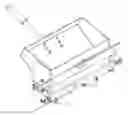
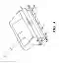
FIG. 1 shows a screed box with a standard opening.
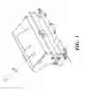
FIG. 2 shows the bottom of a screed box with a standard opening.
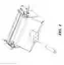
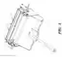
FIG. 3 shows a spacer which will provide alternate desired openings.
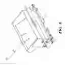
FIG. 4 shows a screed box using the spacer with a fixed opening.
FIG. 5 shows the bottom of a screed box using the spacer with a fixed opening.
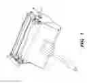
FIG. 6 shows a screed box using the spacer with a zero opening.
FIG. 7 shows the bottom of a screed box using the spacer with a zero opening.
BEST MODE FOR CARRYING OUT THE INVENTION
An adjustable spacer plate 12 mounts over the US standard screed box 10 thermoplastic die wall 22 opening 14 of 0.125″ and creates a 0.090″ opening. For Europe, the standard opening is 0.100″ and the spacer plate creates a 0.060″ opening. This eliminates the need for the user to buy another costly screed box.
Before this design a separate box was needed for screeding over stencils, but now the spacer 12 can be flipped to create a zero clearance opening. This allows the thermoplastic to come out only when an opening in the stencil pattern is present. Also, as the die 14 wears down, the spacer can be removed which lets the standard size opening be used as a substitute for the 0.090″ opening.
The spacer is attached to the box 10 using a set of acorn nuts 16. This hardware feature is beneficial in deterring thermoplastic from getting to the threads on studs 20 (alternatively, bolts or other known fasteners can be used instead of studs and acorn nuts) and allows for easier spacer plate 12 attachment and removal. As can be seen in FIG. 3, the centerline of the holes 18 is offset somewhat from the centerline of the spacer 12 to allow alternate openings.
It is contemplated that various changes and modifications may be made to the adjustable screed without departing from the spirit and scope of the invention as defined by the following claims.
Claims
1. An adjustable screed die line thickness mechanism, said screed die mechanism comprising:
a screed box having a die wall, said die wall providing an opening when said box is on the ground;
a spacer plate having a longitudinal centerline and a plurality of apertures arranged linearly along a line parallel to and offset from said centerline; and
means for removably fastening said spacer plate to said die wall in alternate positions to provide alternate opening sizes.
2. The adjustable screed die line thickness mechanism of claim 1 wherein said apertures are located so that one of said opening sizes is about zero.
Images & Drawings included:
Sources:
- United States Patent and Trademark Office - verify current appl. status at the USPTO↗
Recent applications in this class:
- » 20220290385 2022-09-15
Contrast road marking apparatus - » 20210207330 2021-07-08
Contrast road marking apparatus - » 20110020064 2011-01-27
SCREED DIE IR ABSORBTION COATING - » 20050147468 2005-07-07
Comb gate and method of use
Recent applications for this Assignee:
- » 20250101975 2025-03-27
PUMP ROD AND DRIVING LINK WITH SIDE-LOAD REDUCING CONFIGURATION - » 20240383119 2024-11-21
POWER TOOL ATTACHMENT - » 20240375133 2024-11-14
FLUID SPRAYER WITH COVERED BATTERY - » 20240316577 2024-09-26
Fluid sprayer - » 20240309595 2024-09-19
ROAD TAPING MACHINE - » 20240293832 2024-09-05
Fluid sprayer - » 20240226943 2024-07-11
Fluid sprayer with battery power - » 20240219937 2024-07-04
PAINT SPRAYER DISTRIBUTED CONTROL AND OUTPUT VOLUME MONITORING ARCHITECTURES - » 20240213720 2024-06-27
Heated hose electrical connectors - » 20240207875 2024-06-27
Mix chamber for a plural component sprayer