Driving device
US20120137803A1
2012-06-07
13/310,188
2011-12-02
✅ Patent granted
US 8,601,891 B2
2013-12-10
-
-
David M Fenstermacher
Cozen O'Connor
2032-05-29
Abstract:
A driving device having a housing tube connected to a stationary base part or a movable structural component part a protective tube connected to the other respective part a spindle drive which has a threaded spindle and a spindle nut arranged on the threaded spindle by which the housing tube and protective tube are movable axially relative to one another, and a rotary drive that drives the spindle drive via a clutch, a rotationally rigid interconnection thereof can be canceled when a determined torque is exceeded. A magnetic ring having a plurality of north and south poles is rotationally arranged near a stationary sensor element. The magnetic ring is arranged at the clutch that is connected to the threaded spindle, fixed with respect to rotation relative to it.
Inventors:
- Marian BOCHEN 24 🇩🇪 Eitelborn, Germany
- Michael Knopp 2 🇺🇸 Sterling Heights, MI, United States
- Michael KNOPP 1 🇩🇪 Koblenz, Germany
Assignee:
- Stabilus GmbH 182 🇩🇪 Koblenz, Germany
Applicant:
Interested in similar patents?
Get notified when new applications in this technology area are published.
Classification:
F16H25/2015 » CPC main
Gearings comprising primarily only cams, cam-followers and screw-and-nut mechanisms for conveying or interconverting oscillating or reciprocating motions; Screw mechanisms Means specially adapted for stopping actuators in the end position; Position sensing means
E05F15/622 » CPC further
Power-operated mechanisms for wings using electrical actuators using rotary electromotors for swinging wings operated by push-pull mechanisms using screw-and-nut mechanisms
E05Y2201/216 » CPC further
Constructional elements; Accessories therefore; Brakes; Disengaging means, e.g. clutches; Holders, e.g. locks; Stops; Accessories therefore; Disengaging means Clutches
E05Y2201/236 » CPC further
Constructional elements; Accessories therefore; Brakes; Disengaging means, e.g. clutches; Holders, e.g. locks; Stops; Accessories therefore; Actuation thereof by automatically acting means using force or torque
E05Y2201/702 » CPC further
Constructional elements; Accessories therefore; Suspension or transmission members; Accessories therefore; Suspension or transmission members elements; Screw mechanisms Spindles; Worms
E05Y2400/337 » CPC further
Electronic control; Power supply; Power or signal transmission; User interfaces; Electronic control of motors; Position control, detection or monitoring by using pulse generators of the angular type Encoder wheels
E05Y2400/342 » CPC further
Electronic control; Power supply; Power or signal transmission; User interfaces; Electronic control of motors; Position control, detection or monitoring by using pulse generators Pulse count value setting or correcting
E05Y2600/458 » CPC further
Mounting or coupling arrangements for elements provided for in this subclass; Mounting location; Visibility of the elements in or on a transmission member
E05Y2800/205 » CPC further
Details, accessories and auxiliary operations not otherwise provided for; Combinations of elements forming a unit
E05Y2800/232 » CPC further
Details, accessories and auxiliary operations not otherwise provided for; Combinations of elements of elements of different categories of motors and transmissions
E05Y2800/238 » CPC further
Details, accessories and auxiliary operations not otherwise provided for; Combinations of elements of elements of different categories of springs and transmissions
E05Y2800/40 » CPC further
Details, accessories and auxiliary operations not otherwise provided for Protection
E05Y2900/50 » CPC further
Application of doors, windows, wings or fittings thereof for vehicles
F16H25/2021 » CPC further
Gearings comprising primarily only cams, cam-followers and screw-and-nut mechanisms for conveying or interconverting oscillating or reciprocating motions; Screw mechanisms with means for avoiding overloading
Y10T74/18648 » CPC further
Machine element or mechanism; Mechanical movements; Reciprocating or oscillating to or from alternating rotary including screw and nut Carriage surrounding, guided by, and primarily supported by member other than screw [e.g., linear guide, etc.]
Y10T74/18688 » CPC further
Machine element or mechanism; Mechanical movements; Reciprocating or oscillating to or from alternating rotary including screw and nut Limit stop
Y10T74/18696 » CPC further
Machine element or mechanism; Mechanical movements; Reciprocating or oscillating to or from alternating rotary including screw and nut including means to selectively transmit power [e.g., clutch, etc.]
Y10T74/18704 » CPC further
Machine element or mechanism; Mechanical movements; Reciprocating or oscillating to or from alternating rotary including screw and nut Means to selectively lock or retard screw or nut
F16H25/12 IPC
Gearings comprising primarily only cams, cam-followers and screw-and-nut mechanisms for interconverting rotary motion and reciprocating motion with reciprocation along the axis of rotation, e.g. gearings with helical grooves and automatic reversal or cams
F16H27/02 IPC
Step-by-step mechanisms without freewheel members, e.g. Geneva drives with at least one reciprocating or oscillating transmission member
Description
BACKGROUND OF THE INVENTION
1. Field of the Invention
The invention is directed to a driving device, particularly for a hatch in a vehicle, having a housing tube connected to a stationary base part, particularly to a vehicle body, or to a movable structural component part, particularly a vehicle hatch or vehicle door, a protective tube that can be connected to the other respective part, i.e., the movable structural component part or the stationary base part, a spindle drive that has a threaded spindle and a spindle nut arranged on the threaded spindle by which the housing tube and protective tube are axially movable relative to one another, and a rotary drive that drives the spindle drive in rotation via an overload protection device formed by a clutch device, wherein the rotationally rigid interconnection thereof can be canceled when a determined torque is exceeded.
2. Description of the Related Art
There are many known variations of driving devices of the type mentioned above. However, it is disadvantageous in these drives that an erroneous calculation of the hatch position can occur in manual operation while a connected control device is inactive or when the clutch installed in the spindle drive is disengaged. Therefore, it is no longer possible for the rear hatch to move reliably to the end positions, i.e., the completely opened position or completely closed position.
SUMMARY OF THE INVENTION
Therefore, it is an object of the invention to provide a driving device of the type mentioned above having a simple and economical construction in which an accurate calculation of the hatch position is possible.
According to one embodiment of the invention a magnetic ring having a plurality of north poles and south poles is arranged to be rotationally movable near a sensor element, the magnetic ring cooperating with the sensor element is arranged at a part of the clutch device that is connected to the threaded spindle to be fixed with respect to rotation relative to it, and the sensor element is arranged so as to be stationary with respect to the housing tube.
This arrangement makes it possible to determine the position of the vehicle hatch even when the clutch device has disengaged due to overloading of the driving device.
The assembly of the structural component parts is greatly facilitated when the Hall sensor is arranged at the inner wall of a housing tube of the clutch device.
Other objects and features of the present invention will become apparent from the following detailed description considered in conjunction with the accompanying drawings. It is to be understood, however, that the drawings are designed solely for purposes of illustration and not as a definition of the limits of the invention, for which reference should be made to the appended claims. It should be further understood that the drawings are not necessarily drawn to scale and that, unless otherwise indicated, they are merely intended to conceptually illustrate the structures and procedures described herein.
BRIEF DESCRIPTION OF THE DRAWINGS
An embodiment example of the invention is shown in the drawings and described more fully in the following. The drawings show:
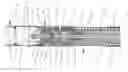
FIG. 1 is a cross section through a driving device; and
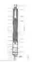
FIG. 2 is an enlarged section through the driving device according to FIG. 1.
DETAILED DESCRIPTION OF THE PRESENTLY PREFERRED EMBODIMENTS
The driving device shown in FIG. 1 has a first housing tube 1 having a first end 2 which is closed by a bottom piece 3. A threaded pin 4 is formed at the bottom piece, and a first fastening device 5 in the form of a ball socket is screwed onto this threaded pin 4. A sleeve 7 is arranged at a second end 6 opposite the first end 2, a guide bushing 8 is arranged in sleeve 7 with an interference fit. Alternatively, the sleeve 7 and guide bushing 8 are constructed to form one piece.
A rotary drive 9 comprising an electric motor 10 and a transmission 11 is arranged near the first end 2 of the first housing tube 1. A driveshaft 12 projects out of both front sides of the electric motor 10 and drives a sensor device 13 on one side and the transmission 11 on the other side. On the side of the transmission 11 opposite the electric motor 10, a transmission output shaft 14 extends in direction of the second end 6. A clutch device 15 is connected to the transmission output shaft 14 on one side and to a threaded spindle 16 of a spindle drive 17 on the other side, this threaded spindle 16 extending through the guide bushing 8. Further, a guide tube 18 which coaxially encloses the threaded spindle 16 extends through the guide bushing 8.
A spindle nut 19 which is guided in the guide tube 18 to be axially displaceable but fixed with respect to rotation relative to the guide to be is arranged on the threaded spindle 16. The spindle nut 19 is connected to one end of a spindle tube 20 which encloses the threaded spindle 16 coaxially, the threaded spindle 16 being guided in the spindle tube 20 at its end opposite the clutch device 15 by a spindle guide 21 to prevent radial movements of the threaded spindle 16. A threaded bolt 22 is arranged at the guide tube 18 at the end opposite the spindle nut 19. A supporting disk 23 which is fixed to the threaded bolt 22 by a second fastening device 24 in the form of another ball socket is in turn fitted to the guide tube 18.
A guide bushing 25 that guides the spindle tube 20 displaceably in axial direction is arranged at the end of the guide tube 18 opposite the end resting in the guide bushing 8. The guide tube 18 is coaxially enclosed by a second housing tube 26. The second housing tube 26 is supported by an inner flange 27 at the second end 6 of the first housing tube 1 and at the guide bushing 8 or sleeve 7.
The second housing tube 26 is enclosed in turn at least partially by a protective tube 28. The protective tube 28 has an inner flange 29 which contacts the supporting disk 23.
To assist the extending movement of the driving device, a helical compression spring 30 is arranged between the guide tube 18 and the second housing tube 26 and protective tube 28 and is supported at the inner flange 27 of the second housing tube 26 and the inner flange 29 of the protective tube 28.
FIG. 2 shows a section of the driving device shown in FIG. 1, particularly the individual structural component parts of the clutch device 15.
The clutch device 15 is arranged between the transmission 11 and a spindle bearing 31. The clutch device 15 comprises an inner part 32, a damping element 33, an intermediate part 34, a spring ring 35, and an outer part 36. However, different positions of the clutch device in the drivetrain and a different construction of the clutch, for example, with friction disks, are also possible.
For purposes of torque transmission, the transmission output shaft 14 is insertably connected to the inner part 32 by a positive or frictional engagement, for example, serrations. Together with the damping element 33 and the intermediate part 34, the inner part 32 forms a flexible claw coupling.
The intermediate part 34 is connected to the outer part 36 by the spring ring 35. The spring ring 35 is fixed in the outer part 36 in axial and radial direction.
The connection of the spring ring 35 to the intermediate part 34 is preferably carried out by a plurality of radially arranged spring arms that engage in radially circumferential troughs at the outer lateral surface of the intermediate part 34. These troughs are preferably wave-shaped or triangular.
Torque is transmitted into the outer part 36 of the clutch device 15 via the transmission output shaft 14, the inner part 32, the damping element 33, the intermediate part 34 and the spring ring 35.
Torque is transmitted between the spring ring 35 and the intermediate part 34 via the ends of the spring arms. Proceeding from a certain torque, the intermediate part 34 is rotated relative to the spring ring 35 and, when the intermediate part 34 rotates further, the spring arms are first pressed radially outward over the ends and then bend back again so that the ends lock into the next trough.
The clutch device 15 is supported radially and axially in the spindle bearing 31. As can be seen from FIG. 2, a connection device 37 having a smaller outer diameter is provided at the outer part, the threaded spindle 16 being inserted therein. The transmission of torque to the threaded spindle 16 takes place via a serration. The threaded spindle 16 is secured axially in the outer part 36 by a rivet connection 38. An annular disk 39 is arranged between the spindle bearing 31 and the guide tube 18 so that the clutch device 15 is fixed in axial direction. Forces acting in axial direction are guided around the clutch device by the annular disk 39 and the structural components arranged around the clutch device 15.
The end of the outer part 36 facing in the direction of the transmission 11 is beaded on the inner side so as to form a flange 40 and holds a disk 41 of a supporting element 40 in a position between the inner part 32, damping element 33, intermediate part 34 and spring ring 35 on one side and the flange 40 on the other side. A sleeve 42 which is connected to the disk 41 so as to form one piece extends onward from the disk 41 in direction of the transmission 11. A magnetic ring 43 having a plurality of north poles and south poles is arranged on the sleeve 42. The magnetic ring 43 cooperates with a sensor element 44 arranged on a printed circuit board 45. The printed circuit board 45 is arranged at the inner wall of the housing 46 of the clutch device 15.
The sensor element 44 comprises at least one Hall sensor, but preferably two Hall sensors having a defined phase offset. Although shown as one component part in the present case, it is also possible to use two separate Hall sensors.
When the movable part, for example, the hatch of a motor vehicle, is operated manually when the control device 46 is deactivated or “sleeping”, control device 46 is switched on by a signal of the Hall sensor, or of both Hall sensors, via lines, only suggested in the drawing, so that the rotational movement of the threaded spindle 16 is sensed via the outer part 36 of the clutch device 15, which outer part 36 is connected to the threaded spindle 16 so as to be fixed with respect to rotation relative to it, and by the magnetic ring 43 which is connected to the outer part 36 likewise so as to be fixed with respect to rotation relative to it.
Thus, while there have shown and described and pointed out fundamental novel features of the invention as applied to a preferred embodiment thereof, it will be understood that various omissions and substitutions and changes in the form and details of the devices illustrated, and in their operation, may be made by those skilled in the art without departing from the spirit of the invention. For example, it is expressly intended that all combinations of those elements and/or method steps which perform substantially the same function in substantially the same way to achieve the same results are within the scope of the invention. Moreover, it should be recognized that structures and/or elements and/or method steps shown and/or described in connection with any disclosed form or embodiment of the invention may be incorporated in any other disclosed or described or suggested form or embodiment as a general matter of design choice. It is the intention, therefore, to be limited only as indicated by the scope of the claims appended hereto.
Claims
What is claimed is:1. A driving device comprising:
a housing tube connectable to one of a stationary base part and a movable structural component part;
a protective tube connectable to the other of the stationary base part and the movable structural component part;
a spindle drive by which the housing tube and protective tube are movable axially relative to one another, comprising:
a threaded spindle: and
a spindle nut arranged on the threaded spindle;
a rotary drive that drives the spindle drive in rotation via an overload protection device, a rotationally rigid interconnection of the overload protection device configured to be canceled when a determined torque is exceeded;
a sensor element arranged so as to be stationary with respect to the housing tube; and
a magnetic ring having a plurality of north poles and south poles arranged to be rotationally movable near the sensor element, the magnetic ring cooperating with the sensor element,
wherein the magnetic ring is arranged at a part of the overload protection device that is connected to the threaded spindle to be fixed with respect to rotation relative to the threaded spindle.
2. The driving device according to claim 1, wherein the sensor element is arranged at the inner wall of the housing of the clutch device.
3. The driving device according to claim 1, wherein the stationary base part is a vehicle body.
4. The driving device according to claim 1, wherein the movable structural component part is one of a vehicle hatch and a vehicle door.
5. The driving device according to claim 1, wherein the overload protection device is a clutch device.
6. The driving device according to claim 1, wherein the sensor element is a Hall effect sensor.
7. The driving device according to claim 1, wherein the sensor element is a plurality of Hall effect sensors.
Images & Drawings included:

Sources:
- United States Patent and Trademark Office - verify current appl. status at the USPTO↗
Similar patent applications:
- » 20100110097
Driving device of a light source module, light source module having the driving device, driving method of the light source module, and display device having the driving device - » 20190177103
CONVEYING DRIVING DEVICE, CONVEYING DRIVING DEVICE CONTROL METHOD, AND STORAGE MEDIUM STORING CONTROL PROGRAM FOR CONVEYING DRIVING DEVICE, MOTOR DRIVE CURRENT SETTING TABLE GENERATING METHOD AND STORAGE MEDIUM STORING PROGRAM FOR GENERATING MOTOR DRIVE CURRENT SETTING TABLE, IMAGE FORMING APPARATUS, IMAGE FORMING APPARATUS CONTROL METHOD, AND STORAGE MEDIUM STORING PROGRAM FOR IMAGE FORMING APPARATUS - » 20160297456
Driving curve creation device, driving assistance device, driving control device, and driving curve creation method - » 20140213411
Driving device, electronic apparatus provided with the driving device, and driving device control method - » 20100007782
Solid-state image-capturing device, driving method thereof, camera electric charge transfer device, driving method and driving device for driving load, and electronic equipment - » 20070206423
Solid-state image-capturing device, driving method thereof, camera, electric charge transfer device, driving method and driving device for driving load, and electronic equipment - » 20100007781
Solid-state image capturing device, driving method thereof, camera, electric charge transfer device, driving method and driving device for driving load, and electronic equipment - » 20250072191
LED DRIVING DEVICE, METHOD OF FABRICATING LED DRIVING DEVICE AND DISPLAY DEVICE INCLUDING LED DRIVING DEVICE - » 20070126618
DISPLAY DEVICE DRIVE DEVICE, DISPLAY DEVICE, AND DRIVE DEVICE OR DISPLAY DEVICE CHECK METHOD - » 20060044828
Display device, driving device of display device, and driving device of light source for display device
Recent applications in this class:
- » 20250198488 2025-06-19
GUIDANCE SYSTEM - » 20250155004 2025-05-15
SELF-LOCKING DRIVE AND LINEAR ACTUATOR - » 20250155003 2025-05-15
SELF-LOCKING DRIVE AND LINEAR ACTUATOR - » 20250137514 2025-05-01
INTELLIGENT DEVICE FOR DETERMINING OPERATION POINT AND SCREW ROD THEREOF - » 20250084915 2025-03-13
MOTORIZED SYSTEM - » 20250012346 2025-01-09
Electromechanical Cylinder - » 20240352994 2024-10-24
METHOD FOR PRODUCING VARIOUS VARIANTS OF A SERIES OF AN ELECTRICALLY OPERABLE ACTUATION SYSTEM, FULLY ELECTRICALLY OPERABLE OR HYBRID-OPERABLE DRIVE TRAIN OF A MOTOR VEHICLE, AND CONFIGURATION SYSTEM FOR PRODUCING VARIOUS VARIANTS OF A SERIES OF AN ELECTRICALLY OPERABLE ACTUATION SYSTEM - » 20240218918 2024-07-04
Torsionally compliant actuator end stop - » 20240068550 2024-02-29
Self-locking drive and linear actuator - » 20240011544 2024-01-11
Electromechanical linear actuator with hollow shaft motor
Recent applications for this Assignee:
- » 20250236225 2025-07-24
KINETIC SEAT ASSEMBLIES HAVING DAMPERS FOR FIXED COMPONENTS AND MOVABLE COMPONENTS INCLUDING LATERAL DAMPING MECHANISMS AND FLUID RESERVOIRS - » 20250012337 2025-01-09
DAMPING APPARATUS - » 20240344379 2024-10-17
LINEAR DRIVE FOR A CLOSURE ELEMENT OF A MOTOR VEHICLE - » 20240328232 2024-10-03
ACTUATOR FOR THE ROTARY DRIVE OF A VEHICLE FLAP - » 20240271475 2024-08-15
ELECTRIC SIDE DOOR DRIVE ASSEMBLY FOR A VEHICLE - » 20240167545 2024-05-23
ACTUATING DEVICE - » 20240102331 2024-03-28
Drive system for opening and closing a motor-vehicle door, and motor vehicle having the drive system - » 20240093435 2024-03-21
System, method and support element for actively damping acoustic vibrations of a rail for rail traffic - » 20240084827 2024-03-14
PISTON ASSEMBLIES AND METHODS OF USING SAME - » 20240026199 2024-01-25
Gas pressure spring comprising an expanding wax, drive system comprising the gas pressure spring