Plastic Filters of Irrigation Systems
US20120138521A1
2012-06-07
13/125,974
2010-06-09
Abstract:
Invention is about improvements that are made in water redirecting, disk cleaning systems and sealing of filters which are used in irrigation systems for filtering contaminants at solid state in the water. Water leakage is prevented by separate usage of seal and o-ring as sealing between body and container. Another problem is solved by design of fixed stream director apparatus. To prevent disc moving from their axis during screw releasing of upper cap, a cap was designed and easy disc cleaning attained by same dimension of inner diameters of movable cap and disc holder.
Interested in similar patents?
Get notified when new applications in this technology area are published.
Classification:
B01D29/46 » CPC main
Other filters with filtering elements stationary during filtration, e.g. pressure or suction filters, or filtering elements therefor; Edge filtering elements, i.e. using contiguous impervious surfaces of flat, stacked bodies
B01D29/70 » CPC further
Other filters with filtering elements stationary during filtration, e.g. pressure or suction filters, or filtering elements therefor; Regenerating the filter material in the filter by forces created by movement of the filter element
B01D29/908 » CPC further
Other filters with filtering elements stationary during filtration, e.g. pressure or suction filters, or filtering elements therefor having feed or discharge devices for feeding provoking a tangential stream
B01D35/02 IPC
Other filtering devices; Auxiliary devices for filtration; Filter housing constructions Filters adapted for location in special places, e.g. pipe-lines, pumps, stop-cocks
C02F1/00 IPC
Treatment of water, waste water, or sewage
Description
TECHNICAL AREA
Invention is about improvements that are made in water redirecting, disk cleaning systems and sealing of filters which are used in irrigation systems for filtering contaminants at solid state in the water.
PRIOR ART
Water leads the most important needs which are necessary for life. Using limited water sources with the most efficient way has been becoming more and more important. Forasmuch as insufficient irrigation is performed, it is hard to obtain efficiency at many areas of agriculture. Water should be delivered without any loss to the target, in order to achieve optimum efficiency. This fact improves value of sealing elements. One sealing is used between filter body and vessel, which in the end resulted with water leakage. Desired pressure can't be reached at irrigation systems because of insufficient sealing of one seal against pressure, so expected irrigation couldn't be fulfilled and desired efficiency couldn't be attained. Also water, work power and energy losses are added to account of country.
Another problem that is faced is cleaning disks during operation to make contaminants (foreign matters) fall (sediment, settle) downwards in order to observe filters main work which is cleaning solid contaminants. This duty is performed by stream director apparatus. Stream director apparatus in filters that are manufactured by known practice, starts to rotate by the pressure that water drives and can't perform its spiral directing job, because that it is not fixed. Direct water transition through filter causes rapid filling of discs and in consequence, it makes them work insufficiently. This situation requires operator action. If operator doesn't act, pressure would decrease and transferred water amount would degrade. This means insufficient irrigation. Filter cleaning is done as operator opens upper cap after releases its screw and moves discs towards upwards and downwards. In the known technique, discs make operator job harder by moving from their axis due to thin screw belly (body) of upper cap, comparing to disc holder inner diameter. It becomes harder when above disadvantage added to hard cleaning conditions and this prevents proper and sufficient execution of procedure. Also time and work power losses must not be forgot.
BRIEF DESCRIPTION OF INVENTION
In the filter that is developed at the end of studies of our experts by initiating with disadvantages of known technique, water leakage is prevented by separate usage of seal and o-ring as sealing between body and container. Another problem is solved by design of fixed stream director apparatus. To prevent disc moving from their axis during screw releasing of upper cap, a cap was designed and easy disc cleaning attained by same dimension of inner diameters of movable cap and disc holder.
MEANING OF FIGURES
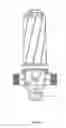
FIG. 1. Assembled view
FIG. 2. Disassembled view
FIG. 3. Spiral mixer (twister)
FIG. 4. Cap
FIG. 5. Container
FIG. 6. Disc holder
FIG. 7. Body
FIG. 8. Screw
FIG. 9. Nut
Meanings of part numbers which are provided at figures are given below.
1. Container
2. Screw
-
- 2.1. Segment
3. Cap
4. Disc holder
5. Disc
6. Twister
7. Body
-
- 7.1. O-ring
- 7.2. Seal
8. Nut
DETAILED DESCRIPTION OF INVENTION
Invention is consist of Container (1), Screw (2) which contains Segment (2.1), Cap (3), Disc holder (4), Disc (5), Twister (6), Nut (8) and Body (7) which contains O-ring (7.1) and Seal (7.2). Starting filter assembly is initiated with nut (8) mounting after mounting seal (7.2) and o-ring (7.1) to sealing channels of the body. After that, twister (6) mounted to disc holder (4) and discs (6) which have filtering contaminant solid substances during their filter transition, are aligned (lined up) on disc holder (4). Cap (3) mounted and screwed (2) after disk (5) aligning job completed. Filter becomes ready when container (1) and body (7) are fitted. A phased sealing system is placed between container (1) and body (7), channels that o-ring (7.1) and seal (7.2) can be used together is made and seal (7.2) and o-ring (7.1) are placed to these channels separately so probable water leakages are avoided. After water enters filter, it faces twister (6) which is mounted to disc holder (4) that is placed just over the water entry. Twister (6) sends water to discs (5) as spiral stream. While discs (5) hold foreign substances, water makes those substances to fall downwards by its spiral movement. At filter cleaning, cap (3) that mounted onto disc holder (4), slides to upwards by released screw (2) and discs (5) move easily without horizontal movement. Operator cleans easily and rapidly and make filter ready to re-operate.
Claims
What is claimed is:1. A plastic filter for an irrigation system comprising: a plastic container with a space to place a rubber O-ring in the plastic container; a plastic screw with plastic segment thereof; a plastic cap; a plastic disc holder; a plastic twister attached to the plastic disc holder; a rubber seal; and a plastic body wherein the rubber seal is attached to.
2. The plastic filter as described in claim 1 wherein said plastic cap has three standing supports.
3. The plastic filter as described in claim 1 wherein the plastic twister has plurality of grooves in it.
4. The plastic filter as described in claim 3 wherein the plastic twister has three grooves in it.
5. The plastic filter as described in claim 3 wherein the plastic twister is attached to the plastic disc holder via one of the three grooves of the plastic twister to prevent rotating of plastic twister to the left and to the right during water flow and to gain helical flow of water.
6. The plastic filter as described in claim 1 wherein the plastic cap extends to the length of the plastic disc holder by loosening of the plastic screw and exists on the plastic disc holder with the same size of the plastic disc holder.
7. The plastic filter as described in claim 1 wherein the plastic screw comprises a plastic segment thereof to prevent a plastic disc from falling between the plastic screw and the plastic disc holder during cleaning of solid particles on the plastic disc.
8. The plastic filter as described in claim 1 wherein the rubber o-ring is placed on the plastic container.
9. The plastic container as described in claim 8 further comprising a space to place O-ring to provide sealing between the plastic body and the plastic container.
Images & Drawings included:


Sources:
- United States Patent and Trademark Office - verify current appl. status at the USPTO↗
Recent applications in this class:
- » 20250050250 2025-02-13
WATER PURIFICATION SYSTEM AND METHOD - » 20230102465 2023-03-30
RECIPROCATING LAMINATION SPIRAL SOLID-LIQUID SEPARATOR - » 20220203272 2022-06-30
Tangential flow filtration module and tangential flow filtration assembly - » 20220062801 2022-03-03
SEPARATING DEVICE AND USE OF A SEPARATING DEVICE - » 20210220762 2021-07-22
Self cleaning disc filter apparatus - » 20200122063 2020-04-23
Filter panel with macro, micro and nano structures - » 20200078712 2020-03-12
Filter element and filter module comprising same - » 20180345180 2018-12-06
Boundary layer modification in closely-spaced passages - » 20180161705 2018-06-14
STACKED-PLATE FILTER AND A METHOD OF USE - » 20180093210 2018-04-05
DISK FILTER AND METHOD FOR THE MANUFACTURE THEREOF