Rail attachment structure of electric device
US20120138759A1
2012-06-07
13/322,018
2010-06-14
✅ Patent granted
US 8,651,442 B2
2014-02-18
WO; PCT/JP2010/003937; 20100614
WO; WO2011/021335; 20110224
Daniel J Troy | Muhammad Ijaz
Manubu Kanesaka
2030-06-14
Abstract:
First fitting portions (9a and 9b) and second fitting portions (9c and 9d) are arranged in a hook shape on the bottom (3a) of a housing to face each other. The first fitting portions are fittingly engaged to one rail edge (2a) of a rail (2) in the width direction and the second fitting portions are fittingly engaged to the other rail edge (2b) of the rail. A linear spring (10) bent in a mountain shape is disposed on the bottom of the housing. The linear spring elastically deforms to reduce the inclination angle of the mountain by contacting the end surface of the one rail edge engaged to the first fitting portions. The urging force of the linear spring urges the rail such that the other rail edge is pressed by the second fitting portions.
Inventors:
- Kouetsu Takaya 53 🇯🇵 Kounosu-shi, Japan
- Koji Okubo 5 🇯🇵 Kounosu-shi,, Japan
- Yasuhiro Naka 41 🇯🇵 Kounosu-shi,, Japan
- Kenji Suzuki 31 🇯🇵 Kounosu-shi, Japan
- Kouetsu Takaya 58 🇯🇵 Kounosu, Japan
- Koji Okubo 10 🇯🇵 Kounosu, Japan
- Yasuhiro Naka 47 🇯🇵 Kounosu, Japan
- Kenji Suzuki 36 🇯🇵 Kounosu, Japan
Assignee:
- FUJI ELECTRIC FA COMPONENTS & SYSTEMS CO., LTD. 11 🇯🇵 Chuo-ku, Tokyo, Japan
- FUJI ELECTRIC FA COMPONENTS & SYSTEMS CO., LTD. 109 🇯🇵 Tokyo, Japan
Applicant:
Interested in similar patents?
Get notified when new applications in this technology area are published.
Classification:
E04G3/00 IPC
Scaffolds essentially supported by building constructions, e.g. adjustable in height
H02B1/052 » CPC main
Frameworks, boards, panels, desks, casings; Details of substations or switching arrangements; Boards, panels, desks; Parts thereof or accessories therefor; Mounting thereon of switches or of other devices in general, the switch or device having, or being without, casing Mounting on rails
H05K7/14 IPC
Constructional details common to different types of electric apparatus Mounting supporting structure in casing or on frame or rack
H05K7/14 IPC
Constructional details common to different types of electric apparatus Mounting supporting structure in casing or on frame or rack
A47B96/00 IPC
Details of cabinets, racks or shelf units not covered by a single one of groups - ; General details of furniture
A47K1/00 IPC
Wash-stands; Appurtenances therefor
A47K5/00 IPC
Holders or dispensers for soap, toothpaste, or the like
F16L3/08 IPC
Supports for pipes, cables or protective tubing, e.g. hangers, holders, clamps, cleats, clips, brackets substantially surrounding the pipe, cable or protective tubing
F21V21/00 IPC
Supporting, suspending, or attaching arrangements for lighting devices ; Hand grips
F21V35/00 IPC
Candle holders
A47B96/06 IPC
Details of cabinets, racks or shelf units not covered by a single one of groups - ; General details of furniture Brackets or similar supporting means for cabinets, racks or shelves
F16B1/00 IPC
Devices for securing together, or preventing relative movement between, constructional elements or machine parts
G09F7/18 IPC
Signs, name or number plates, letters, numerals, or symbols ; Panels or boards Means for attaching signs, plates, panels, or boards to a supporting structure
A47G29/00 IPC
Supports, holders, or containers for household use, not provided for in groups - or
F16M11/00 IPC
Stands or trestles as supports for apparatus or articles placed thereon Stands for scientific apparatus such as gravitational force meters
H01R13/60 IPC
Details of coupling devices of the kinds covered by groups or - Means for supporting coupling part when not engaged
H01R13/66 IPC
Details of coupling devices of the kinds covered by groups or - Structural association with built-in electrical component
Description
TECHNICAL FIELD
The present invention relates to a rail attachment structure of an electric device for attaching an electric device, such as a wiring circuit breaker and an electromagnetic contactor, to a rail provided in, for example, a distributing board.
BACKGROUND ART
In order to attach an electric device to a rail, a structure has been proposed in which a fixing claw is integrally formed on one side of the bottom of a housing of the electric device, a movable claw removably engaged to the side surface of the housing is provided at a position facing the fixing claw of the bottom of the housing, wherein the fixing claw is engaged to one edge of the rail, and the movable claw is engaged to the other edge of the rail, thereby attaching the electric device to the rail (for example, Patent Document 1).
Citation List
Patent Document
Patent Document 1: Japanese Patent Application Laid-Open (JP-A) No. 62-188035
DISCLOSURE OF INVENTION
Problems to be Solved By the Invention
However, the attachment structure according to the related art has the following problems in terms of manufacturing costs.
That is, since the movable claw is provided on the side surface of the housing, the number of components increases, the structure becomes complicated, and the number of assembly processes including a manual process of assembling the movable claw increases, which results in an increase in manufacturing costs.
In addition, when the electric device is detached from the rail, a tool is needed to remove the movable claw, and thus, the handling of the movable claw is problematic.
The invention has been made in view of the above-mentioned problems and an object of the invention is to provide a rail attachment structure of an electric device capable of simply attaching an electric device to a rail with a small number of components and a small number of assembly processes and detaching the electric device from the rail without using a tool.
Means for Solving the Problems
In order to achieve the object, the present embodiment provides a rail attachment structure of an electric device for attaching an electric device to a rail. The rail attachment structure of an electric device includes: first and second fitting portions arranged in a hook shape on the bottom of a housing of the electric device and facing each other, the first fitting portion fittingly engaged to one rail edge of the rail in a width direction and the second fitting portion fittingly engaged to the other rail edge of the rail in the width direction; and a linear spring bent in a mountain shape disposed on the bottom of the housing. The linear spring elastically deforms to reduce the inclination angle of the mountain shape by contacting an end surface of the one rail edge engaged to the first fitting portion. The urging force of the linear spring urges the rail such that the other rail edge is pressed by the second fitting portion.
According to the rail attachment structure of the electric device of the embodiment, it is possible to attach or detach an electric device to a rail only by elastically deforming the mountain-shape linear spring to fit and remove the first fitting portion and the second fitting portion.
The rail attachment structure of an electric device according to the above-mentioned embodiment may further include a spring locking portion that is provided on the bottom of the housing and locks a top portion of the mountain-shape linear spring.
According to the rail attachment structure of the electric device of the embodiment, it is possible to elastically deform the linear spring with ease such that the inclination angle of the mountain is reduced.
The rail attachment structure of an electric device according to the above-mentioned embodiment may further include a horizontal deviation preventing portion disposed on the bottom of the housing. A locked portion bent in a concave shape may be arranged on the top portion of the mountain-shape of the linear spring, and the horizontal deviation preventing portion may contact the inside of the locked portion.
According to the rail attachment structure of the electric device of the embodiment, even when external force is applied in the longitudinal direction of the linear spring, the linear spring horizontal deviation preventing portion reliably restricts the movement of the linear spring.
In the rail attachment structure of an electric device according to the above-mentioned embodiment, a pair of the first fitting portions may be separately provided so as to be fittingly engaged to two points of the one rail edge, and the linear spring may be arranged between the pair of first fitting portions such that it can be elastically deformed.
According to the rail attachment structure of the electric device of the embodiment, it is possible to ensure a sufficient space when the linear spring is elastically deformed.
Effects of the Invention
According to the rail attachment structure of the electric device according to the invention, it is possible to attach and detach an electric device to and from a rail only by elastically deforming the mountain-shape linear spring thereby to fit and remove the first fitting portion and the second fitting portion. Therefore, it is possible to simply attach an electromagnetic contactor to a rail with a small number of components and a small number of assembly processes and detach the electromagnetic contractor from the rail without using a tool.
BRIEF DESCRIPTION OF DRAWINGS
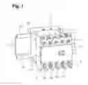
FIG. 1 is a perspective view illustrating an electromagnetic contactor as an electric device attached to a rail.
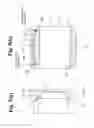
FIG. 2 is a diagram illustrating a linear spring mounted to the bottom of the electromagnetic contactor.
FIG. 3 is a diagram illustrating an initial operation of attaching the electromagnetic contactor to the rail.
FIG. 4 is a diagram illustrating the middle of the operation of attaching the electromagnetic contactor to the rail.
FIG. 5 is a diagram illustrating the completion of the operation of attaching the electromagnetic contactor to the rail.
BEST MODE FOR CARRYING OUT THE INVENTION
Hereinafter, exemplary embodiments (hereinafter, referred to as embodiments) of the invention will be described in detail with reference to the accompanying drawings.
FIG. 1 is a diagram illustrating an electromagnetic contactor 1 attached to a rail 2 provided on, for example, a distributing board. The rail 2 includes a pair of upper and lower fitting edges 2a and 2b. The edges 2a and 2b extend in parallel to each other. The electromagnetic contactor 1 is engaged to the edges 2a and 2b.
The electromagnetic contactor 1 includes a lower case 3 and an upper case 4 which are made of an insulating synthetic resin material. The upper case 4 includes terminal portions 5a to 5d each having a contact point and a coil terminal 6 of an electromagnet. An arc-extinguishing cover 7 and a terminal cover 8 covering the terminal portions 5a to 5d each having a contact point and the coil terminal 6 of the electromagnet are mounted on the upper case 4.
As shown in FIG. 2, first fitting portions 9a and 9b, second fitting portions 9c and 9d, a linear spring 10, and a spring holding portion 11 are provided on the bottom 3a of the lower case 3 of the electromagnetic contactor 1.
That is, the first fitting portions 9a and 9b are formed at the upper left and right ends of the bottom 3a, and the second fitting portions 9c and 9d are formed at the lower left and right ends of the bottom 3a. The first fitting portions 9a and 9b are formed in a hook shape toward the lower end of the bottom 3a so as to have a gap which the upper fitting edge 2a of the rail 2 is inserted. The second fitting portions 9c and 9d are formed in a hook shape toward the upper end of the bottom 3a so as to have a gap which the lower fitting edge 2b of the rail 2 is inserted.
The linear spring 10 is formed by bending an elastic linear member having a diameter of 0.5 mmφ to 1.5 mmφ in a mountain shape. As shown in FIG. 2, the linear spring 10 includes a pair of pressing spring portions 10a and 10b extending linearly toward the center in the longitudinal direction while being inclined at the same angle as each other, and a locked portion 10c connected to the pair of pressing spring portions 10a and 10b at the center in the longitudinal direction and bent in a semicircular shape. Both ends of the linear spring 10, which is end portions 10a1 and 10b1 of the pair of pressing spring portions 10a and 10b, are disposed inside the first fitting portions 9a and 9b. Even when the pair of pressing spring portions 10a and 10b is elastically deformed such that the upward inclination thereof is reduced, the end portions 10a1 and 10b1 do not contact the first fitting portions 9a and 9b.
The spring holding portion 11 includes a pair of linear spring sandwiching portions 12a and 12b, a linear spring holding boss 13, and a linear spring horizontal deviation preventing portion 14.
The pair of linear spring sandwiching portions 12a and 12b protrudes in a visor shape from the upper wall portion between the first fitting portions 9a and 9b to the lower end of the bottom 3a. The pair of pressing spring portions 10a and 10b close to the locked portion 10c of the linear spring 10 is interposed and held between the pair of linear spring sandwiching portions 12a and 12b.
The linear spring holding boss 13 is formed so as to protrude from the bottom 3a between the pair of linear spring sandwiching portions 12a and 12b and is engaged to the locked portion 10c of the linear spring 10 from the outside.
The linear spring horizontal deviation preventing portion 14 is a member that protrudes from the upper wall portion between the pair of linear spring sandwiching portions 12a and 12b in a direction perpendicular to the bottom 3a and contact the inside of the locked portion 10c of the linear spring 10 interposed between the pair of linear spring sandwiching portions 12a and 12b.
One rail edge according to the invention corresponds to the upper fitting edge 2a, the other rail edge according to the invention corresponds to the lower fitting edge 2b, a housing according to the invention corresponds to the lower case 3, the bottom of the housing according to the invention corresponds to the bottom 3a, and a spring locking portion according to the invention corresponds to the linear spring sandwiching portions 12a and 12b.
The linear spring 10 according to this embodiment is assembled to the spring holding portion 11 as follows. As shown in FIG. 2, when the linear spring 10 slides to the spring holding portion 11 in the direction of an arrow, the locked portion 10c passes through the linear spring holding boss 13 and the pair of pressing spring portions 10a and 10b close to the locked portion 10c is interposed and held between the pair of linear spring sandwiching portions 12a and 12b. Then, the pair of pressing spring portions 10a and 10b is arranged along the bottom 3a between the first fitting portions 9a and 9b while being bent a little. In this way, the assembly of the linear spring 10 is completed.
Since the linear spring holding boss 13 is engaged to the locked portion 10c of the linear spring 10 from the outside, the falling-off of the linear spring 10 from the pair of linear spring sandwiching portions 12a and 12b is reliably prevented.
In addition, even when external force is applied in the longitudinal direction of the linear spring 10, the movement of the linear spring 10 in the longitudinal direction is restricted since the linear spring horizontal deviation preventing portion 14 contacts the inside of the locked portion 10c of the linear spring 10.
Next, a process of mounting the electromagnetic contactor 1 according to this embodiment to the rail 2 will be described with reference to FIGS. 3 to 5. First, as shown in FIG. 3, the first fitting portions 9a and 9b are hooked to the upper fitting edge 2a of the rail 2, and a load is applied downward to the electromagnetic contactor to elastically deform the linear spring 10 such that the upward inclination (the inclination angle of the maintain) of the pair of pressing spring portions 10a and 10b contacts the upper fitting edge 2a is reduced. Then, the third fitting protrusions 9c and 9d are pressed against the lower side of the lower fitting edge 2b of the rail 2.
Then, the application of the load to the electromagnetic contactor 1 is released. In this way, as shown in FIG. 4, the urging force of the pair of pressing spring portions 10a and 10b starts applying to the upper fitting edge 2a of the rail 2, and as a result, the electromagnetic contactor 1 gradually moves up. Then, the lower fitting edge 2b of the rail 2 is inserted into the second fitting portions 9c and 9d, as represented by an arrow.
Then, as shown in FIG. 5, in the electromagnetic contactor 1, the first fitting portions 9a and 9b are fitted to the upper fitting edge 2a of the rail 2 and the second fitting portions 9c and 9d are fitted to the lower fitting edge 2b of the rail 2.
The urging force of the pair of pressing spring portions 10a and 10b of the linear spring 10 is applied to the upper fitting edge 2a of the rail 2, and the second fitting portions 9c and 9d press the end surface of the lower fitting edge 2b of the rail 2. In this way, the electromagnetic contactor 1 is mounted to the rail 2.
A tool is unnecessary to detach the electromagnetic contactor 1 from the rail 2. It is possible to detach the electromagnetic contactor 1 from the rail 2 by applying a load downward to the electromagnetic contactor 1 to elastically deform the pair of pressing spring portions 10a and 10b of the linear spring 10 such that the upward inclination thereof is reduced, moving the electromagnetic contactor 1 down, removing the second fitting portions 9c and 9d from the lower fitting edge 2b of the rail 2, and removing the upper fitting edge 2a from the first fitting portion 9a and 9b of the rail 2.
Next, the operation and effect of this embodiment will be described.
According to this embodiment, it is possible to attach and detach the electromagnetic contactor 1 to and from the rail 2 only by arranging the linear spring 10, which is bent in a mountain shape, on the bottom 3a of the lower case 3 and elastically deforming the linear spring 10 to fit or remove the first fitting portions 9a and 9b and the second fitting portions 9c and 9d. Therefore, it is possible to simply attach the electromagnetic contactor 1 with a small number of components and a small number of assembly processes, and detach the electromagnetic contactor 1 from the rail 2 without using a tool.
In the linear spring 10, since the pair of pressing spring portions 10a and 10b close to the locked portion 10c is interposed between the pair of linear spring sandwiching portions 12a and 12b, the pair of pressing spring portions 10a and 10b can be elastically deformed with ease such that the upward inclination (the inclination angle of the mountain) thereof is reduced. Even when external force is applied in the longitudinal direction of the linear spring 10, it is possible to reliably restrict the movement of the linear spring 10 in the longitudinal direction since the linear spring horizontal deviation preventing portion 14 contacts the inside of the locked portion 10c of the linear spring 10.
In addition, both ends (end portions 10a1 and 10b1) of the linear spring 10 are disposed inside the first fitting portions 9a and 9b. Even when the pair of pressing spring portions 10a and 10b is elastically deformed such that the upward inclination thereof is reduced, it is possible to ensure a sufficient space during the deformation of the linear spring 10 since the end portions 10a1 and 10b1 do not contact the first fitting portions 9a and 9b.
INDUSTRIAL APPLICABILITY
As described above, the rail attachment structure of the electric device according to the invention is useful to simply attach an electric device to a rail with a small number of components and a small number of assembly processes.
EXPLANATION OF REFERENCE NUMERALS AND SIGNS
1: electromagnetic contactor
2: rail
2a: upper fitting edge
2b: lower fitting edge
3: lower case
3a: bottom
4: upper case
5a˜5d: terminal portion
6: coil terminal
7: arc-extinguishing cover
8: terminal cover
9a, 9b: first fitting portion
9c, 9d: second fitting portion
10: linear spring
10a, 10b: pressing spring portion
10a1, 10b1: end portion of pressing spring portion
10c: locked portion
11: spring holding portion
12a, 12b: linear spring sandwiching portion
13: linear spring holding boss
14: horizontal deviation preventing portion
Claims
1. A rail attachment structure of an electric device for attaching an electric device to a rail, comprising:
first and second fitting portions arranged in a hook shape on a bottom of a housing of the electric device and facing each other, the first fitting portion fittingly engaging one rail edge of the rail in a width direction and the second fitting portion fittingly engaging another rail edge of the rail in the width direction; and
a linear spring bent in a mountain shape disposed on the bottom of the housing,
wherein the linear spring elastically deforms to reduce an inclination angle of the mountain shape by contacting an end surface of the one rail edge engaged to the first fitting portion; and
an urging force of the linear spring is applied to the rail such that the other rail edge is pressed by the second fitting portion.
2. A rail attachment structure of an electric device according to claim 1, further comprising a spring locking portion disposed on a bottom of the housing and locking a top portion side of the mountain-shape linear spring.
3. The rail attachment structure of an electric device according to claim 1, wherein the linear spring further includes a locked portion bent in a concave shape and arranged on a top portion of the mountain-shape linear spring; and
a horizontal deviation preventing portion disposed on a bottom of the housing contacts an inside of the locked portion.
4. A rail attachment structure of an electric device according to claim 1, wherein a pair of the first fitting portions is separately provided so as to be fittingly engaged to two points of the one rail edge, and the linear spring is elastically deformably arranged between the pair of first fitting portions.
Images & Drawings included:


Sources:
- United States Patent and Trademark Office - verify current appl. status at the USPTO↗
Recent applications in this class:
- » 20250293486 2025-09-18
PLATE FOR DIN RAIL STYLE DEVICES - » 20250038491 2025-01-30
Power Distribution Unit with DIN-Rail Breaker Panel Mount - » 20250038490 2025-01-30
DIN RAIL UNIT FOR MOUNTING ELECTRONIC DEVICES THEREON - » 20240204490 2024-06-20
Switchgear Current Transformer Replacement System - » 20240079858 2024-03-07
A COMPACT CONTACTOR MODULE FOR INSTALLATION IN A POWER POST - » 20230238783 2023-07-27
Arrangement with a support rail and housings strung together thereon - » 20230216281 2023-07-06
CONVERTER, METHOD OF INSTALLING A POWER SYSTEM, AND USE OF A CONVERTER - » 20230033407 2023-02-02
Arrangement of a busbar adapter with one or more electro-mechanical switching devices - » 20220077664 2022-03-10
Switching and/or distributing device - » 20210376576 2021-12-02
Retractable DIN clip
Recent applications for this Assignee:
- » 20220122790 2022-04-21
Electromagnetic contactor - » 20220084766 2022-03-17
Electric device with a main body frame including a snap-fit mechanism - » 20180218862 2018-08-02
Operation coil drive device of electromagnetic contactor - » 20180197707 2018-07-12
Electromagnetic contactor - » 20180174786 2018-06-21
Operation coil drive device for magnetic contactor - » 20180158635 2018-06-07
Electromagnetic contactor - » 20180158634 2018-06-07
Electromagnetic contactor - » 20170358413 2017-12-14
Contact device and electromagnetic contactor using same - » 20170213672 2017-07-27
Switch device - » 20160365211 2016-12-15
Electromagnetic contactor