INSOLE FOR SHOES
US20120151794A1
2012-06-21
13/392,480
2010-08-25
Abstract:
An insole is proposed for a shoe. The insole has a flat back side in direction of the shoe outsole and a dome-shaped structure on the front side. The dome-shaped structure has a base surface of a maximum of 25% of the insole surface; the dome-shaped structure is positioned under the cuboid bone of the shoe wearer. A longitudinal axis can be associated with the dome-shaped structure at its apex, wherein the longitudinal axis of the dome-shaped structure encloses an angle (φ) in a range from 5° to 75° with the longitudinal axis of the insole.
Interested in similar patents?
Get notified when new applications in this technology area are published.
Classification:
A43B7/223 » CPC main
Footwear with health or hygienic arrangements with foot-supporting parts with fixed flat-foot insertions, metatarsal supports, ankle flaps or the like characterised by the constructive form
A43B7/143 » CPC further
Footwear with health or hygienic arrangements with foot-supporting parts with pads or holes on one or more locations, or having an anatomical or curved form characterised by the location under the foot situated under the lateral arch, i.e. the cuboid bone
A61F5/14 » CPC further
Orthopaedic methods or devices for non-surgical treatment of bones or joints ; Nursing devices; Anti-rape devices; Orthopaedic devices, e.g. splints, casts or braces Special medical insertions for shoes for flat-feet, club-feet or the like
A43B13/38 IPC
Soles; Sole-and-heel integral units Built-in insoles joined to uppers during the manufacturing process, e.g. structural insoles; Insoles glued to shoes during the manufacturing process
Description
CROSS REFERENCE TO RELATED APPLICATION
This is a U.S. national stage of application No. PCT/EP2010/062410, filed on Aug. 25, 2010. Priority is claimed on Europe, Application No. 09168688.1 filed Aug. 26, 2009 the contents of which are incorporated here by reference.
BACKGROUND OF THE INVENTION
The invention is directed to an insole for shoes, which has a flat back side in direction of the shoe outsole with which the proposed insole is brought into contact and a dome-shaped structure on the front side.
To allow a comprehensive appraisal of the present invention, the closed movement cycle of a walking human will first be considered analytically. This closed movement cycle involves not only the foot but also the entire lower extremity. For this purpose, the foot must contact the ground. When the foot contacts the ground, each movement of parts of this foot affects all of the other parts of the corresponding leg.
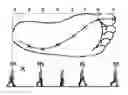
The walking movement of each leg is divided into the stance phase and the swing phase. The stance phase is further differentiated into three component phases; see FIG. 1 which illustrates the human gait using the example of the right leg.
-
- The contact phase, the first component phase of the stance phase, begins by the foot striking the ground with the outer edge of the heel. The tibia rotates internally and the inner side of the foot is raised slightly. In this phase, the foot rolls further inward until the metatarsus supports the full weight. The tibia rotates externally and the ankle pronates (rolls inward) by up to 8° so that the foot prepares for the propulsive phase. In short, the foot has absorbed the shock of contact with the ground, adapted to the uneven surface, and flattened out. The contact phase is concluded when the forefoot is in full contact with the ground. The primary function of this phase is to absorb the shock when striking the ground and adapt to different ground surfaces (adaptation).
- The second component phase of the stance phase, the midstance phase, begins with the forefoot fully contacting the ground and ends with the heel lifting off from the ground. Body weight travels over the foot when the tibia and the rest of the body move forward. The primary function of the foot in this phase is to store, with as little loss as possible, the energy gained during the first component phase and reserve it for the propulsive phase, comparable to a bouncing rubber ball.
- The third component phase of the stance phase, the propulsive phase, begins with the lifting of the heel; the muscles, ligaments and tendons are flexed. The forefoot and hindfoot together form a springboard by which the toes lift the weight of the body (forward) off the ground. The body is propelled forward during this component phase, and the weight is shifted to the other foot when this other foot makes contact with the ground. This phase has a duration of approximately 2 seconds and takes up 33% of the entire stance phase.
- At the start of this third component phase of the stance phase, the subtalar joint supinates (rolls outward) and ensures that the center of pressure remains under the outer side of the forefoot, which ensures that the cuboid bone locks with the navicular bone. The foot transforms from mobile adaptor to rigid lever in order to propel the body forward during this phase. The cuboid is exceptional in that it is the only bone in the foot that articulates with both the metatarsal joint (tarsometatarsal articulation or Lisfranc joint) and the tarsal joint (midtarsal or Chopart's joint); further, it is the only bone that links the lateral column with the transverse foot arch. Consequently, the cuboid is the keystone of the rigid, static lateral column and thus imparts its own stability to the foot.
- Locking of the cuboid with respect to the navicular provides for a very strong support through the participating ligaments and, in so doing, spares the muscles which would otherwise be severely tasked, since the vertical forces at this moment can exceed 125% of the body weight. Towards the end of the propulsive phase, unlocking of the cuboid is required after the locking has taken place at the start of the propulsive phase. A co-contraction of the fibularis longis (also known as peroneus muscle) and tibialis anterior takes place, which leads to counter-contractions and brings about a transverse pulling and supporting effect which substantially aligns the bones of the midtarsal region. The supporting effect of the tendons of the peroneus longus muscle around the cuboid is essential for control of the function of the transverse arch for stability and adaptability. To reach the end of the propulsive phase in which the big toe leaves the ground, the foot must now rotate internally, otherwise known as pronation. If the cuboid were not released or were unlocked, each joint would lose a small portion of its movement and, therefore, also a small portion of its forces needed for toe-off: this would lead to inhibition of muscular force, endurance, balance and proprioception. Moreover, there would be a tendency for lateral sprains because this structure is basically a raising structure (supination) and the person could not achieve a functional lowering (pronation). In such a case, the natural flow of force through the foot illustrated in FIG. 2 would be interrupted or limited. Before the big toe leaves the ground, there occurs a dorsiflexion of the big toe together with the four small toes of the same foot and a plantarflexion of the first metatarsal bone together with the other metatarsal bones of the same foot. The dorsiflexion of the big toe is known as the windlass effect and is made possible because of the contraction of the extensor hallicus longus muscle. With the dorsiflexion of the big toe, the sesamoid bones move forward and upward around the head of the metatarsus and thus maximize the tension of the flexor hallicus longus muscle.
FIG. 1 shows the right-foot gait and the stance phase subdivided into its three subphases: the contact phase, midstance phase and propulsive phase.
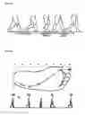
FIG. 2 illustrates the natural flow of force through the foot in more detail. The flow of force begins slightly to the side in the heel and then flows forward between the first and second metatarsal bones and exits the foot through the big toe.
Numerous authors who have addressed problems relating to heath, particularly problems of the lower extremities in humans, are convinced through their own observations that precisely those disabilities which are frequently encountered in humans who wear shoes consistently and for long periods are absent in the feet of primitive peoples who do not wear shoes: hallux valgus, plantar fasciitis, bunions, hammertoe, and generally painful feet are typical examples of such disabilities.
In short, it may be stated that in societies in which shoes are not worn, the foot muscles have freedom of movement and the joints remain flexible. Therefore, functional disorders are found in these humans only extremely rarely.
In shoe-wearing humans, shoes commonly limit the natural movements of the foot and the sequences for adaptive muscle activation required for stabilization of the foot structure before and during full weight bearing and during toe-off.
Various rehabilitative insoles have been proposed for alleviating the health problems described above. For example, U.S. Pat. No. 5,404,659 suggests an insole for a shoe in which a very extensive dome-shaped structure is provided for stimulating the golgi tendon organ. This dome-shaped structure makes up almost 50% of the entire surface area of the insole and accordingly forces the foot into a concave compulsory posture enclosing the arch. A disadvantage in this known insole is the inhibition of the windlass effect described and, therefore, of the final and very important part of the stance phase: the propulsive phase. With its dome-shaped structure, the known insole aims at a region defined as the apex of the arch of the foot by the lateral cuneiform, cuboid and navicular bones. However, in the inventor's opinion, the dynamic locking/unlocking of the cuboid bone, which is inhibited by the known insole, is fundamentally important for a natural gait with shoes. Since the peroneus longus embraces the cuboid, it is important that the cuboid yields. Otherwise, the peroneus is weakened. This highlights the inventor's insight that it is important to assist the foot in optimally performing the function intended for it by nature rather than artificially build up the foot posture enclosing the arch by an excessively large dome-shaped structure. Further, it has been shown that it is rather uncomfortable to wear a shoe having the known insole.
European patent applications EP 1 041 947 and EP 1 423 062 referred to as the prior art coming closest ultimately attempt to optimize the insole suggested in U.S. Pat. No. 5,404,659. In both cases, however, a very extensive dome-shaped structure is proposed which has the disadvantages already mentioned above; in both cases, the golgi tendon organ is to be stimulated by a dome-shaped structure whose target is defined by the point of articulation of the lateral cuneiform, cuboid and navicular bones. This also applies to US 2002/0014024 A1 by the same applicant.
U.S. Pat. No. 2,423,622 A discloses a flat shoe insole having a virtually square-shaped elevation exactly and exclusively beneath the cuboid bone of the shoe wearer which is aligned laterally alongside the longitudinal axis of the suggested shoe insole. To this extent, the known shoe insole is the prior art coming closest to the present invention because it is designed entirely correctly insofar as the basic idea is concerned and was merely unable to take into account the current insights of the inventor which underlie the present invention or fundamentally new considerations spanning more than 60 years. The document, which was certainly already very much ahead of its time, completely overcomes the misleading teachings of U.S. Pat. No. 2,287,341 A according to which a shoe insole has elevations on the outer side in the elongated position of the cuboid of the shoe wearer. The inventor is convinced that shoe insoles designed in this way have poor health benefits.
U.S. Pat. No. 3,421,518 A likewise suggests an elevation on the outer side in the elongated position of the cuboid bone of the shoe wearer for the insole of a shoe and therefore, with respect to medical engineering, does not go beyond the insights and disclosures of the above-cited U.S. Pat. No. 2,287,341 A.
The technical teaching of U.S. Pat. No. 2,154,997 A consists in the construction of a bottom foot lining in the elongated position of the cuboid bone of the shoe wearer which is now not only on the outer side but over the full width of the foot. This inhibits any inward rolling of the foot during the contact phase and is quite uncomfortable to wear because it is contrary to the natural gait. Further, a comparable teaching is disclosed in U.S. Pat. No. 2,421,088 A. In this respect, it remains to be noted that constructions such as these are diametrically opposed to the present invention.
Finally, reference is made to U.S. Pat. No. 6,510,626 B1 which, with respect to the insole for a shoe, likewise merely discloses outside elevations in the elongated position of the cuboid bone of the shoe wearer and to this extent does not go beyond the disclosures of U.S. Pat. No. 2,287,341 A and U.S. Pat. No. 3,421,518 A.
SUMMARY OF THE INVENTION
After intensive observations in everyday practice as a chiropractor, the inventor became convinced that all of the references evaluated above either lead away from the solution to the underlying problem or at least do not solve it convincingly. This problem can be summarized by the object of making available to the public an insole for a shoe which enables natural walking without pain or fatigue.
According to one embodiment of the invention, the problem is solved by an insole for a shoe, wherein the insole has a flat back side in direction of the shoe outsole and a dome-shaped structure (12) on the front side, and wherein
-
- the dome-shaped structure (12) has a base surface of a maximum of 25% of the insole surface,
- the dome-shaped structure (12) is positioned under the cuboid bone (4) of the shoe wearer,
wherein the insole according to the invention for a shoe is characterized by the following features: - a longitudinal axis (16) can be associated with the dome-shaped structure (12) at its apex, wherein the longitudinal axis (16) of the dome-shaped structure (12) encloses an angle (φ) in a range from 5° to 75° with the longitudinal axis of the insole.
A particularly preferred range for the angle (φ) between the longitudinal axis (16) of the dome-shaped structure (12) and the longitudinal axis of the insole is from 5° to 50°, particularly preferably from 5° to 35°.
BRIEF DESCRIPTION OF THE DRAWINGS
FIG. 1 depicts walking motion;
FIG. 2 depicts contact points of a foot during the walking motion of FIG. 1;
FIG. 3 is skelton a human foot;
FIG. 4 is skelton a human foot;
FIG. 5 is a truncated cone.
DETAILED DESCRIPTION OF THE PREFERRED EMBODIMENTS
In a preferred embodiment form, the dome-shaped structure (12) (FIG. 5) of the insole according to the invention is positioned under the medial side of the cuboid bone (4) of the shoe wearer where the cuboid bone (4) borders the navicular bone (3) on one side and the calcaneus bone (2) on the other side (FIG. 3). In this connection, reference is made on the one hand to FIG. 3 which shows the bone structure of a human foot and names all of the important bones mentioned herein. On the other hand, reference is made to FIG. 4 which likewise shows the human foot in which all of the bones essential to the invention are designated and, further, shows the goal of the dome-shaped structure corresponding to the present invention in one of the preferred embodiments thereof.
The dome-shaped structure (12) (FIG. 5) is constructed to be elastic. It is produced from permanently elastic plastics and/or gel materials, constructional variations of various hardness being preferred. It was shown in numerous trials upon which the present document is based that in a preferred embodiment the base surface of the dome-shaped structure (12) of the insole according to the invention for a shoe can even have a base surface of only a maximum of 20%, or even a maximum of 15%, of the insole surface. In particularly preferred embodiments, it is even possible to reduce the base surface of the dome-shaped structure (12) to a surface of 10% or less, particularly preferably even to a surface in a range from less than 4% to 8%, of the insole surface. In this case, however, the wearer of a shoe of this kind should train intensively to run on these insoles according to the invention with dome-shaped structure (12) which have a particularly drastically reduced base surface because otherwise it could be less comfortable under certain circumstances.
The dome-shaped structure (12) is generally constructed in the form of a truncated cone or truncated pyramid which is rounded on the base side and apex side. The height (15) of the dome-shaped structure (12) is preferably in a range from 3 to 20 mm. The rounded apex (13) of the truncated cone or truncated pyramid facing the cuboid bone (4) of the shoe wearer can accordingly be circular or square. In an embodiment form, which is particularly preferred and which is considered by the inventor to be the best, the truncated cone or truncated pyramid has a rectangle or an ellipse at least at its rounded apex (13) facing the cuboid bone (4) of the shoe wearer, wherein the rectangle or ellipse has a longitudinal-transverse ratio in a range of 1:1, or greater than 1:1, to 4:1 and particularly preferably in a range of 1.2:1 to 3:1.
When the truncated cone or truncated pyramid has a rectangle or ellipse at its rounded apex (13) facing the cuboid bone (4) of the shoe wearer with a longitudinal-transverse ratio at least in a range of 1:1, or greater than 1:1, to 4:1, it was shown to be particularly effective in the trials upon which the present document is based when the longitudinal axis (16) of the dome-shaped structure (12) extends along the medial edge of the cuboid bone (4) and particularly and preferably then encloses an angle (φ) of 5° to 35°, particularly preferably an angle (φ) of 25° to 35°, with the longitudinal axis of the insole.
For an illustration of the dome-shaped structure (12) as truncated cone, reference is made particularly to FIG. 5 which shows a corresponding truncated cone. The position of the angle (φ) is illustrated particularly in FIG. 4.
In a first possible constructional variant of the insole according to the invention, this insole is permanently connected to the dome-shaped structure (12). This can be achieved in that the insole and dome-shaped structure (12) are fabricated separately and subsequently indissolubly glued; this can also be achieved in that the insole and dome-shaped structure (12) are cast integral from a suitable plastics material without limiting in any way to these two possibilities.
In a second possible constructional variant of the insole according to one embodiment of the invention, the insole and dome-shaped structure (12) both have connection components, and the connection components of the insole are formed with the connection components of the dome-shaped structure (12) in such a way that insole and dome-shaped structure (12) are connected to one another so as to be difficult to detach. This detachability is desirable when the possibility of exchanging the dome-shaped structure (12) while retaining the insole is afforded as is preferred by the inventor. When exchange of the dome-shaped structure (12) is possible, the latter can be replaced in a particularly simple and convenient manner in case of wear or when a different hardness and/or a different outer shape or dimension is desired.
In this case, the connection components between insole and dome-shaped structure (12) are preferably selected from the list comprising: hook-and-loop strips; recessed grooves in the insole and springs engaging in the grooves under the base (14) of the dome-shaped structure (12); and recessed grooves in the base (14) of the dome-shaped structure (12) and springs engaging in the grooves at the front side of the insole.
In case recessed grooves in the insole are selected as connection components between insole and dome-shaped structure (12), a preferred embodiment these recessed grooves in the insole extend at an angle of 80° to 100° to the longitudinal axis (16) of the dome-shaped structure (12). Given this choice of angle at which the recessed grooves in the insole and the springs engaging in the grooves in a corresponding manner below the base (14) of the dome-shaped structure (12) extend virtually at right angles to the longitudinal axis (16) of the dome-shaped structure (12), the insole and dome-shaped structure (12) are connected to one another in a particularly resistant manner so that such an alignment of grooves and springs is particularly suitable for athletic shoes. In a particularly preferred constructional variant of the described embodiment form, the grooves which are recessed in the insole extend up to at least an outer edge of the insole so that the springs below the base (14) of the dome-shaped structure (12) can be inserted into the recessed grooves of the insole proceeding from the outer edge of the insole.
In case recessed grooves in the base (14) of the dome-shaped structure (12) are selected as connection components between insole and dome-shaped structure (12), it is preferable when these recessed grooves extend along the longitudinal axis (16) of the dome-shaped structure (12). The springs corresponding to the recessed grooves along the longitudinal axis (16) of the dome-shaped structure (12) are formed on the front side of the insole. Insofar as the grooves are guided into the base (14) of the dome-shaped structure (12) up to the outer edge of the dome-shaped structure (12), it is particularly simple and convenient to insert the grooves proceeding from the end of the springs. Snap-in elements in the grooves and associated springs prevent an unintentional slipping of the dome-shaped structure (12) relative to the insole on one hand and facilitate an exact alignment of the dome-shaped structure (12) relative to the insole on the other hand.
Insofar as the connection components between the insole and dome-shaped structure (12) are realized by grooves and springs to be inserted into the grooves, it is particularly preferable when the recessed grooves are undercut and the springs are formed so as to widen outward in a corresponding manner.
In another preferred embodiment, the construction of the dome-shaped structure (12) and the connection thereof to the insole is realized by a preferably three-part component structure comprising base, center piece and dome. In this case, the base which is generally made from an inelastic, durable plastic or from carbon fibers is positioned under the insole ideally in the middle of a bottom structure of the insole which corresponds in an exactly fitting manner to the base and which receives the base, and the base comprises connection elements for connecting to the center piece by frictional engagement. These connection elements for connecting base and center piece by frictional engagement can be constructed, for example, as matching eyelet/pin elements having a snap-in function.
Like the base, the center piece itself is preferably produced from an inelastic, durable plastic or from carbon fibers and is positioned above the base in the plane of the insole; to this end, the insole has a continuous hole in the outer shape of the center piece. Ideally, the center piece can be inserted by guiding through the hole in the insole in an exactly fitting manner from above until it is pressed onto the base for connecting to the latter.
On top, the center piece preferably has: either at least one recessed groove, in which case the dome has the at least one matching spring engaging in this groove, or at least one spring, in which case the dome has the at least one matching groove in which the spring of the center piece can engage.
The above-mentioned dome is constructed so as to be elastic and, for example, is produced from permanently elastic plastic and/or from gel material which may be covered with a suitable outer material if required.
In a specific instance of the preferred embodiment form described above, the base and center piece can also be constructed as a cohesive workpiece which is either assembled before being inserted in an exactly fitting manner through the hole in the insole, this time from below, from the two individually fabricated pieces, base and center piece, and possibly glued, or is fabricated directly in one piece, in which case this workpiece has a bottom part as base and a top part as center piece.
It is possible to form the insole as an integral component part of a shoe. In this case, the insole according to the invention is glued and/or sewed to the outsole of a shoe and, as the case may be, also to the outer material of this shoe.
In a particularly preferred embodiment form of the present invention, it is also possible that the insole is constructed as an insert for certain shoes. In this case, it is also possible for the insole to be produced and offered as a so-called 314 sole which can be fastened to a complete insole inside a specific shoe by means of double-sided adhesive tapes. In so doing, it is common to shorten ¾ soles of this kind in the front and, if necessary, on the sides until they fit into the given shoe.
Thus, while there have shown and described and pointed out fundamental novel features of the invention as applied to a preferred embodiment thereof, it will be understood that various omissions and substitutions and changes in the form and details of the devices illustrated, and in their operation, may be made by those skilled in the art without departing from the spirit of the invention. For example, it is expressly intended that all combinations of those elements and/or method steps which perform substantially the same function in substantially the same way to achieve the same results are within the scope of the invention. Moreover, it should be recognized that structures and/or elements and/or method steps shown and/or described in connection with any disclosed form or embodiment of the invention may be incorporated in any other disclosed or described or suggested form or embodiment as a general matter of design choice. It is the intention, therefore, to be limited only as indicated by the scope of the claims appended hereto.
Claims
1.-15. (canceled)
16. An insole for a shoe, comprising:
a back side configured to face a shoe outsole;
a front side opposite the back side;
a dome-shaped structure arranged on the front side having a base surface being a maximum of 25% of the insole surface positioned substantially under a cuboid bone of a shoe wearer; and
a longitudinal axis associated with the dome-shaped structure at an apex of the shaped structure, wherein the longitudinal axis of the dome-shaped structure encloses an angle having a range from about 5° to about 75° with a longitudinal axis of the insole.
17. The insole according to claim 16, wherein the dome-shaped structure is positioned under a medial side of the cuboid bone of the shoe wearer where the cuboid bone borders a navicular bone on one side and a calcaneus bone on an other side.
18. The insole according to claim 16, wherein the base surface is a maximum of 15%, of the insole surface.
19. The insole according to claim 16, wherein the base surface is a maximum of 10%, of the insole surface.
20. The insole according to claim 16, wherein the dome-shaped structure has a longitudinal-transverse ratio in a range from about 1.2:1 to about 3:1.
21. The insole according to claim 21, wherein the longitudinal axis of the dome-shaped structure extends along a medial edge of the cuboid bone and encloses an angle of 5° to 35° with the longitudinal axis of the insole.
22. The insole according to claim 16, wherein the dome-shaped structure has a height in a range from about 3 mm to about 20 mm.
23. The insole according to claim 16, wherein the dome-shaped structure is permanently connected to the insole.
24. The insole according to claim 16, wherein each of the insole and the dome-shaped structure have a respective connection components, wherein the connection component of the insole are formed with the connection components of the dome-shaped structure for detachable connection of insole and dome-shaped structure.
25. The insole according to claim 24, wherein the connection components are at least one of hook-and-loop strips, recessed grooves in the insole and springs engaging in the grooves under the base of the dome-shaped structure, and recessed grooves in the base of the dome-shaped structure and springs engaging in the grooves at the front side of the insole.
26. The insole according to claim 25, wherein the recessed grooves in the insole extend at an angle of about 80° to about 100° to the longitudinal axis of the dome-shaped structure.
27. The insole according to claim 25, wherein the recessed grooves in the base of the dome-shaped structure extend along the longitudinal axis of the dome-shaped structure.
28. The insole according to claim 25, wherein the respective recessed grooves are undercut and the respective springs are formed to widen outward.
29. The insole according to claim 16, wherein the insole is produced as an insert for certain shoes.
30. The insole according to claim 16, wherein the insole is an integral component part of the shoe.
Images & Drawings included:


Sources:
- United States Patent and Trademark Office - verify current appl. status at the USPTO↗
Similar patent applications:
- » 20150059203
METHOD OF MANUFACTURING SHOE INSOLES AND SHOE INSOLE - » 20240138520
Shoe insole and processing method for shoe insole - » 20220312894
Shoe insole and processing method for shoe insole - » 20140326085
Shoe insole sensor for walk diagnosis and shoe insole flexible board combined with the same - » 20060201011
Foot tilt angle measuring method, method of selecting shoe or insole for shoe method of manufacturing shoe or insole for shoe, and foot unit tilt angle measuring device - » 20220322785
SHOE INSOLE AND SHOE WITH INSOLE STRUCTURE - » 20100229422
Customized shoe and insole, method and apparatus for determining shape of a foot and for making a shoe or insole - » 20070033834
Shoe insole - » 20050166425
Shoe insole for diabetics - » 20070126146
Method for manufacturing composite shoe insole
Recent applications in this class:
- » 20240148102 2024-05-09
WALKING BOOT INSERT FOR WOUND CARE - » 20240041156 2024-02-08
ANKLE FOOT ORTHOTIC ASSEMBLY - » 20210274880 2021-09-09
Kompressor: Footwear with computer controlled individually configurable inflatable air bladder orthotic and non-orthotic structures. - » 20210120908 2021-04-29
CUSTOMIZABLE SHOE INSERT - » 20200281307 2020-09-10
FUNCTIONAL ORTHOTIC SUPPORT STRUCTURE FOR FOOTWEAR - » 20190320758 2019-10-24
Functional orthotic support structure for footwear - » 20120233877 2012-09-20
HIGH-STABILITY MULTI-DENSITY MIDSOLE - » 20120040803 2012-02-16
ACHILLES STRETCHING DEVICES AND METHODS PERFORMED THEREWITH - » 20100242310 2010-09-30
ACHILLES AND FOOT ARCH STRETCHING DEVICES AND METHODS PERFORMED THEREWITH - » 20100218398 2010-09-02
Insole comprising a curve support