HEAT DISSIPATION DEVICE
US20120160462A1
2012-06-28
12/981,438
2010-12-29
Abstract:
A heat dissipation device for dissipating heat from an electronic component, includes a heat sink, a centrifugal fan disposed on the heat sink, and a cover board covering the heat sink and located above the centrifugal fan. The cover board defines a plurality of through holes acting as air-intakes of the centrifugal fan.
Assignee:
- HON HAI PRECISION INDUSTRY CO., LTD. 12,828 🇹🇼 Tu-Cheng, Taiwan
Interested in similar patents?
Get notified when new applications in this technology area are published.
Classification:
H01L23/467 » CPC main
Details of semiconductor or other solid state devices; Arrangements for cooling, heating, ventilating or temperature compensation ; Temperature sensing arrangements involving the transfer of heat by flowing fluids by flowing gases, e.g. air
F28D2021/0029 » CPC further
Heat-exchange apparatus not covered by any of the groups - ; Other heat exchangers for particular applications; Heat exchange systems not otherwise provided for for cooling heat generating elements, e.g. for cooling electronic components or electric devices Heat sinks
F28F3/048 » CPC further
Plate-like or laminated elements; Assemblies of plate-like or laminated elements; Elements or assemblies thereof with means for increasing heat-transfer area, e.g. with fins, with recesses, with corrugations the means being integral with the element in the form of ribs integral with the element or local variations in thickness of the element, e.g. grooves, microchannels
H01L2924/0002 » CPC further
Indexing scheme for arrangements or methods for connecting or disconnecting semiconductor or solid-state bodies as covered by; Technical content checked by a classifier Not covered by any one of groups , and
H01L2924/00 » CPC further
Indexing scheme for arrangements or methods for connecting or disconnecting semiconductor or solid-state bodies as covered by
F28F13/00 IPC
Arrangements for modifying heat-transfer, e.g. increasing, decreasing
Description
BACKGROUND
1. Technical Field
The disclosure relates to heat dissipation, and particularly to a heat dissipation device with low noise.
2. Description of Related Art
Electronic components, such as memory banks comprise numerous circuits operating at high speeds and generating substantial amount of heat. Under most circumstances, it is necessary to cool the memory banks to maintain safe operating conditions and assure that the memory banks function properly and reliably. In the past, various approaches have been used to cool electronic components. Typically, a fan is provided to the casing where the memory banks are disposed, which generates airflow towards the memory banks. However, in use, the fan may make a lot of noise.
What is needed, therefore, is a heat dissipation device with low noise.
BRIEF DESCRIPTION OF THE DRAWINGS
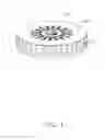
FIG. 1 is an isometric, assembled view of a heat dissipation device in accordance with an embodiment of the disclosure.
FIG. 2 is an exploded view of FIG. 1.
DETAILED DESCRIPTION
Referring to FIGS. 1-2, a heat dissipation device in accordance with an exemplary embodiment of the disclosure is disclosed. The heat dissipation device dissipates heat from an electronic component (not shown) mounted on a printed circuit board (not shown). The heat dissipation device comprises a heat sink 10, a centrifugal fan 20 disposed on the heat sink 10, and a cover board 30 covering the heat sink 10 and located above the centrifugal fan 20.
The heat sink 10 is integrally made of a material with high heat conductivity, such as copper, aluminum or an alloy thereof. The heat sink 10 comprises a base 12 and a plurality of fins 14 extending upwardly from a top face of the base 12. The base 12 is a flat, circular plate. A bottom face of the base 12 is attached to the electronic component. A circular receiving portion 16 is defined by the top face of the base 12 and inner circumferential peripheries of the fins 14. The fins 14 are arranged radially relative to the receiving portion 16. The fins 14 are generally perpendicular to the base 12. The fins 14 are spaced from each other. A passage (not labeled) is defined between every two neighboring fins 14 for an airflow flowing through.
The centrifugal fan 20 comprises a rotation axis 22, a magnetic member 24 mounted on the rotation axis 22, a mounting ring 26, and an impeller 28 rotatably engaging with the rotation axis 22. The centrifugal fan 20 is received in the receiving portion 16 of the heat sink 10. A height of the centrifugal fan 20 is slightly less than that of each fin 14 of the heat sink 10. The rotation axis 22 is perpendicular to the base 12 of the heat sink 10.
The cover board 30 is integrally made of a material with high heat conductivity, such as copper, aluminum or an alloy thereof. The cover board 30 is circular, flat, and thin. A circular hole 32 is defined at a center of the cover board 30. A plurality of through holes 34 are defined in the cover board 30. The through holes 34 are correspondingly located above the impeller 28 of the centrifugal fan 20. The through holes 34 are spaced from each other, and arranged evenly relative to the center of the cover board 30. In this embodiment, the through holes 34 are arranged radially relative to the center of the cover board 30. The cover board 30 is attached to top faces of the fins 14 of the heat sink 10. In use, the through holes 34 act as air-intakes of the centrifugal fan 20, and airflow generated by the centrifugal fan 20 directly flow through the passages of the fins 14 of the heat sink 10. The through holes 34 arranged around the circular hole 32 can effectively reduce noise generated by the impeller 28, whereby the heat dissipation device has a quiet working status.
It is to be understood, however, that even though numerous characteristics and advantages of certain embodiments have been set forth in the foregoing description, together with details of the structures and functions of the embodiments, the disclosure is illustrative only, and changes may be made in detail, especially in matters of shape, size, and arrangement of parts within the principles of the disclosure to the full extent indicated by the broad general meaning of the terms in which the appended claims are expressed.
Claims
What is claimed is:1. A heat dissipation device comprising:
a heat sink;
a centrifugal fan disposed on the heat sink; and
a cover board covering the heat sink and located above the centrifugal fan; wherein
the cover board defines a plurality of through holes acting as air-intakes of the centrifugal fan.
2. The heat dissipation device of claim 1, wherein the heat sink comprises a base and a plurality of fins extending upwardly from a top face of the base.
3. The heat dissipation device of claim 2, wherein a receiving portion is defined by the top face of the base and inner circumferential peripheries of the fins.
4. The heat dissipation device of claim 3, wherein the fan is received in the receiving portion.
5. The heat dissipation device of claim 4, wherein a height of the centrifugal fan is less than that of each fin of the heat sink.
6. The heat dissipation device of claim 3, wherein the fins are arranged radially relative to the receiving portion.
7. The heat dissipation device of claim 2, wherein the fins are spaced from each other, and a passage is defined between every two neighboring fins.
8. The heat dissipation device of claim 7, wherein airflow generated by the centrifugal fan directly flow through the passages of the fins.
9. The heat dissipation device of claim 1, wherein the centrifugal fan comprises a rotation axis, a magnetic member mounted on the rotation axis, a mounting ring, and an impeller rotatably engaging with the rotation axis.
10. The heat dissipation device of claim 9, wherein the rotation axis is perpendicular to the base of the heat sink.
11. The heat dissipation device of claim 1, wherein the through holes are located above the centrifugal fan.
12. The heat dissipation device of claim 1, wherein the through holes are spaced from each other.
13. The heat dissipation device of claim 1, wherein the through holes are arranged radially relative to a center of the cover board.
14. The heat dissipation device of claim 1, wherein a circular hole is defined at a center of the cover board.
15. The heat dissipation device of claim 1, wherein the cover board is attached to a top side of the heat sink.
Images & Drawings included:


Sources:
- United States Patent and Trademark Office - verify current appl. status at the USPTO↗
Similar patent applications:
- » 20190212793
Heat dissipation device, heat dissipation assembly, air pipe assembly, and table having heat dissipation device - » 20120147561
HEAT DISSIPATION DEVICE, HEAT DISSIPATION METHOD FOR COMMUNICATION DEVICE, AND COMMUNICATION DEVICE - » 20190186840
Basic structural body for constructing heat dissipation device and heat dissipation device - » 20230209776
HEAT DISSIPATION DEVICE AND HEAT DISSIPATION DEVICE ASSEMBLING METHOD - » 20220412666
BASIC STRUCTURAL BODY FOR CONSTRUCTING HEAT DISSIPATION DEVICE AND HEAT DISSIPATION DEVICE - » 20230055030
BASIC STRUCTURAL BODY FOR CONSTRUCTING HEAT DISSIPATION DEVICE AND HEAT DISSIPATION DEVICE - » 20210315134
Heat dissipation device, heat dissipation method and terminal - » 20190285357
MIDDLE MEMBER OF HEAT DISSIPATION DEVICE AND THE HEAT DISSIPATION DEVICE - » 20080142193
METHOD OF MANUFACTURING A HEAT DISSIPATION DEVICE AND A HEAT DISSIPATION DEVICE OBTAINED THEREBY - » 20190285353
Middle member of heat dissipation device and the heat dissipation device
Recent applications in this class:
- » 20250157882 2025-05-15
SYSTEMS AND METHODS FOR COOLING AN INTEGRATED CIRCUIT - » 20250087556 2025-03-13
Optimization of the thermal performance of the 3D ICs utilizing the integrated chip-size double-layer or multi-layer microchannels - » 20240413054 2024-12-12
INTEGRATED CIRCUIT PACKAGES WITH FLUID SPACERS TO IMPROVE PIN LOAD DISTRIBUTION - » 20240170368 2024-05-23
Choked flow cooling - » 20240162115 2024-05-16
SEMICONDUCTOR PACKAGE AND SEMICONDUCTOR DEVICE INCLUDING THE SAME - » 20240145341 2024-05-02
MANAGEMENT OF HEAT ON A SEMICONDUCTOR DEVICE AND METHODS FOR PRODUCING THE SAME - » 20240071867 2024-02-29
Data storage structure or data infrastructure including a plurality of storage device preliminary class - » 20240006269 2024-01-04
Optimization of the thermal performance of the 3D ICs utilizing the integrated chip-size double-layer or multi-layer microchannels - » 20230378024 2023-11-23
SEMICONDUCTOR PACKAGE STRUCTURES AND METHODS OF FORMING THE SAME - » 20230335462 2023-10-19
THREE-DIMENSIONAL DEVICE COOLING
Recent applications for this Assignee:
- » 20140233961 2014-08-21
Optical communication module including optical-electrical signal converters and optical signal generators - » 20140083669 2014-03-27
HEAT SINK - » 20140063746 2014-03-06
Electronic device with heat dissipation assembly - » 20140061224 2014-03-06
AUTOMATIC VENDING MACHINE - » 20140060914 2014-03-06
Enclosure with shield apparatus - » 20140058727 2014-02-27
MULTIMEDIA RECORDING SYSTEM AND METHOD - » 20140055955 2014-02-27
Fastener - » 20140055322 2014-02-27
DISPLAY SYSTEM AND HEAD-MOUNTED DISPLAY APPARATUS - » 20140054439 2014-02-27
CONTAINER DATA CENTER WITH SUPPORTING APPARATUS - » 20140054311 2014-02-27
AUTOMATIC VENDING MACHINE WITH MOVING MEMBER FOR PRODUCTS