MOUNTING DEVICE FOR FAN
US20120163989A1
2012-06-28
12/980,336
2010-12-29
Abstract:
A mounting device for fan includes a frame for receiving the fan, and a rack for receiving the frame.
Assignee:
- HON HAI PRECISION INDUSTRY CO., LTD. 12,828 🇹🇼 Tu-Cheng, Taiwan
Interested in similar patents?
Get notified when new applications in this technology area are published.
Classification:
H05K7/20172 » CPC main
Constructional details common to different types of electric apparatus; Modifications to facilitate cooling, ventilating, or heating using a gaseous coolant in electronic enclosures; Forced ventilation, e.g. by fans Fan mounting or fan specifications
H05K7/20172 » CPC main
Constructional details common to different types of electric apparatus; Modifications to facilitate cooling, ventilating, or heating using a gaseous coolant in electronic enclosures; Forced ventilation, e.g. by fans Fan mounting or fan specifications
H05K7/20718 » CPC further
Constructional details common to different types of electric apparatus; Modifications to facilitate cooling, ventilating, or heating for server racks or cabinets; for data centers, e.g. 19-inch computer racks Forced ventilation of a gaseous coolant
H05K7/20718 » CPC further
Constructional details common to different types of electric apparatus; Modifications to facilitate cooling, ventilating, or heating for server racks or cabinets; for data centers, e.g. 19-inch computer racks Forced ventilation of a gaseous coolant
F04D29/00 IPC
Details, component parts, or accessories
Description
BACKGROUND
1. Technical Field
The present disclosure relates to a mounting device for a fan.
2. Description of Related Art
The size of racks for fixing fans in a computer is standard. Thus, the racks can only hold standard size fans, therefore fans with a smaller then standard size cannot be fitted in the rack, which is inconvenient.
BRIEF DESCRIPTION OF THE DRAWINGS
Many aspects of the present embodiments can be better understood with reference to the following drawings. The components in the drawings are not necessarily drawn to scale, the emphasis instead being placed upon clearly illustrating the principles of the present embodiments. Moreover, in the drawings, all the views are schematic, and like reference numerals designate corresponding parts throughout the several views.
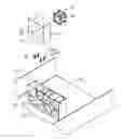
FIG. 1 is an assembled, isometric view of an exemplary embodiment of a mounting device for a fan, together with a fan having a small size.
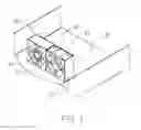
FIG. 2 is an exploded, isometric view of the mounting device of FIG. 1.
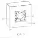
FIG. 3 is an enlarged view of the fan installed in a frame of the mounting device of FIG. 1.
DETAILED DESCRIPTION
The disclosure, including the accompanying drawings, is illustrated by way of example and not by way of limitation. It should be noted that references to “an” or “one” embodiment in this disclosure are not necessarily to the same embodiment, and such references mean at least one.
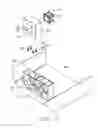
Referring to FIG. 2, an exemplary embodiment of a mounting device for a fan is mounted in a chassis of an electronic device, such as a server. The mounting device includes a rack 50, a frame 20, and a plurality of screws 30. The mounting device is used for mounting a fan 10 with smaller than standard size in the rack 50.
The fan 10 includes two spaced rectangular-shaped boards 12.
The rack 50 is hollow and substantially rectangular-shaped, which is mounted on a bottom board 40 of the chassis. The rack 50 defines a receiving space 54 therein, with an opening 52 of the receiving space 54 opposite to the bottom board 40 of the chassis.
The frame 20 is substantially rectangular-shaped, and defines a receiving space 22 extending through opposite sides of the frame 20. A through hole 26 is defined in each corner of a bottom wall 24 bounding the receiving space 22. The size of the frame 20 is suitable to be received in the receiving space 54 of the rack 50.
Each screw 30 includes a head 32, and a post 34 extending from a center of the head 32. A thread portion 36 is formed on the post 34 adjacent to the head 32.
Referring to FIG. 1 and FIG. 3, in assembly, the fan 10 is received in the receiving space 22 of the frame 20. The threaded portion 36 of the posts 34 of the screws 30 are screwed in the corresponding through holes 26 of the frame 20 from a bottom of the bottom wall 24, with distal ends of the posts 34 extending into the receiving space 22. The distal ends of the posts 34 resist against inner sides of the corresponding boards 12 of the fan 10. Thereby, the fan 10 is fixed in the receiving space 22 of the frame 20.
The frame 20 together with the fan 10 enters the receiving space 54 of the rack 50 through the opening 52. A plurality of screws or other fixing members fix the frame 20 to the rack 50. When the right size fan 60 has been fitted to the rack 50, the frame 20 can be omitted.
It is believed that the present embodiments and their advantages will be understood from the foregoing description, and they will be apparent that various changes may be made thereto without departing from the spirit and scope of the description or sacrificing all of their material advantages, the examples hereinbefore described merely being exemplary embodiment.
Claims
What is claimed is:1. A mounting device for a fan, the mounting device comprising:
a frame for receiving the fan; and
a rack for receiving the frame.
2. The mounting device of claim 1, wherein the frame defines a first receiving space extends through opposite sides of the frame for receiving the fan, and defines a plurality of through holes in a bottom wall bounding the first receiving space, a plurality of fasteners extend through the corresponding through holes to position the fan.
3. The mounting device of claim 2, wherein the fasteners are screws, each screw comprises a head and a post extending from the head, a thread portion is formed on the post adjacent to the head, the threaded portion is screwed in the corresponding through hole of the frame, a distal end of the screw opposite to the head extends into the receiving space to resist against the fan.
4. The mounting device of claim 1, wherein a second receiving space with an opening is defined in the rack, the frame enters the second receiving space of the rack through the opening.
Images & Drawings included:
Sources:
- United States Patent and Trademark Office - verify current appl. status at the USPTO↗
Similar patent applications:
- » 20150139793
COOLING FAN MOUNTING DEVICE AND IMAGE FORMING APPARATUS INCLUDING SAME - » 20070103872
Heat sink assembly having a fan mounting device - » 20240314984
POWER SUPPLY WITH EXTERNALLY MOUNTED FAN DEVICE - » 20080128110
HEAT SINK ASSEMBLY HAVING A FAN MOUNTING DEVICE - » 20120156030
Mounting device for fan and fan module with the same - » 20130142642
Mounting device for fan - » 20130255987
MOUNTING DEVICE FOR FAN - » 20130108435
MOUNTING DEVICE FOR FAN - » 20130068922
MOUNTING DEVICE FOR FAN - » 20130087310
MOUNTING DEVICE FOR FAN
Recent applications in this class:
- » 20250169025 2025-05-22
SLIDABLY PLUGGABLE MULTI-FAN MODULE AND SERVER COMPRISING SAME - » 20250169024 2025-05-22
Server System Fan System - » 20250151226 2025-05-08
HEAT DISSIPATION DEVICE AND COMPUTER DEVICE - » 20250142767 2025-05-01
LOW-NOISE FAN FOR INFORMATION HANDLING SYSTEMS - » 20250142766 2025-05-01
FAN ASSEMBLY AND ELECTRONIC DEVICE - » 20250133689 2025-04-24
CONTROL APPARATUS AND COOLING METHOD OF CONTROL APPARATUS - » 20250113463 2025-04-03
LASER LEVEL COOLING - » 20250113462 2025-04-03
CONFIGURABLE AIRFLOW DIRECTION FAN SYSTEM - » 20250113461 2025-04-03
Server Information Handling System with Reversible Airflow Fan System - » 20250107034 2025-03-27
DEVICE FOR COOLING ELECTRONIC EQUIPMENT
Recent applications for this Assignee:
- » 20140233961 2014-08-21
Optical communication module including optical-electrical signal converters and optical signal generators - » 20140083669 2014-03-27
HEAT SINK - » 20140063746 2014-03-06
Electronic device with heat dissipation assembly - » 20140061224 2014-03-06
AUTOMATIC VENDING MACHINE - » 20140060914 2014-03-06
Enclosure with shield apparatus - » 20140058727 2014-02-27
MULTIMEDIA RECORDING SYSTEM AND METHOD - » 20140055955 2014-02-27
Fastener - » 20140055322 2014-02-27
DISPLAY SYSTEM AND HEAD-MOUNTED DISPLAY APPARATUS - » 20140054439 2014-02-27
CONTAINER DATA CENTER WITH SUPPORTING APPARATUS - » 20140054311 2014-02-27
AUTOMATIC VENDING MACHINE WITH MOVING MEMBER FOR PRODUCTS