INDUCTION LIGHTING LUMINAIRE INSTALLATION
US20120188769A1
2012-07-26
13/352,309
2012-01-17
Abstract:
A new method and apparatus for installing replacement induction lamp envelopes into cobra-head lighting fixtures is presented, using a novel split reflector design that permits easy access to the lamp envelope compartment.
Interested in similar patents?
Get notified when new applications in this technology area are published.
Classification:
F21V17/107 » CPC main
Fastening of component parts of lighting devices, e.g. shades, globes, refractors, reflectors, filters, screens, grids or protective cages characterised by specific fastening means or way of fastening using hinge joints
F21V7/10 » CPC further
Reflectors for light sources Construction
F21V23/026 » CPC further
Arrangement of electric circuit elements in or on lighting devices the elements being transformers, impedances or power supply units, e.g. a transformer with a rectifier Fastening of transformers or ballasts
H01J65/046 » CPC further
Lamps without any electrode inside the vessel; Lamps with at least one main electrode outside the vessel; Lamps in which a gas filling is excited to luminesce by an external electromagnetic field or by external corpuscular radiation, e.g. for indicating plasma display panels by an external electromagnetic field the field being produced by using capacitive means around the vessel
F21W2111/02 » CPC further
Use or application of lighting devices or systems for signalling, marking or indicating, not provided for in codes – for roads, paths or the like
Y10T29/4973 » CPC further
Metal working; Method of mechanical manufacture; Repairing with disassembling Replacing of defective part
F21V21/26 IPC
Supporting, suspending, or attaching arrangements for lighting devices ; Hand grips; Adjustable mountings Pivoted arms
B23P6/00 IPC
Restoring or reconditioning objects
Description
RELATED APPLICATIONS
This application claims the benefit of U.S. Provisional Application 61/434,520 dated Jan. 20, 2011, whose contents are included by reference.
FIELD OF THE INVENTION
This invention is related to the field of induction lighting, used in both outdoor and indoor lighting.
BACKGROUND OF THE INVENTION
Induction lighting systems can last approximately 100,000 hours before replacement. They are used in applications such as street lighting fixtures that are generally described as a “cobra head”, because of their shape.
The typical street light cobra head arrangement accommodates a screw-in discharge bulb inserted into a lampholder. The proposed retrofit for these light systems involves substituting an induction lamp, a power coupler, and a high-frequency ballast. As the standard cobra-head enclosure is too short to make retrofit installation possible, a new enclosure is proposed to allow easy retrofit and replacement of the induction lamp system
OBJECTS OF THE INVENTION
It is an object of the present invention to provide a modified induction lighting luminaire enclosure.
It is the object of the present invention that the induction light luminaire enclosure be constructed with a split reflector.
It is a further object of this invention that said split reflector be opened by means of a hinge or by sliding out of the split reflector.
BRIEF DESCRIPTION OF THE FIGURES
FIG. 1. Reflector and HID lamp
FIG. 2. Cross-section of discharge lamp with bulb out
FIG. 3. Cross-section of discharge lamp with bulb inserted
FIG. 4. Induction lamp system
FIG. 5. Typical Cobra Head Reflector
FIG. 6. Split Reflector
FIG. 7. Open Fixture Housing
FIG. 8. Closed Fixture Housing
DETAILED DESCRIPTION
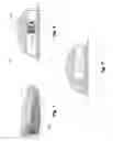
FIG. 1 through FIG. 3 show the general configuration of a cobra head discharge lamp lighting fixture 100. There is an upper housing 101 that contains an interior socket structure 110 within which a lamp 111 or light bulb can be mounted, ordinarily screwed into said socket 110 by means of screw threads 112. The street lighting fixture is closed by a transparent or translucent lens 102.
FIG. 4 shows the induction lamp system, including an induction lamp envelope 120, a power coupler 105 and a high-frequency ballast 113. There are other lamp shapes and configurations possible. These are the basic components of any induction lamp.
FIG. 5 shows a cobra head lamp enclosure 115 with a power coupler 105 installed. From inspection, the induction lamp envelope 120 cannot be easily installed within the enclosure 115 due to the power coupler 105 length. The enclosure 115 has to be removed or the power coupler 105 removed from the enclosure 115 to permit lamp 120 replacement
In FIG. 6, the split cobra head reflector is shown.
FIG. 7 shows the preferred embodiment of the invention, comprised of a hinged lens 110 with attached split reflector 109 and coupler 105 that can be swung up via the hinge 121 to permit installation of the induction lamp envelope 120, then swung back down to complete the installation and close the cobra head enclosure 115 as in FIG. 8.
An alternate embodiment of the invention would permit the split reflector 109 to be slid off the end of the cobra head enclosure 115 after the hinge 121 is swung up.
While the foregoing describes a preferred and an alternative embodiment of the invention, variation on this design and equivalent designs may be resorted to in the scope and spirit of the claimed invention.
Claims
What is claimed is:1. An induction lighting and lamp installation system, the induction lighting system comprised of an induction lamp envelope, a power coupler, and a high-frequency ballast,
the lamp installation system comprised of a lamp enclosure with a power coupler and a high frequency ballast installed within it, a split reflector, and a hinge,
one half of the split reflector containing the coupler and ballast and capable of being swung up via the hinge, the resulting opening in the lamp enclosure large enough to permit the mating of the induction lamp envelope with the power coupler.
2. The induction lighting and lamp installation system of claim 1 where the second half of the split reflector can be slid off the end of the lamp enclosure permitting installation of the induction lamp envelope with the power coupler.
3. A method of installing a replacement induction lamp envelope in a lamp enclosure in an induction lighting system as in claim 1 comprised of the steps of
opening the lamp enclosure by rotating half of the split reflector on the hinge,
removing the old induction lamp envelope from the power coupler,
placing a new induction lamp envelope over the power coupler,
closing the lamp enclosure by rotating the split reflector back into the lamp enclosure and latching it.
Images & Drawings included:


Sources:
- United States Patent and Trademark Office - verify current appl. status at the USPTO↗
Recent applications in this class:
- » 20240318808 2024-09-26
Illumination device with a living hinge - » 20240102635 2024-03-28
Flexible mat light - » 20230313979 2023-10-05
Joint assembly for luminaires - » 20220186914 2022-06-16
THREE-SECTION HINGEDLY CONNECTED LIGHTING PANEL - » 20210262642 2021-08-26
Stand and lighting device - » 20210190299 2021-06-24
LED luminaire - » 20210071848 2021-03-11
Neon lamp end cap boot and method of installation - » 20190353332 2019-11-21
Multi-Function Work Light - » 20180238523 2018-08-23
COLLAPSIBLE LED FIXTURE - » 20170114986 2017-04-27
LUMINAIRES