Handheld electronic device and function control method thereof
US20120212403A1
2012-08-23
13/151,284
2011-06-02
✅ Patent granted
US 8,471,813 B2
2013-06-25
-
-
Kevin M Nguyen | Kenneth B Lee, Jr.
Altis Law Group, Inc.
2032-02-07
Abstract:
A handheld electronic device is provided. The electronic device includes an electrode unit, a storage unit, and a processing unit. The electrode unit includes a main body defining an annular cavity, a plurality of electrode groups, and a conductive element arranged within the annular cavity, wherein each of the plurality of the electrode groups includes a pair of conductive sheets, which are partially received in the annular cavity and are spaced apart from each other. When the electronic device is rotated to be in different orientation, the conductive element connects different electrode groups and the conductive sheets of the one of the electrode groups are connected to each other via the conductive element. The processing unit determines the connected electrode groups and executes a function corresponding to the determined electrode group. A function control method of the handheld electronic device is also provided.
Inventors:
- JUN ZHANG 25 🇨🇳 Shenzhen City, China
- QI-LONG YU 6 🇨🇳 Shenzhen City, China
- JUN ZHANG 144 🇨🇳 Shenzhen, China
- QI-LONG YU 18 🇨🇳 Shenzhen, China
Assignee:
- HON HAI PRECISION INDUSTRY CO., LTD. 12,833 🇹🇼 Tu-Cheng, Taiwan
- FU TAI HUA INDUSTRY (SHENZHEN) CO., LTD. 489 🇨🇳 ShenZhen City, China
- HON HAI PRECISION INDUSTRY CO., LTD. 10,014 🇹🇼 New Taipei, Taiwan
- FU TAI HUA INDUSTRY (SHENZHEN) CO., LTD. 815 🇨🇳 Shenzhen, China
Applicant:
Interested in similar patents?
Get notified when new applications in this technology area are published.
Classification:
G06F3/033 IPC
Input arrangements for transferring data to be processed into a form capable of being handled by the computer; Output arrangements for transferring data from processing unit to output unit, e.g. interface arrangements; Input arrangements or combined input and output arrangements for interaction between user and computer; Arrangements for converting the position or the displacement of a member into a coded form Pointing devices displaced or positioned by the user, e.g. mice, trackballs, pens or joysticks ; Accessories therefor
G06F3/0346 » CPC main
Input arrangements for transferring data to be processed into a form capable of being handled by the computer; Output arrangements for transferring data from processing unit to output unit, e.g. interface arrangements; Input arrangements or combined input and output arrangements for interaction between user and computer; Arrangements for converting the position or the displacement of a member into a coded form; Pointing devices displaced or positioned by the user, e.g. mice, trackballs, pens or joysticks ; Accessories therefor with detection of the device orientation or free movement in a 3D space, e.g. 3D mice, 6-DOF [six degrees of freedom] pointers using gyroscopes, accelerometers or tilt-sensors
G01C9/10 » CPC further
Measuring inclination, e.g. by clinometers, by levels by using rolling bodies, e.g. spheres, cylinders, mercury droplets
G01D5/25 » CPC further
Mechanical means for transferring the output of a sensing member; Means for converting the output of a sensing member to another variable where the form or nature of the sensing member does not constrain the means for converting; Transducers not specially adapted for a specific variable using electric or magnetic means Selecting one or more conductors or channels from a plurality of conductors or channels, e.g. by closing contacts
G06F1/1694 » CPC further
Details not covered by groups - and; Constructional details or arrangements for portable computers; Constructional details or arrangements of portable computers not specific to the type of enclosures covered by groups - ; Constructional details or arrangements related to integrated I/O peripherals not covered by groups - the I/O peripheral being a single or a set of motion sensors for pointer control or gesture input obtained by sensing movements of the portable computer
G01C2009/105 » CPC further
Measuring inclination, e.g. by clinometers, by levels by using rolling bodies, e.g. spheres, cylinders, mercury droplets mercury droplets
G06F3/01 IPC
Input arrangements for transferring data to be processed into a form capable of being handled by the computer; Output arrangements for transferring data from processing unit to output unit, e.g. interface arrangements Input arrangements or combined input and output arrangements for interaction between user and computer
Description
BACKGROUND
1. Technical Field
The present disclosure relates to electronic devices, and particularly, to a handheld electronic device and a method for controlling the handheld device.
2. Description of Related Art
Keyboards, touch pads, and touch screens are widely used for inputting commands to electronic devices. A keyboard often takes up a relatively larger space of an electronic device. Touch pads and touch screens are relatively expensive. Therefore, a new manner for users to input commands to electronic devices is needed to solve the above mentioned problems.
BRIEF DESCRIPTION OF THE DRAWINGS
Many aspects of the present disclosure should be better understood with reference to the following drawings. The components in the drawings are not necessarily drawn to scale, the emphasis instead being placed upon clearly illustrating the principles of the present disclosure. Moreover, in the drawings, like reference numerals designate corresponding parts throughout the several views.
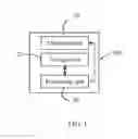
FIG. 1 is a block diagram of a handheld electronic device in accordance with an exemplary embodiment.
FIG. 2 is a schematic view of an electrode unit of the electronic device of FIG. 1.
FIGS. 3A-3B are schematic views showing the handheld electronic device of FIG. 1 in a horizontal state and an inclined state.
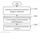
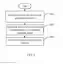
FIG. 4 is a flowchart of a function control method of the electronic device FIG. 1, in accordance with an exemplary embodiment.
DETAILED DESCRIPTION
Embodiments of the present disclosure will now be described in detail below, with reference to the accompanying drawings.
Referring to FIGS. 1-2, a handheld electronic device 100 includes an electrode unit 10, a storage unit 20, and a processing unit 30 electrically connected to the electrode unit 10 and the storage unit 20.
The electrode unit 10 is arranged inside the electronic device 100. In this embodiment, the electrode unit 10 is in a plane perpendicular to a surface of the electronic device 100 including a display (not shown). The electrode unit 10 includes a main body 101 defining an annular cavity 102, a number of electrode groups 103, and a conductive element 104 arranged within the annular cavity 102. Each electrode group 103 includes a pair of conductive sheets 1031, which are partially received in the annular cavity 102 and are spaced apart from each other, thus the resistance value between the two conductive sheets 1031 is infinite. The conductive element 104 can move along the annular cavity 102 when the electronic device 100 is rotated clockwise or anticlockwise. When the electronic device 100 is rotated to be in different orientations, the conductive element 104 moves to connect different electrode groups 103. When one electrode group 103 is contacted by the conductive element 104, the conductive sheets 1031 of the electrode group 103 are connected to each other via the conductive element 104. Thus, the resistance value between the two conductive sheets 1031 of the contacted electrode group 103 is proximately the sum of the resistance value of the conductive element 104 and the resistance value of the two electrode sheets 1031. In this embodiment, the main body 101 is insulative. The sums of the resistance value of conductive sheets 1031 of the electrode groups 103 are different from each other. The conductive element 104 is mercury.
In this embodiment, the storage unit 20 stores a relationship between the functions of the device 100 and the electrode groups 103 connected by the conductive element 104. The storage unit 20 further stores a resistance table recording the resistance values of the conductive sheets 1031 of each electrode group 103 and the resistance value of the conductive element 104.
The processing unit 30 is configured to determine which one of the electrode group 103 is connected, determine a to-be-executed function according to the relationship and the determined electrode group 103, and control the device 100 to execute the determined function. In this embodiment, the processing unit 30 determines that one electrode group 103 is connected by the conductive element 104 when the resistance value of the electrode group 103 is changed from infinite value to a value recoded in the resistance table.
FIGS. 3A-3B are taken as an example to illustrate how to control the electronic device 100 to execute different functions via rotating the electronic device 100.
In this embodiment, the device 100 defines the electrode group A corresponding to a function of turning off a display (not shown) of the device 100 and the electrode group B corresponding to a function of turning on the display of the device 100. When the electronic device 100 is in a horizontal state, the electrode group A is connected by the conductive element 104 and the two conductive sheets 1031 of the electrode group A are connected to each other. When the processing unit 30 determines that the electrode group A is connected by the conductive element 104, and turns off the display. When the electronic device 100 is in an inclined state, the electrode group B is connected by the conductive element 104 and the two conductive sheets 1031 of the electrode group B are connected. The processing unit 30 determines the electrode group B is connected by the conductive element 104 and turns on the display.
FIG. 4 is a flowchart of a function control method in accordance with an exemplary embodiment.
In step S401, the processing unit 30 determines which one of the electrode groups 103 is connected. In this embodiment, the processing unit 30 determines one electrode group 103 is connected by the conductive element 104 when the resistance value of the electrode group 103 is changed from infinite value to a value recorded in the resistance table.
In step S402, the processing unit 30 determines a to-be-executed function according to the relationship and the determined electrode group 103.
In step S403, the processing unit 30 controls the electronic device 100 to execute the determined function.
It is believed that the present embodiments and their advantages will be understood from the foregoing description, and it will be apparent that various changes may be made thereto without departing from the spirit and scope of the disclosure or sacrificing all of its material advantages, the examples hereinbefore described merely being exemplary embodiments of the present disclosure.
Claims
What is claimed is:1. An electronic device comprising:
an electrode unit comprising a main body defining an annular cavity, a plurality of electrode groups, and a conductive element arranged within the annular cavity, wherein, each of the plurality of the electrode groups comprises a pair of conductive sheets which are partially received in the annular cavity and are spaced apart from each other, the conductive element is capable of moving along the annular cavity when the electronic device is rotated; when the electronic device is rotated to be in different orientation, the conductive element is capable of connecting different electrode groups; and when the conductive element connects one of the electrode groups, the conductive sheets of the one of the electrode groups are connected to each other via the conductive element;
a storage unit configured for storing a relationship between functions of the device and the electrode groups connected by the conductive element; and
a processing unit connected to the electrode unit, to determine which one of the electrode groups is connected, determine a to-be-executed function according to the relationship between functions of the device and the electrode groups connected by the conductive element and the determined electrode group, and control the electronic device to execute the determined function.
2. The electronic device as described in claim 1, wherein the storage unit further stores a resistance table recording the resistance values of the conductive sheets of each electrode group and the resistance value of the conductive element, the processing unit determines that one electrode group is connected by the conductive element when the resistance value of the electrode group is changed from infinite value to a value recorded in the resistance table.
3. The electronic device as described in claim 1, wherein the main body is insulative.
4. The electronic device as described in claim 1, wherein the conductive element is made of mercury.
5. A function control method of a handheld electronic device, the handheld electronic device comprising an electrode unit comprising a main body defining an annular cavity, a plurality of electrode groups, and a conductive element arranged within the annular cavity, wherein, each of the plurality of the electrode groups comprises a pair of conductive sheets which are partially received in the annular cavity and are spaced apart from each other, the conductive element is capable of moving along the annular cavity when the electronic device is rotated, when the electronic device is rotated to be in different orientation, the conductive element is capable of connecting different electrode groups; and when the conductive element connects one of the electrode groups, the conductive sheets of the one of the electrode groups are connected to each other via the conductive element; a storage unit configured for storing a relationship between functions of the device and the electrode groups connected by the conductive element; and a processing unit connected to the electrode unit, the method comprising:
the processing unit determining which one of the electrode groups is connected;
the processing unit determining a to-be-executed function according to the relationship between functions of the device and the electrode groups connected by the conductive element and the determined electrode group; and
the processing unit controlling the electronic device to execute the determined function.
6. The function control method as described in claim 5, wherein the storage unit of the electronic device further stores a resistance table recording the resistance values of the conductive sheets of each electrode group and the resistance value of the conductive element, the step of the processing unit determining the conductive sheets of which of the electrode groups are connected to each other comprises:
the processing unit determining one electrode group is connected by the conductive element when the resistance value of the electrode group is changed from infinite value to a value recorded in the resistance table.
Images & Drawings included:


Sources:
- United States Patent and Trademark Office - verify current appl. status at the USPTO↗
Recent applications in this class:
- » 20250291431 2025-09-18
MULTI-FUNCTION STYLUS WITH SENSOR CONTROLLER - » 20250284348 2025-09-11
ELECTRONIC DEVICE AND CONTROL METHOD OF THE SAME - » 20250271948 2025-08-28
User Interface Device, User Interface System, and Recording Medium - » 20250271947 2025-08-28
VIRTUAL REALITY CONTROL METHOD FOR AVOIDING MOTION SICKNESS - » 20250244834 2025-07-31
DISPLAY CONTROL METHOD AND APPARATUS, DEVICE, AND MEDIUM - » 20250231627 2025-07-17
MULTIMEDIA PRESENTATION METHOD, APPARATUS, READABLE MEDIA AND ELECTRONIC DEVICE - » 20250224816 2025-07-10
STYLUS THREE-DIMENSIONAL TRAJECTORY PREDICTION - » 20250216956 2025-07-03
INTERACTIVE PEPPER'S GHOST EFFECT SYSTEM AND METHOD - » 20250208721 2025-06-26
DISPLAY CONTROL DEVICE, DISPLAY CONTROL METHOD, AND DISPLAY CONTROL PROGRAM - » 20250199627 2025-06-19
USER AVATAR MOVEMENT CONTROL USING AN AUGMENTED REALITY EYEWEAR DEVICE
Recent applications for this Assignee:
- » 20250218287 2025-07-03
METHOD OF GENERATING AND PROMPTING TRAFFIC INFORMATION, AND ROADSIDE DEVICE THEREOF - » 20250178535 2025-06-05
METHOD FOR CONSTRUCTING 3D PANORAMIC VIEW MODEL, VEHICLE-MOUNTED DEVICE, AND STORAGE MEDIUM - » 20250074444 2025-03-06
METHOD FOR EARLY WARNING A BLIND AREA, ELECTRONIC DEVICE AND STORAGE MEDIUM - » 20240416754 2024-12-19
DISPLAY CONTROL DEVICE, DISPLAY EQUIPMENT, AND VEHICLE EMPLOYING DEVICE - » 20240411051 2024-12-12
Light-emitting device array and optical transceiver system having the same - » 20240324114 2024-09-26
DISPLAY CONTROL DEVICE AND VEHICLE EMPLOYING DEVICE - » 20240295957 2024-09-05
METHOD FOR CONTROLLING ELECTRONIC DEVICE, ELECTRONIC DEVICE AND COMPUTER STROAGE MEDIUM EMPLOYING METHOD - » 20240257357 2024-08-01
METHOD FOR DETECTING OBSTACLES, ELECTRONIC DEVICE, AND STORAGE MEDIUM - » 20240203133 2024-06-20
LANE LINE RECOGNITION METHOD, ELECTRONIC DEVICE AND STORAGE MEDIUM - » 20240194999 2024-06-13
Robot using limiting device for locking battery