Bag seal inspection device
US20120255260A1
2012-10-11
13/506,185
2012-04-02
✅ Patent granted
US 9,612,216 B2
2017-04-04
-
-
George Koch
Kilpatrick Townsend & Stockton LLP
2033-10-26
Abstract:
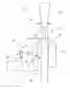
A device to inspect a longitudinal heat seal in tubular bag material. The seal is formed by a heated sealing bar (14). Downstream of the bar (14) is a heat sensing camera (20) that sends a signal to a central processing unit (21). The unit (21) will then identify any faults in the seal.
Assignee:
- TNA Australia Pty Limited 37 🇦🇺 Lidcombe, Australia
Applicant:
Interested in similar patents?
Get notified when new applications in this technology area are published.
Classification:
B31B50/006 » CPC further
Making rigid or semi-rigid containers, e.g. boxes or cartons Controlling; Regulating; Measuring; Improving safety
B31B70/006 » CPC further
Making flexible containers, e.g. envelopes or bags Controlling; Regulating; Measuring; Safety measures
B65B65/00 IPC
Details peculiar to packaging machines and not otherwise provided for; Arrangements of such details
G01M3/38 » CPC further
Investigating fluid-tightness of structures by using light
G01N25/72 » CPC main
Investigating or analyzing materials by the use of thermal means Investigating presence of flaws
B29C66/1122 » CPC further
General aspects of processes or apparatus for joining preformed parts; General aspects dealing with the joint area or with the area to be joined; Particular design of joint configurations particular design of the joint cross-sections; Joint cross-sections comprising a single joint-segment, i.e. one of the parts to be joined comprising a single joint-segment in the joint cross-section; Single lapped joints Single lap to lap joints, i.e. overlap joints
B29C66/4322 » CPC further
General aspects of processes or apparatus for joining preformed parts; General aspects of joining substantially flat articles, e.g. plates, sheets or web-like materials; Making flat seams in tubular or hollow articles; Joining single elements to substantially flat surfaces; Joining substantially flat articles ; Making flat seams in tubular or hollow articles; Joining a relatively small portion of the surface of said articles for making tubular articles or closed loops, e.g. by joining several sheets ; for making hollow articles or hollow preforms by joining a single sheet to itself
B29C66/49 » CPC further
General aspects of processes or apparatus for joining preformed parts; General aspects of joining substantially flat articles, e.g. plates, sheets or web-like materials; Making flat seams in tubular or hollow articles; Joining single elements to substantially flat surfaces Internally supporting the, e.g. tubular, article during joining
B29C66/8161 » CPC further
General aspects of processes or apparatus for joining preformed parts; General aspects of machine operations or constructions and parts thereof; General aspects of the pressing elements, i.e. the elements applying pressure on the parts to be joined in the area to be joined, e.g. the welding jaws or clamps characterised by the mounting of the pressing elements, e.g. of the welding jaws or clamps said pressing elements being supported or backed-up by springs or by resilient material
B29C66/8242 » CPC further
General aspects of processes or apparatus for joining preformed parts; General aspects of machine operations or constructions and parts thereof; Pressure application arrangements, e.g. transmission or actuating mechanisms for joining tools or clamps; Actuating mechanisms Pneumatic or hydraulic drives
B29C66/8322 » CPC further
General aspects of processes or apparatus for joining preformed parts; General aspects of machine operations or constructions and parts thereof characterised by the movement of the joining or pressing tools; Reciprocating joining or pressing tools Joining or pressing tools reciprocating along one axis
B29C66/849 » CPC further
General aspects of processes or apparatus for joining preformed parts; General aspects of machine operations or constructions and parts thereof; Specific machine types or machines suitable for specific applications Packaging machines
B29C66/872 » CPC further
General aspects of processes or apparatus for joining preformed parts; General aspects of machine operations or constructions and parts thereof; Auxiliary operations or devices Starting or stopping procedures
B29C66/91216 » CPC further
General aspects of processes or apparatus for joining preformed parts; Measuring or controlling the joining process by measuring or controlling the temperature, the heat or the thermal flux by measuring the temperature, the heat or the thermal flux by measuring the temperature with special temperature measurement means or methods enabling contactless temperature measurements, e.g. using a pyrometer
B29C65/18 » CPC further
Joining of preformed parts ; Apparatus therefor by heating, with or without pressure using heated tools
B29C66/91221 » CPC further
General aspects of processes or apparatus for joining preformed parts; Measuring or controlling the joining process by measuring or controlling the temperature, the heat or the thermal flux by measuring the temperature, the heat or the thermal flux by measuring the temperature of the parts to be joined
B29C66/91411 » CPC further
General aspects of processes or apparatus for joining preformed parts; Measuring or controlling the joining process by measuring or controlling the temperature, the heat or the thermal flux by controlling or regulating the temperature, the heat or the thermal flux by controlling or regulating the temperature of the parts to be joined, e.g. the joining process taking the temperature of the parts to be joined into account
B29C66/91431 » CPC further
General aspects of processes or apparatus for joining preformed parts; Measuring or controlling the joining process by measuring or controlling the temperature, the heat or the thermal flux by controlling or regulating the temperature, the heat or the thermal flux by controlling or regulating the temperature the temperature being kept constant over time
B29C66/961 » CPC further
General aspects of processes or apparatus for joining preformed parts; Measuring or controlling the joining process characterised by the method for implementing the controlling of the joining process involving a feedback loop mechanism, e.g. comparison with a desired value
B65B9/2028 » CPC further
Enclosing successive articles, or quantities of material, e.g. liquids or semiliquids, in flat, folded, or tubular webs of flexible sheet material; Subdividing filled flexible tubes to form packages; Enclosing successive articles, or quantities of material, in preformed tubular webs, or in webs formed into tubes around filling nozzles, e.g. extruded tubular webs the webs being formed into tubes around the filling nozzles; Tube advancing means Rollers or belts
B65B57/00 » CPC further
Automatic control, checking, warning, or safety devices
G01M3/002 » CPC further
Investigating fluid-tightness of structures by using thermal means
B65B51/26 » CPC further
Devices for, or methods of, sealing or securing package folds or closures; Devices for gathering or twisting wrappers, or necks of bags; Applying or generating heat or pressure or combinations thereof Devices specially adapted for producing transverse or longitudinal seams in webs or tubes
B65B51/00 IPC
Devices for, or methods of, sealing or securing package folds or closures; Devices for gathering or twisting wrappers, or necks of bags
G01M3/00 IPC
Investigating fluid-tightness of structures
B29C65/00 IPC
Joining of preformed parts ; Apparatus therefor
B65B9/20 IPC
Enclosing successive articles, or quantities of material, e.g. liquids or semiliquids, in flat, folded, or tubular webs of flexible sheet material; Subdividing filled flexible tubes to form packages; Enclosing successive articles, or quantities of material, in preformed tubular webs, or in webs formed into tubes around filling nozzles, e.g. extruded tubular webs the webs being formed into tubes around the filling nozzles
Description
TECHNICAL FIELD
The present invention relates to packaging machines that form bags of product, the bags being formed from tubular bag material that is longitudinally sealed and transversely cut and sealed to form the bags.
BACKGROUND OF THE INVENTION
Described in U.S. Pat. No. 4,663,917 is a packaging machine. The packaging machine receives tubular bag material to the interior of which product is delivered. The tubular bag material is formed from a web (strip) that via a former is transformed into the tubular configuration. The longitudinally extending edge portions of the web are joined so as to form a longitudinal seal. Product is delivered to the interior of the tubular bag material, with the packaging machine then transversely sealing are of cutting the tubular bag material, at longitudinally spaced locations, to form bags.
If the longitudinal and/or transverse seals are not properly formed, the product can degrade. Various means have been proposed for checking the integrity of the seals.
As an example, seal testing devices are described in U.S. Pat. Nos. 6,568,247, 6,202,476 and 6,041,646.
Previous methods of detecting improperly formed seals have a number of disadvantages including not successful detecting faulty seals, and being unduly complex and unreliable.
Object of the Invention
It is the object of the present invention to overcome or substantially ameliorate at least one of the above disadvantages.
SUMMARY OF THE INVENTION
There is disclosed herein a device to inspect a longitudinal heat seal in tubular bag material, the bag material being formed of plastics material having longitudinally extending and overlapping edge portions secured together by the heat seal, the device including:
a drive assembly to engage the tubular bag material to move the tubular bag material along a predetermined path in a predetermined direction;
a heat sealing mechanism to engage the longitudinally extending edge portions to heat the edge portions to form said longitudinally extending heat seal; and
a camera directed at the heat seal and to provide a signal indicative of the temperature of the heat seal exposed to the camera.
Preferably, said camera provides a signal indicative of infrared radiation emanating from the seal to thereby provide a signal indicative of the temperature of the seal exposed to the camera.
Preferably, the camera provides a signal indicative of any temperature gradient transversely across the seal.
There is further disclosed herein, in combination, the above device, and a heat sealing bar to engage the tubular bag material to form the seal, the bar being supported for movement between an engaging position to engage the bag material to form the seal, and a retracted position, spaced from the engaged position so as not to be engaged with the tubular bag material, and a drive assembly operatively associated with the bar to move the bar between the engaged and retracted positions, the drive assembly also generating a signal delivered to a central process unit to provide an indication of when the bar is engaged with the tubular bag material, with the camera also delivering the camera signal to the unit.
Preferably, the drive assembly includes a spring urging the bar to the engaged position, and a cylinder to move the bar from the engaged position to the retracted position.
BRIEF DESCRIPTION OF THE DRAWINGS
The preferred form of the present invention will now be described by way of example with reference to the accompanying drawing that schematically depicts in sectioned side elevation a device to inspect a longitudinally extending heat seal in tubular bag material to detect faults in the seal.
DETAILED DESCRIPTION OF THE PREFERRED EMBODIMENT
In the accompanying drawing there is schematically depicted a former 10 to which a web of packaging film is delivered. The web is in the form of a strip that engages the former surface 11 so as to be configured into a tubular configuration. Formers are and described in U.S. Pat. Nos. 7,124,559 and 7,415,809. The tubular bag material is driven in the direction 12 engaged with vacuum drive belts 13. The suitable vacuum belt assemblies are described in U.S. Pat. Nos. 4,910,943 and 7,472,528.
The packaging film has longitudinally extending edge portions that overlap when the bag material is in the tubular configuration. The overlapping longitudinally extending edge portions are engaged by a heated sealing bar 14. The heating bar 14 is electrically heated and heats the tubular bag material to cause the plastics material thereof to melt, bond and form a longitudinal seal.
Above the former 11 is a product delivery chute 15 to which batches of product are delivered so as to be located within the tubular bag material. A packaging machine downstream of the belts 13 strips the bag material, forms transverse seals and cuts individual bags of product from the tubular bag material. A suitable packaging machine is described in U.S. Pat. No. 4,663,917.
The bar 14 is mounted on a supporting frame for linear movement in the direction 16, that is a direction transverse of the direction 12, and a direction transverse relative to the tubular bag material and longitudinal seal. The bar 14 is movable between a position of engagement with the tubular bag material to form the seal, and a retracted position spaced from the tubular bag material.
A bar drive assembly 22 moves the bar 14 in the direction 16 and includes pneumatic or hydraulic cylinder 17 is attached to the bar 14, and a valve 18. Preferably, the cylinder 17 is pneumatically operated and receives air under pressure from the valve 18.
The bar 14 is urged to the engaged position by means of a spring 23. Actuation of the cylinder 17 by the valve 18 moves the bar 14 in the direction 16 to move the bar 14 to the retracted position.
Downstream of the bar 14 in the direction 12 is a heat sensing camera 20. The camera 20 is provided to generate a signal indicative of the temperature of the longitudinal seal in the tubular bag material. If there is a fault in the seal, then the area of the fault will be at a lower temperature. As a particular example, the camera 20 could detect infrared radiation coming from the seal in order to provide a signal indicative of the temperature of the seal. Preferably the camera 20 is also adapted to provide a signal indicative of the temperature gradient across the seal. If the temperature gradient across the seal is not consistent, then again this is indicative of a flaw in the seal.
The camera 20 sends a signal to a central processing unit 21. The processing unit 21 is operatively associated with the packaging machine below, as well as other apparatus such as the drive mechanism for the belts 13, to cease operations should a faulty seal be detected. In particular, the unit 21 could cease operation of the packaging machine and associated apparatus if the temperature of a portion of the seal is outside of the desired range, or the temperature gradient across the seal is not consistent. The unit 21 also controls the valve 18 and therefore is aware of the position of the bar 14 and therefore will not expect a desired temperature of the seal to be detected when the bar 14 is in the retracted position.
Claims
1. A device to inspect a longitudinal heat seal in tubular bag material, the bag material being formed of plastics material having longitudinally extending and overlapping edge portions secured together by the heat seal, the device including:
a drive assembly to engage the tubular bag material to move the tubular bag material along a predetermined path in a predetermined direction;
a heat sealing mechanism to engage the longitudinally extending edge portions to heat the edge portions to form said longitudinally extending heat seal; and
a camera directed at the heat seal and to provide a signal indicative of the temperature of the heat seal exposed to the camera.
2. The device of claim I, wherein said camera provides a signal indicative of infrared radiation emanating from the seal to thereby provide a signal indicative of the temperature of the seal exposed to the camera.
3. The device of claim 1, wherein the camera provides a signal indicative of any temperature gradient transversely across the seal.
4. In combination, the device of claim 1, and a heat sealing bar to engage the tubular bag material to form the seal, the bar being supported for movement between an engaging position to engage the bag material to form the seal, and a retracted position, spaced from the engaged position so as not to be engaged with the tubular bag material, and a drive assembly operatively associated with the bar to move the bar between the engaged and retracted positions, the drive assembly also generating a signal delivered to a central process unit to provide an indication of when the bar is engaged with the tubular bag material, with the camera also delivering the camera signal to the unit.
5. The combination of claim 4, wherein the drive assembly includes a spring urging the bar to the engaged position, and a cylinder to move the bar from the engaged position to the retracted position.
6. The device of claim 2, wherein the camera provides a signal indicative of any temperature gradient transversely across the seal.
7. In combination, the device of claim 1, and a heat sealing bar to engage the tubular bag material to form the seal, the bar being supported for movement between an engaging position to engage the bag material to form the seal, and a retracted position, spaced from the engaged position so as not to be engaged with the tubular bag material, and a drive assembly operatively associated with the bar to move the bar between the engaged and retracted positions, the drive assembly also generating a signal delivered to a central process unit to provide an indication of when the bar is engaged with the tubular bag material, with the camera also delivering the camera signal to the unit.
8. The combination of claim 7, wherein the drive assembly includes a spring urging the bar to the engaged position, and a cylinder to move the bar from the engaged position to the retracted position.
9. In combination, the device of claim 3, and a heat sealing bar to engage the tubular bag material to form the seal, the bar being supported for movement between an engaging position to engage the bag material to form the seal, and a retracted position, spaced from the engaged position so as not to be engaged with the tubular bag material, and a drive assembly operatively associated with the bar to move the bar between the engaged and retracted positions, the drive assembly also generating a signal delivered to a central process unit to provide an indication of when the bar is engaged with the tubular bag material, with the camera also delivering the camera signal to the unit.
10. The combination of claim 9, wherein the drive assembly includes a spring urging the bar to the engaged position, and a cylinder to move the bar from the engaged position to the retracted position.
Images & Drawings included:

Sources:
- United States Patent and Trademark Office - verify current appl. status at the USPTO↗
Recent applications in this class:
- » 20250271375 2025-08-28
AIRCRAFT FUEL TANK FASTENER INSPECTION - » 20250271374 2025-08-28
IN-SITU VARIABLE TEMPERATURE BOW METROLOGY - » 20250244272 2025-07-31
METHOD FOR DETECTING SURFACE DEFECT OF THERMAL CUP, SYSTEM THEREOF, DEVICE AND MEDIUM - » 20250189472 2025-06-12
DEVICE FOR DETECTING SWITCH DAMAGE USING TEMPERATURE SENSING AND METHOD OF OPERATING THE SAME - » 20250155394 2025-05-15
DETERIORATION DISCRIMINATING DEVICE AND DETERIORATION DISCRIMINATING METHOD - » 20250146964 2025-05-08
THERMAL IMAGING METHOD FOR CRACK AND HOLE DETECTION IN SEMICONDUCTOR DEVICES - » 20250137954 2025-05-01
System and Method for Inspection of Low Emissivity Surfaces Using a Pulsed Light Emitting Diode Heat Source for Thermal Nondestructive Evaluation - » 20250130188 2025-04-24
IMAGE ACQUISITION APPARATUS, INSPECTION APPARATUS, AND IMAGE ACQUISITION METHOD - » 20250076232 2025-03-06
Inspection Apparatus and Mounting Base - » 20250076231 2025-03-06
MONITORING DEVICE
Recent applications for this Assignee:
- » 20200391895 2020-12-17
Assembly for forming bags - » 20200015494 2020-01-16
Die for a confectionery moulding machine - » 20190331548 2019-10-31
Bag engaging device - » 20190300217 2019-10-03
Packaging machine - » 20180086487 2018-03-29
Former chute - » 20170127882 2017-05-11
Fryer - » 20170057749 2017-03-02
Slip conveyor - » 20160318720 2016-11-03
Bag stacker - » 20140028309 2014-01-30
Metal detector - » 20130337988 2013-12-19
PACKAGING MACHINE FOR BLOCK BOTTOM BAGS