System for machining a bevel
US20120329372A1
2012-12-27
13/529,348
2012-06-21
✅ Patent granted
US 8,956,202 B2
2015-02-17
-
-
George Nguyen
Oblon, Spivak, McClelland, Maier & Neustadt, L.L.P.
2033-02-06
Abstract:
The invention relates to a system (1) for machining a bevel (32, 34) on a disk shaped part (31) including a grinding device (3) having abrasive means (4), a device (5) for securing the part (31) including a support (13) to which said part is fitted and which is integral with an axis of rotation (16). According to the invention, the securing device (5) further includes a means (15) of orienting the axis (16) of rotation (B) to define the angle of said one bevel (32, 34) and a means (17) of moving the support (13) closer to the abrasive means (4) in order to machining the part (13) under stress.
The invention concerns the field of crystals for timepieces.
Inventors:
- Jean-Paul Tassetti 3 🇫🇷 Orchamps-Vennes, France
- Christophe Vuillemin 1 🇫🇷 Le Belieu, France
- Fabien Bez 1 🇫🇷 Montlebon, France
Assignee:
- COMADUR S.A. 75 🇨🇭 Le Locle, Switzerland
Applicant:
Interested in similar patents?
Get notified when new applications in this technology area are published.
Classification:
B24B13/00 IPC
Machines or devices designed for grinding or polishing optical surfaces on lenses or surfaces of similar shape on other work; Accessories therefor
B24B9/085 » CPC main
Machines or devices designed for grinding edges or bevels on work or for removing burrs; Accessories therefor characterised by a special design with respect to properties of materials specific to articles to be ground of non-metallic inorganic material, e.g. stone, ceramics, porcelain of glass for watch glasses
B24B21/002 » CPC further
Machines or devices using grinding or polishing belts ; Accessories therefor for grinding edges or bevels
G04D3/065 » CPC further
Watchmakers' or watch-repairers' machines or tools for working materials; Devices for shaping or setting watch glasses Shaping by removing material, e.g. cutting out from a plate, milling the edges
B24B9/00 IPC
Machines or devices designed for grinding edges or bevels on work or for removing burrs; Accessories therefor
B24B9/08 IPC
Machines or devices designed for grinding edges or bevels on work or for removing burrs; Accessories therefor characterised by a special design with respect to properties of materials specific to articles to be ground of non-metallic inorganic material, e.g. stone, ceramics, porcelain of glass
B24B21/00 IPC
Machines or devices using grinding or polishing belts ; Accessories therefor
G04D3/06 IPC
Watchmakers' or watch-repairers' machines or tools for working materials Devices for shaping or setting watch glasses
Description
This application claims priority from European Patent Application No. 11171314.5 filed Jun. 24, 2011, the entire disclosure of which is incorporated herein by reference.
FIELD OF THE INVENTION
The invention relates to a lapidary system for a part made of hard material such as corundum and, more specifically, a system of this kind for forming a bevel.
BACKGROUND OF THE INVENTION
Watch crystal bevels are generally formed by a grinding wheel which moves tangentially at the bevel angle against the edge of the part to be cut. This technique is widely used but is slow to perform, regularly causes chips (slivers of material) and requires subsequent brushing.
SUMMARY OF THE INVENTION
It is an object of the present invention to overcome all or part of the aforementioned drawbacks, by proposing a system for machining a bevel which speeds up manufacture and which reduces the discard rate.
The invention therefore relates to a system for machining a bevel on a disk shaped part including a grinding device comprising abrasive means, a device for securing the part comprising a support onto which said part is fitted and which is integral with an axis of rotation, characterized in that the securing device further includes a means of orienting the axis of rotation to define the angle of said bevel and a means of moving the support closer to the abrasive means in order to machine the part under stress.
Thus, advantageously, the bevel angle of the part is directly given by the inclination of the part relative to the abrasive means, and the stress caused by the support moving means enables bevelling to be performed more quickly and prevents the material from undergoing excessive stress, while rendering any subsequent step of brushing the bevel unnecessary.
In accordance with other advantageous features of the invention:
-
- the abrasive means is moveable so as to improve machining;
- the abrasive means is formed by a rotatably mounted abrasive strip;
- underneath the area of contact between the abrasive strip and the part, the grinding device includes a resilient means for maintaining the contact between the abrasive strip and the part;
- the elastic means is formed by an elastomer block;
- the means of moving the support closer includes a vertical slide for moving the support vertically relative to the abrasive means;
- the orientating means includes a worm-toothed wheel assembly for shifting the inclination of the axis of rotation of the support relative to the means of moving the support closer;
- the securing device includes a horizontal slide for moving the support transversely relative to the abrasive means;
- the horizontal slide is moved via a connecting rod-crank assembly in order to move the support relative to the abrasive means in a to-and-fro motion;
- the disk shaped part is a spherical crystal.
BRIEF DESCRIPTION OF THE DRAWINGS
Other features and advantages will appear clearly from the following description, given by way of non-limiting illustration, with reference to the annexed drawings, in which:
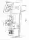
FIG. 1 is a perspective elevation of a system according to the invention;
FIG. 2 is a perspective side view of a system according to the invention;
FIG. 3 is an enlarged view of one part of FIG. 1;
FIG. 4 is a perspective view of a part obtained by the system according to the invention;
FIG. 5 is a partial cross-section of the part illustrated in FIG. 4.
DETAILED DESCRIPTION OF PREFERRED EMBODIMENTS
As illustrated in FIG. 1, the invention relates to a system 1 for machining a bevel 32, 34 for a disk shaped part 31 made of hard material such as corundum. According to the invention, part 31 may be intended to form a spherical timepiece crystal.
Machining system 1 includes a grinding device 3, a device 5 for securing the part and a control device 7 for controlling the actuators of system 1. All of the devices are mounted on a frame 2.
According to the invention, grinding device 3 includes an abrasive means 4 which is preferably moveable so as to improve machining. As visible in FIG. 2, abrasive means 4 is formed by an abrasive strip 6 rotatably mounted on two rollers 8, 10 and driven by an actuator 12 in motion A. As visible in FIGS. 1 to 3, grinding device 3 includes a restricted area 14 in which abrasive means 4 is accessible and protected by vertical walls to limit blasting of material and to safeguard operations.
Advantageously according to the invention, underneath the area 14 of contact between abrasive strip 6 and part 31 to be machined, grinding device 3 further includes a resilient means 9 for maintaining the contact between abrasive strip 6 and said part. Thus, preferably, resilient means 9 is formed by a block 11 made of elastomer, such as rubber, several centimetres thick and covering all or part of restricted area 14 underneath abrasive means 4.
According to the invention, securing device 5 of part 31 includes a support 13 to which part 31 to be machined is fitted and which is integral with an axis of rotation 16 driven by an actuator 18 in motion B. Advantageously according to the invention, securing device 5 further includes a means 15 of orienting the axis of rotation 16 to define the angle β, γ of bevel 32, 34 and a means 17 for moving support 13 closer to abrasive means 4 in order to machine part 31 under stress.
Preferably according to the invention, means 17 for moving the support closer includes a vertical slide 19 for moving support 13 vertically in direction C relative to abrasive means 4. Indeed, it was found that the combination of the stress caused by means 17 and the compensation performed by resilient means 9 to maintain the contact between abrasive strip 6 and the part 31 for machining enabled bevels 32, 34 to be formed without the material undergoing excessive stresses, resulting in a low discard rate and the omission of an additional step of brushing bevel 32, 34.
According to the invention orienting means 15 preferably includes a worm-toothed wheel assembly 20 for shifting the inclination α of axis of rotation 16 of support 13 relative to means 17 for moving support 13 closer. Thus, advantageously, the bevel angle β, γ of part 31 is directly given by the inclination α of part 31 relative to abrasive means 4.
Finally, securing device 5 preferably includes a horizontal slide 21 for moving support 13 transversely in direction D relative to abrasive means 4. As visible in FIGS. 1 to 3, horizontal slide 21 is used as a base for securing device 5 onto frame 2. Thus, via a set square shaped member 22, horizontal slide 21 carries vertical slide 19, which in turn carries orienting means 15 and the support 13—axis of rotation 16—actuator 18 assembly.
Advantageously according to the invention, horizontal slide 21 is moved via a connecting rod-crank assembly 23 in order to move support 13 transversely in direction D relative to abrasive means 4 in a to-and-for motion. As visible in FIGS. 1 to 3, the connecting rod-crank assembly 23 is connected to horizontal slide 21 on set square shaped member 22.
An example part 31 modified by machining system 1 is illustrated in FIGS. 4 and 5. Part 31 includes a substantially disk shaped body 33 whose edges have bevels 32, 34 at predefined angles β, γ. As visible in FIG. 5, part 31 is a spherical crystal, i.e. the difference in dimension between the external radius 35 and an internal radius 36 thereof is the constant thickness e.
Of course, this invention is not limited to the illustrated example but is capable of various variants and alterations that will appear to those skilled in the art. In particular, the shape of part 31 may be different and/or made of a different material from corundum and/or for an application other than a timepiece.
Claims
What is claimed is:1. A system for machining a bevel on a watch crystal including a grinding device having an abrasive means, a device for securing the part including a support onto which said part is fitted and which is integral with an axis of rotation, the securing device further including a means of orienting the axis of rotation to define the angle of said one bevel and a means of moving the support closer to the abrasive means, so as to machine the part under stress, wherein, underneath the area of contact between the abrasive strip and the part, the grinding device includes a resilient means for maintaining the contact between the abrasive strip and the part.
2. The system according to claim 1, wherein the abrasive means is moveable in order to improve machining.
3. The system according to claim 2, wherein the abrasive means is formed by an abrasive strip which is rotatably mounted.
4. The system according to claim 1, wherein the resilient means is formed by an elastomer block.
5. The system according to claim 1, wherein the means for moving the support closer includes a vertical slide for moving the support vertically relative to the abrasive means.
6. The system according to claim 1, wherein the orienting means includes a worm-toothed wheel assembly for shifting the inclination of the axis of rotation of the support relative to the means for moving said support closer.
7. The system according to claim 1, wherein the securing device includes a horizontal slide for moving the support transversely relative to the abrasive means.
8. The system according to claim 1, wherein the horizontal slide is moved via a connecting rod-crank assembly in order to move the support in a to-and-for motion relative to the abrasive means.
9. The system according to claim 1, wherein the crystal is a spherical crystal.
Images & Drawings included:


Sources:
- United States Patent and Trademark Office - verify current appl. status at the USPTO↗
Similar patent applications:
Recent applications for this Assignee:
- » 20250155848 2025-05-15
WATERTIGHT WATCH CASE - » 20250154679 2025-05-15
METHOD FOR MANUFACTURING SAPPHIRE BARS - » 20250066266 2025-02-27
METHOD FOR THE THREE-DIMENSIONAL DECORATION OF A SUBSTRATE TO PRODUCE AN EXTERNAL PART - » 20250066262 2025-02-27
METHOD FOR THE THREE-DIMENSIONAL DECORATION OF A SUBSTRATE TO PRODUCE AN EXTERNAL PART - » 20240402649 2024-12-05
MULTICOLOUR CERMET AND/OR CERAMIC ARTICLE AND MANUFACTURING METHOD THEREOF - » 20240342811 2024-10-17
METHOD FOR MANUFACTURING A CUTTING TOOL WITH LUBRICATION ORIFICES OF COMPLEX SHAPES AND CUTTING TOOL WITH LUBRICATION ORIFICES OF COMPLEX SHAPES - » 20240099433 2024-03-28
METHOD FOR MANUFACTURING AN EXTERNAL COMPONENT OF A WATCH, OF A FASHION ITEM OR OF A JEWELLERY ITEM - » 20240091882 2024-03-21
METHOD FOR MANUFACTURING AN EXTERNAL COMPONENT INCLUDING A DIFFRACTION GRATING - » 20240074553 2024-03-07
PROCESS FOR PRODUCING A HOROLOGICAL OR JEWELLERY ELEMENT INLAID WITH A CERAMIC DECORATION - » 20240000201 2024-01-04
Wristlet with links made of a hard material