Method and device for testing the tightness of an electric machine stator core
US20130047748A1
2013-02-28
13/662,265
2012-10-26
✅ Patent granted
US 9,148,045 B2
2015-09-29
-
-
Lisa Caputo | Jonathan Dunlap
Buchanan Ingersoll & Rooney PC
2032-10-26
Abstract:
A method is provided for testing the tightness of an electric machine stator core includes: introducing a test instrument that is connected to a movable support into an air gap between a stator core and a rotor, locally placing the test instrument and locally testing defined zones of the generator stator core. A device for carrying out the method is also provided.
Inventors:
- ALSTOM TECHNOLOGY LTD 50 🇨🇭 Baden, Switzerland
- Massimiliano Visintin 12 🇨🇭 Zurich, Switzerland
Assignee:
- ALSTOM TECHNOLOGY LTD 1,730 🇨🇭 Baden, Switzerland
Applicant:
Interested in similar patents?
Get notified when new applications in this technology area are published.
Classification:
G01L1/00 IPC
Measuring force or stress, in general
G01B7/14 IPC
Measuring arrangements characterised by the use of electric or magnetic means for measuring distance or clearance between spaced objects or spaced apertures
G01B17/02 » CPC further
Measuring arrangements characterised by the use of subsonic, sonic or ultrasonic vibrations for measuring thickness
G01B7/04 » CPC further
Measuring arrangements characterised by the use of electric or magnetic means for measuring length, width or thickness specially adapted for measuring length or width of objects while moving
G01R31/343 » CPC further
Arrangements for testing electric properties; Arrangements for locating electric faults; Arrangements for electrical testing characterised by what is being tested not provided for elsewhere; Testing dynamo-electric machines in operation
H02K2201/03 » CPC further
Specific aspects not provided for in the other groups of this subclass relating to the magnetic circuits Machines characterised by aspects of the air-gap between rotor and stator
G01N2203/0039 » CPC further
Investigating strength properties of solid materials by application of mechanical stress; Generation of the force using mechanical means Hammer or pendulum
G01M7/08 » CPC further
Vibration-testing of structures; Shock-testing of structures Shock-testing
G01B7/16 » CPC further
Measuring arrangements characterised by the use of electric or magnetic means for measuring the deformation in a solid, e.g. by resistance strain gauge
G01B7/144 » CPC further
Measuring arrangements characterised by the use of electric or magnetic means for measuring distance or clearance between spaced objects or spaced apertures Measuring play on bearings
G01R31/34 » CPC further
Arrangements for testing electric properties; Arrangements for locating electric faults; Arrangements for electrical testing characterised by what is being tested not provided for elsewhere Testing dynamo-electric machines
G01N2203/0617 » CPC further
Investigating strength properties of solid materials by application of mechanical stress; Details not specific for a particular testing method; Indicating or recording means; Sensing means Electrical or magnetic indicating, recording or sensing means
G01N2203/0658 » CPC further
Investigating strength properties of solid materials by application of mechanical stress; Details not specific for a particular testing method; Indicating or recording means; Sensing means using acoustic or ultrasonic detectors
H02K15/02 » CPC further
Methods or apparatus specially adapted for manufacturing, assembling, maintaining or repairing of dynamo-electric machines of stator or rotor bodies
G01N29/265 » CPC further
Investigating or analysing materials by the use of ultrasonic, sonic or infrasonic waves; Visualisation of the interior of objects by transmitting ultrasonic or sonic waves through the object; Details, e.g. general constructional or apparatus details; Arrangements for orientation or scanning by relative movement of the head and the sensor by moving the sensor relative to a stationary material
G01N3/00 IPC
Investigating strength properties of solid materials by application of mechanical stress
G01M7/00 » CPC further
Vibration-testing of structures; Shock-testing of structures
H02K15/00 » CPC main
Methods or apparatus specially adapted for manufacturing, assembling, maintaining or repairing of dynamo-electric machines
Description
INCORPORATION BY REFERENCE
The following documents are incorporated herein by reference as if fully set forth: International Patent Application No. PCT/EP2011/056193, filed Apr. 19, 2011—and—European Patent Application No. 10161391.7, filed Apr. 29, 2010.
TECHNICAL FIELD
The present invention relates to method and a device for testing the tightness of an electric machine stator core.
BACKGROUND OF THE INVENTION
Electric machines are generally known to comprise an annular stator and an internal rotor, however different topologies have been already adopted and are actually manufactured.
The stator comprises an iron core provided with slots housing the stator winding. The stator core is made of packets of electrically insulated iron sheets, joined together by thin spacers, which define the cooling channels between the packets for the relevant cooling gas flow.
All stator packets and the spacers are tightened together under pressure by means of press plates at both core ends and additional key bars, generally welded to the core back and to both press plates.
During operation, the stator core can loose its tightness, due to electromagnetic, mechanical and thermal stresses and aging. In particular the iron sheets can start to separate from each other and to vibrate, finally leading to localized hot spots due to short circuits of the sheets and/or to breakdown in the stator winding, i.e. to electric machine failures.
In addition, in case an upgrade (to increase its rated power) or a rewind of the electric machine is foreseen, the stator core conditions must be checked to assess whether it is capable of withstanding the new operating conditions or respectively bearing the expected lifetime extension. The tightness of the stator core is one of the required assessments of the electric machine conditions, which are to be performed before any renewal.
Traditionally, in order to test the stator core tightness, the rotor must be extracted so as to allow enough space within the stator to perform the required tests.
However, rotor extraction is very time consuming and both rewinds and upgrades have strict time constraints for the full implementation. In addition, rotor extraction creates a risk of stator and/or rotor damage.
SUMMARY OF THE INVENTION
The present disclosure is directed to a method for testing the tightness of an electric machine stator core. The electric machine has a stator core and a rotor defining an air gap therebetween. The method includes introducing a test instrument that is connected to a movable support into the air gap, locally placing the test instrument and locally testing defined zones of the generator stator core.
The present disclosure is also directed to a device for testing the tightness of an electric machine stator core, including a movable support, insertable in an air gap between an electric generator stator core and a rotor. The device also includes a test instrument carried by the movable support and locally positionable to locally test defined zones of the generator stator core.
BRIEF DESCRIPTION OF THE DRAWINGS
Further characteristics and advantages of the invention will be more clear from the description of a preferred but non-exclusive embodiment of the method and device, illustrated by way of non-limiting example in the accompanying drawings, in which:
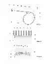
FIG. 1 is a schematic view of a device associated to a stator core and rotor (in dashed lines) of an electric machine such as an electric generator;
FIGS. 2 and 3 show a particular of a first embodiment of the invention; and
FIGS. 4 through 6 show further embodiments of the invention.
DETAILED DESCRIPTION OF EMBODIMENTS OF THE INVENTION
Introduction to the Embodiments
The technical aim of the present invention is therefore to provide a method and a device by which the said problems of the known art are eliminated.
Within the scope of this technical aim, an aspect of the invention is to provide a method and a device that permit tests for ascertaining the tightness of the stator core to be carried out without the need of rotor extraction.
Another aspect of the invention is to provide a method and a device that allow tests to be carried out in an easy and fast manner.
A further aspect of the invention is to provide a method and a device that reduce the risks that the stator core and/or the rotor are damaged because of the tightness tests.
The technical aim, together with these and further aspects, are attained according to the invention by providing a method and a device in accordance with the accompanying claims.
DETAILED DESCRIPTION
With reference to the figures, reference number 1 generally indicates an electric machine such as an electric generator having a stator core 2 and a rotor 3.
The stator core 2 is made of a plurality of packets 4 of iron sheets 5 that are spaced apart by means of ventilation spacers (such as ribs, not shown) to determine the stator core cooling channels 6.
The device for testing the tightness of the stator core 2 comprises a movable support 10, which can be introduced into the air gap 11 between the stator core 2 and the rotor 3.
The support 10 carries a test instrument 12 to locally place it within the gap 11 and locally test defined zones of the generator stator core 2.
Preferably, the support 10 is arranged to place the test instruments 12 over at least half of the air gap axial length (i.e. the length of the air gap 11 along the longitudinal axis 13 of the electric machine such as generator).
In particular, the support 10 may be able to place the test instrument 12 over the whole air gap axial length, such that it is possible to test the whole stator core 2 by mounting the device 1 only once, or over half the gap axial length, such that it is possible to test the whole stator core by mounting the device 1 twice (i.e. at both stator core ends).
The support 10 comprises a guide 15 that can be circumferentially connected to the electric machine such as generator 1 along the air gap 11 (for example it can be connected to the retaining ring of the generator); preferably the guide 15 extends over the whole air gap circumferential length, such that the whole stator core 2 may be tested by mounting the device 1 only once, it is anyhow possible that in different embodiments the guide 15 circumferentially extends over only a part of the air gap 11.
The guide 15 carries a cart 16, movable along it to reach different circumferential positions of the stator core 2.
The cart 16 carries an extendable arm 17 that carries the test instrument 12.
In addition, the extendable arm may be provided with wheels 18 to guarantee a secure connection to the stator core 2 and/or rotor 3 during test operations.
In the following, particular embodiments of the invention with different test instruments are described.
FIGS. 2 and 3 show an embodiment in which the test instrument 12 comprises a mechanical sensor.
As shown in FIGS. 2 and 3, the arm 17 has a detecting head 20 that has hinged a mechanical sensor such as an elliptical plate 21 that can rotate, around an axis G, between an inserting position (as shown in FIGS. 2 and 3) and a testing position, rotated as indicated by arrow F.
Testing with this mechanical sensor is achieved by placing the plate 21 in the zone of the stator core 2 to be tested, and then making the plate 21 rotate as indicated by the arrow F; the force to be applied to the plate 21 to make it enter into a packet 4 between the iron sheets 5 is proportional to the remaining stiffness of the packet 4 to be measured.
FIGS. 4 and 5 show two different embodiments in which the testing instrument comprises an electric sensor.
In these embodiments a detecting head 20 connected to the arm 17 carries a sensor such as a coil 23 arranged to inject a high frequency magnetic flux into a packet 4, so as to induce a proper vibration of it.
A signal generated by the vibrating packet may be detected using the same coil 23 (as shown in FIG. 4), or using a different sensor 24 (as shown in FIG. 5).
In particular, the sensor 24 may be an electric sensor, such as a second coil, or an acoustic sensor, such as a microphone, or a mechanical sensor, such as an accelerometer to be placed onto the packet 4 under testing (for example in this case the sensor 24 may be supported by an auxiliary arm movable towards the stator core and vice versa).
Alternatively, the sensor 23 may be an acoustic sensor that generates an acoustic signal that makes the packet 4 vibrate and also detects the signal generated by the vibrating packet.
In addition, in this case a second sensor 24 may also be provided and, as already described; it may be an electric sensor such as a coil, an acoustic sensor such as a microphone or a mechanical sensor such as an accelerometer to be placed on the packet 4 to be tested.
FIG. 6 represents another embodiment, wherein the test instrument 12 comprises a mechanical sensor.
In this embodiment a detecting head 20 connected to the arm 17 carries an electric driven mechanical device such as a hammer 25 (micro-hammer), which hits the packet 4 so as to make it vibrate. The signal generated by the vibrating packet can be detected by another sensor 26. In particular the sensor 26 may be a mechanical sensor such as an accelerometer or an acoustic sensor such as a microphone.
Combination of the embodiments shown in FIGS. 2 through 6 is also possible.
The method for testing the tightness of an electric machine stator core with the rotor 3 inserted in the stator core 2 comprises:
-
- introducing the test instrument 12 that is connected to a movable support 10 into the air gap 11 between the stator core 2 and the rotor 3,
- locally placing the test instrument 12, i.e. placing the test instrument 12 in correspondence of the zone of the stator core 2 to be tested. This can be done by regulating the axial and circumferential position of the test instrument 12 within the gap 11;
- locally testing defined zones of the generator stator core 2.
Since testing is carried out on defined zones of the stator core 2 and since the testing instrument 12 may be brought in correspondence of any zone of the stator core 2, it is possible to test only the packets 4 that are more subject to become loose.
In addition, since tests are carried out locally, the exact position of the loose packets 4 is automatically known (because it is known the axial and the circumferential position where the tests are carried out).
Advantageously, tests are repeated a number of times at different axial and/or angular positions.
In different embodiments, tests are carried out by introducing the plate 21 between the stator core iron sheets 5, or by stressing the stator core iron sheets 5 to make them vibrate and detecting the vibrations. Preferably vibrations are detected by measuring a signal generated by the vibrating iron sheets 5.
Naturally the features described may be independently provided from one another.
In practice the materials used and the dimensions can be chosen at will according to requirements and to the state of the art.
It is understood, therefore, that this invention is not limited to the particular embodiments disclosed, but is intended to cover all modifications which are within the spirit and scope of the invention as defined by the appended claims; the above description; and/or shown in the attached drawings.
REFERENCE NUMBERS
- 1 electric machine (electric generator)
- 2 stator core
- 3 rotor
- 4 packets of 5
- 5 iron sheets
- 6 cooling channels
- 10 support
- 11 air gap
- 12 test instrument
- 13 longitudinal axis of 1
- 15 guide
- 16 cart
- 17 extendable arm
- 18 wheels
- 20 detecting head
- 21 plate
- 23 sensor
- 24 sensor
- 25 micro-hammer
- 26 sensor
- F arrow
- G rotation axis
Claims
What is claimed is:1. Method for testing the tightness of an electric machine stator core, wherein the electric machine comprises a stator core and a rotor defining an air gap therebetween, the method comprising introducing a test instrument that is connected to a movable support into the air gap, locally placing the test instrument and locally testing defined zones of the generator stator core.
2. The method as claimed in claim 1, wherein tests are repeated a number of times at different axial and/or angular positions.
3. The method as claimed in claim 1, further comprising introducing a plate between the stator core iron sheets.
4. The method as claimed in claim 1, further comprising stressing the stator core iron sheets to make them vibrate and detecting the vibrations.
5. The method as claimed in claim 4, wherein vibrations are detected by detecting a signal generated by the vibrating stator core iron sheets.
6. Device, for testing the tightness of an electric machine stator core, comprising a movable support, insertable in an air gap between an electric generator stator core and a rotor, and a test instrument carried by the movable support and locally positionable to locally test defined zones of the generator stator core.
7. The device as claimed in claim 6, wherein said support is arranged to place the test instrument over at least half of an axial length of the gap.
8. The device as claimed in claim 7, wherein said support comprises a guide, circumferentially connectable to the generator along at least a portion of its gap, a cart movable along the guide, and an arm that is connected to the cart and carries the test instrument.
9. The device as claimed in claim 8, wherein said arm is an extendable arm.
Images & Drawings included:


Sources:
- United States Patent and Trademark Office - verify current appl. status at the USPTO↗
Recent applications in this class:
- » 20130140920 2013-06-06
Stator assembly structure for axial flux electric machine - » 20130049522 2013-02-28
Retaining ring configuration system
Recent applications for this Assignee:
- » 20180020560 2018-01-18
ASSEMBLY OF MODULES, MODULE SUPPORT AND MODULE - » 20170341339 2017-11-30
METHOD FOR OBTAINING A CONFIGURATION FOR JOINING A CERAMIC MATERIAL TO A METALLIC STRUCTURE - » 20170316904 2017-11-02
Medium- or high-voltage circuit breaker or isolator, provided with improved fixed contacts, and method of use - » 20170284378 2017-10-05
Method for operating a solar thermal power system with an economizer recirculation line - » 20170213674 2017-07-27
Circuit breaker comprising an insulating hollow tube - » 20170023243 2017-01-26
Coal rope distributor with replaceable wear components - » 20160373236 2016-12-22
Electrical power networks - » 20160373022 2016-12-22
Balancing and/or discharge resistor arrangements - » 20160352239 2016-12-01
POWER ELECTRONIC CONVERTER - » 20160298844 2016-10-13
BURNER ARRANGEMENT INCLUDING AN AIR SUPPLY WITH TWO FLOW PASSAGES