METHOD AND SYSTEM FOR NAVIGATING AND SELECTING OBJECTS WITHIN A THREE-DIMENSIONAL VIDEO IMAGE
US20130050414A1
2013-02-28
13/216,940
2011-08-24
Abstract:
A method and system are provided for navigating and selecting objects within a 3D video image by computing a depth coordinate based upon two-dimensional (2D) image information from left and right views of such objects. In accordance with preferred embodiments, commonly available computer navigation devices and input devices can be used to achieve such navigation and object selection.
Inventors:
- Philip L. Swan 11 🇨🇦 Richmond Hill, Canada
- Pavel Siniavine 1 🇨🇦 Ricmond Hill, Canada
- Jitesh Arora 9 🇨🇦 Markham, Canada
- Alexander Zorin 3 🇨🇦 Aurora, Canada
- Gabor Sines 15 🇨🇦 Toronto, Canada
- Xingping Cao 4 🇨🇦 Markham, Canada
- Mohamed K. Cherif 1 🇨🇦 Thornhill, Canada
- Edward Callway 3 🇨🇦 Toronto, Canada
Assignee:
- ATI TECHNOLOGIES ULC 916 🇨🇦 Markham, Canada
Interested in similar patents?
Get notified when new applications in this technology area are published.
Classification:
G02B30/24 » CPC main
Optical systems or apparatus for producing three-dimensional [3D] effects, e.g. stereoscopic images by providing first and second parallax images to an observer's left and right eyes of the stereoscopic type involving temporal multiplexing, e.g. using sequentially activated left and right shutters
G06F3/011 » CPC further
Input arrangements for transferring data to be processed into a form capable of being handled by the computer; Output arrangements for transferring data from processing unit to output unit, e.g. interface arrangements; Input arrangements or combined input and output arrangements for interaction between user and computer Arrangements for interaction with the human body, e.g. for user immersion in virtual reality
G06F3/0304 » CPC further
Input arrangements for transferring data to be processed into a form capable of being handled by the computer; Output arrangements for transferring data from processing unit to output unit, e.g. interface arrangements; Input arrangements or combined input and output arrangements for interaction between user and computer; Arrangements for converting the position or the displacement of a member into a coded form Detection arrangements using opto-electronic means
G06F3/04815 » CPC further
Input arrangements for transferring data to be processed into a form capable of being handled by the computer; Output arrangements for transferring data from processing unit to output unit, e.g. interface arrangements; Input arrangements or combined input and output arrangements for interaction between user and computer; Interaction techniques based on graphical user interfaces [GUI] based on specific properties of the displayed interaction object or a metaphor-based environment, e.g. interaction with desktop elements like windows or icons, or assisted by a cursor's changing behaviour or appearance Interaction with a metaphor-based environment or interaction object displayed as three-dimensional, e.g. changing the user viewpoint with respect to the environment or object
H04N13/239 » CPC further
Stereoscopic video systems; Multi-view video systems; Details thereof; Image signal generators using stereoscopic image cameras using two 2D image sensors having a relative position equal to or related to the interocular distance
H04N13/341 » CPC further
Stereoscopic video systems; Multi-view video systems; Details thereof; Image reproducers; Displays for viewing with the aid of special glasses or head-mounted displays [HMD] using temporal multiplexing
H04N2013/0081 » CPC further
Stereoscopic video systems; Multi-view video systems; Details thereof; Stereoscopic image analysis Depth or disparity estimation from stereoscopic image signals
H04N13/00 IPC
Stereoscopic video systems; Multi-view video systems; Details thereof
Description
BACKGROUND
The present disclosure relates to three-dimensional (3D) video images, and in particular, to navigating and selecting objects within such images.
As use of 3D video images increases, particularly within video games, the need for an effective way to navigate within such images becomes greater. This can be particularly true for applications other than gaming, such as post-production processing of video used in the creation of 3D movies and television shows. However, translating the movements of a typical computer navigation device, such as a computer mouse, into the 3D space of a 3D video image has proven to be difficult. Accordingly, it would be desirable to have a system and method by which commonly available computer navigation devices can be used to navigate and select objects within a 3D video image.
SUMMARY OF EMBODIMENTS OF THE INVENTION
An exemplary method and system are disclosed for navigating and selecting objects within a 3D video image by computing a depth coordinate based upon two-dimensional (2D) image information from left and right views of such objects. In accordance with preferred embodiments, commonly available computer navigation devices and input devices can be used to achieve such navigation and object selection.
BRIEF DESCRIPTION OF THE DRAWINGS
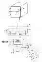
FIG. 1 depicts a system and method for displaying a 3D video image in which navigation and object selection can be achieved in accordance with an exemplary embodiment.
FIG. 2 depicts a geometrical relationship used in computing the depth of an object in 3D space based on left and right views of a stereoscopic image.
FIG. 3 depicts the use of lateral coordinates from left and right views to determine pixel depth.
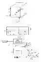
FIG. 4 depicts stereoscopic detection of a user navigation device for mapping its coordinates within 3D space in accordance with an exemplary embodiment.
FIG. 5 is a flow chart for using pixel coordinate information from left and right views to determine pixel depth.
DETAILED DESCRIPTION OF PREFERRED EMBODIMENTS
Referring to FIG. 1, a 3D video image includes multiple 3D video frames 10 having width X, height Y and depth Z, within which multiple picture elements, or pixels 12, exist to provide image information. Each pixel 12 will have its own lateral coordinate Xo, height coordinate Yo and depth coordinate Zo. These video frames tend typically to form a video signal 11, which is stored in a suitable storage medium 20, e.g., memory such as magnetic tape, a magnetic disc, flash memory, random access memory (RAM), a DVD, CD-ROM, or other suitable analog or digital storage media.
Such video frames 10 are typically encoded as two-dimensional (2D) video frames 22, 24 corresponding to left 22 and right stereoscopic 24 views. As a result, the original image element, e.g., 3D pixel 12, is encoded as a left pixel 121 and a right pixel 12r having lateral and height coordinate pairs (Xl, Yl) and (Xr, Yr), respectively. The original depth coordinate Zo, as discussed in more detail below, is a function of the distance between the lateral coordinates Xl, Xr of the left 22 and right 24 views.
During playback or display of the video frames, the encoded left 22 and right 24 video frames are accessed, e.g., by being read out from the storage medium 20 as a video signal 21 for processing by a suitable video or graphics processor 30, many types of which are well known in the art. This processor 30 (for which the executable processing instructions can be stored in the storage medium 20 or within other memory located within the host system or elsewhere, e.g., accessible via a network connection), in accordance with navigation/control information 55 (discussed in more detail below) provides a decoded video signal 31 to a display device 40 for display to a user. To achieve the 3D effect, the user typically wears a form of synchronized glasses 50 having left 511 and right 51r lenses synchronized to the alternating left and right views being displayed on the display device 40. Such synchronization, often achieved wirelessly, is done using a synchronization circuit 38 (e.g., by providing a wireless synchronization signal 39 to the glasses 50 in the form of radio frequency or infrared energy) in accordance with a control signal 37, 41 from the processor 30 or display 40.
Referring to FIG. 2, in accordance with well known geometrical principals, the distance or depth Zd of an object in 3D space can be determined based on image information from left L and right R stereoscopic views. The apex of the triangle as illustrated represents the maximum depth Zoo of the video frame, e.g., where the difference Xl−Xr between the lateral image coordinates Xl, Xr equals zero is at infinity, and the base of the triangle represents the minimum depth Z0 of the video frame, e.g., where the difference Xl−Xr between the lateral image coordinates Xl, Xr equals the maximum width of the viewable space. Accordingly, within the defined 3D image space, each pixel of an object being viewed will have a left lateral and height coordinate pair (Xl, Yl) and a right lateral and height coordinate pair (Xr, Yr), with each having associated therewith a depth coordinate Zd. As a result, the left view for a given image pixel will have a left lateral, height and depth coordinate set (Xl, Yl, Zd), and a corresponding right lateral, height and depth coordinate set (Xr, Yr, Zd).
Referring to FIG. 3, corresponding left 121 and right 12r pixels have pixel coordinates (XFL, YFL) and (XFR, YFR), respectively. Depth information is a function of the distance ΔX (the difference XFL-XFR between the lateral image coordinates XFL, XFR) between the left 121 and right 12r frame pixels. In accordance with well-known geometrical principals, the central lateral coordinate X for the base of the triangle for finding the depth Zd can be computed: X=XFL+ΔX/2=XFR−ΔX/2. The vertical coordinates are equal: Y=YFL=YFR. The depth Zd can then be computed: Zd=2*ΔX*tan∠L=2*ΔX*tan∠R.
Referring to FIG. 4, in accordance with an exemplary embodiment, the navigation/selection information 55 for processing by the processor 30 (FIG. 1) in conjunction with the video information 21 can be provided based on stereoscopic image information 551, 55r captured by left 541 and right 54r video image capturing devices (e.g., cameras) directed to view the three-dimensional space 100 within which a pointing device 52 is manipulated by a user (not shown). Such pointing device 52, as it is manipulated and moved about within such space 100, will have lateral Xu, height Yu and depth Zu coordinates. As discussed above, the image capturing devices 541, 54r will capture stereoscopic left and right images of the pointing device 52 with each such image having associated left and right lateral and height coordinate pairs (Xul, Yul), (Xur, Yur). As also discussed above, based on these coordinate pairs (Xul, Yul), (Xur, Yur), the corresponding depth coordinate Zu can be computed.
In accordance with well known principles, the minimum and maximum possible coordinate values captured by these image capturing devices 541, 54r are scaled and normalized to correspond to the minimum and maximum lateral (MIN(X) and MAX(X)), height (MIN(Y) and MAX(Y)) and depth (MIN(Z)=Z0 and MAX(Z)=Z∞) coordinates available within the 3D image space 10 (FIG. 1). As a result, a stereoscopic image of the pointing device can be placed within the 3D video frame 10 (FIG. 1) at the appropriate location within the frame. Accordingly, as the user-controlled pointing device 52 is moved about within its 3D space 100, the user will be able to navigate within the 3D space 10 of the video image as shown on the display device 40.
Referring to FIG. 5, a method 200 in accordance with an exemplary embodiment begins at process 201 by accessing image pixel data corresponding to a three-dimensional (3D) image element and including two-dimensional (2D) left image pixel data having left horizontal and vertical coordinates associated therewith and 2D right image pixel data having right horizontal and vertical coordinates associated therewith. This is followed by process 202 computing, based upon said left and right coordinates, a depth coordinate for said image element.
Additionally, integrated circuit design systems (e.g., work stations with digital processors) are known that create integrated circuits based on executable instructions stored on a computer readable medium including memory such as but not limited to CDROM, RAM, other forms of ROM, hard drives, distributed memory, or any other suitable computer readable medium. The instructions may be represented by any suitable language such as but not limited to hardware descriptor language (HDL) or other suitable language. The computer readable medium contains the executable instructions that when executed by the integrated circuit design system causes the integrated circuit design system to produce an integrated circuit that includes the devices or circuitry as set forth herein. The code is executed by one or more processing devices in a work station or system (not shown). As such, the devices or circuits described herein may also be produced as integrated circuits by such integrated circuit design systems executing such instructions.
Claims
What is claimed is:1. A method comprising:
accessing image pixel data corresponding to a three-dimensional (3D) image element and including two-dimensional (2D) left image pixel data having left horizontal and vertical coordinates associated therewith and 2D right image pixel data having right horizontal and vertical coordinates associated therewith; and
computing, based upon said left and right coordinates, a depth coordinate for said image element.
2. The method of claim 1, wherein said computing, based upon said left and right coordinates, a depth coordinate for said image element comprises computing said depth coordinate for said image element based upon said left and right horizontal coordinates.
3. The method of claim 1, wherein said computing, based upon said left and right coordinates, a depth coordinate for said image element comprises computing said depth coordinate for said image element in accordance with a difference between said left and right coordinates.
4. The method of claim 1, wherein said computing, based upon said left and right coordinates, a depth coordinate for said image element comprises computing said depth coordinate for said image element in accordance with a difference between said left and right horizontal coordinates.
5. An apparatus including circuitry, comprising:
programmable circuitry for
accessing image pixel data corresponding to a three-dimensional (3D) image element and including two-dimensional (2D) left image pixel data having left horizontal and vertical coordinates associated therewith and 2D right image pixel data having right horizontal and vertical coordinates associated therewith, and
computing, based upon said left and right coordinates, a depth coordinate for said image element.
6. The apparatus of claim 5, wherein said programmable circuitry is for computing said depth coordinate for said image element based upon said left and right horizontal coordinates.
7. The apparatus of claim 5, wherein said programmable circuitry is for computing said depth coordinate for said image element in accordance with a difference between said left and right coordinates.
8. The apparatus of claim 5, wherein said programmable circuitry is for computing said depth coordinate for said image element in accordance with a difference between said left and right horizontal coordinates.
9. An apparatus, comprising:
memory capable of storing executable instructions; and
at least a first processor operably coupled to said memory and responsive to said executable instructions by
accessing image pixel data corresponding to a three-dimensional (3D) image element and including two-dimensional (2D) left image pixel data having left horizontal and vertical coordinates associated therewith and 2D right image pixel data having right horizontal and vertical coordinates associated therewith, and
computing, based upon said left and right coordinates, a depth coordinate for said image element.
10. The apparatus of claim 9, wherein said at least a first processor is responsive to said executable instructions by computing said depth coordinate for said image element based upon said left and right horizontal coordinates.
11. The apparatus of claim 9, wherein said at least a first processor is responsive to said executable instructions by computing said depth coordinate for said image element in accordance with a difference between said left and right coordinates.
12. The apparatus of claim 9, wherein said at least a first processor is responsive to said executable instructions by computing said depth coordinate for said image element in accordance with a difference between said left and right horizontal coordinates.
13. A computer readable medium comprising a plurality of executable instructions that, when executed by an integrated circuit design system, cause the integrated circuit design system to produce:
an integrated circuit (IC) including programmable circuitry for
accessing image pixel data corresponding to a three-dimensional (3D) image element and including two-dimensional (2D) left image pixel data having left horizontal and vertical coordinates associated therewith and 2D right image pixel data having right horizontal and vertical coordinates associated therewith, and
computing, based upon said left and right coordinates, a depth coordinate for said image element.
14. The apparatus of claim 13, wherein said programmable circuitry is for computing said depth coordinate for said image element based upon said left and right horizontal coordinates.
15. The apparatus of claim 13, wherein said programmable circuitry is for computing said depth coordinate for said image element in accordance with a difference between said left and right coordinates.
16. The apparatus of claim 13, wherein said programmable circuitry is for computing said depth coordinate for said image element in accordance with a difference between said left and right horizontal coordinates.
Images & Drawings included:


Sources:
- United States Patent and Trademark Office - verify current appl. status at the USPTO↗
Recent applications in this class:
- » 20130258466 2013-10-03
STEREOSCOPIC IMAGE DISPLAY DEVICE AND DRIVING METHOD THEREOF - » 20130188252 2013-07-25
Eyewear device for transmitting signal and communication method thereof - » 20130187899 2013-07-25
Glasses apparatus and power supply apparatus - » 20130106835 2013-05-02
Stereoscopic Display System and Driving Method Thereof - » 20130088655 2013-04-11
Stereoscopic display system with active switchable retarder - » 20130083392 2013-04-04
MECHANISM FOR EMPLOYING AND FACILITATING A UNIVERSAL AND DYNAMIC EYEWEAR OPTICAL LENS STACK AND AN INTELLIGENT TRACKING SYSTEM AT AN EYEWEAR DEVICE - » 20130076998 2013-03-28
Optical device - » 20130070173 2013-03-21
LIQUID-CRYSTAL DISPLAY DEVICE - » 20130068950 2013-03-21
3D EYEGLASS - » 20130063814 2013-03-14
THREE DIMENSIONAL GLASSES
Recent applications for this Assignee:
- » 20250176154 2025-05-29
DEVICES AND SYSTEMS FOR FLYING BITLINE WITH JUMPER CELL - » 20250157946 2025-05-15
APPARATUS, SYSTEM, AND METHOD FOR MITIGATING WARPAGE IN INTEGRATED CIRCUIT PACKAGES - » 20250157142 2025-05-15
DEVICES, SYSTEMS, AND METHODS FOR GENERATING THREE-DIMENSIONAL AVATARS OF USERS - » 20250117523 2025-04-10
SYSTEMS AND METHODS FOR SOFT FUSE OVERRIDE - » 20250117472 2025-04-10
METHODS AND SYSTEMS FOR SYNCHRONIZING TRUSTED OPERATING SYSTEMS - » 20250111638 2025-04-03
IMAGING PRIVACY FILTER FOR OBJECTS OF INTEREST IN HARDWARE FIRMWARE PLATFORM - » 20250111601 2025-04-03
SPATIOTEMPORAL ADAPTIVE SHADING RATES FOR DECOUPLED SHADING - » 20250111599 2025-04-03
TEMPORAL SHADING RATE CONTROLLER FOR DECOUPLED SHADING - » 20250111598 2025-04-03
HYBRID DEFERRED DECOUPLED RENDERING - » 20250111587 2025-04-03
SIMPLIFIED LOW-PRECISION RAY INTERSECTION THROUGH ACCELERATED HIERARCHY STRUCTURE PRECOMPUTATION