Electrical connector and method of making the same
US20130052877A1
2013-02-28
13/589,093
2012-08-18
✅ Patent granted
US 8,696,381 B2
2014-04-15
-
-
Ross Gushi
Wei Te Chung | Ming Chieh Chang
2032-09-27
Abstract:
An electrical connector (100) for electrically connecting an IC package with a substrate includes a number of conductive contacts (4), a number of grounding terminals (5), an insulative member (32) made of insulation materials locates around the conductive contacts (4) with insert-molded method and an electrical member (1) made of electrical resin locates around the insulative member (32) and the grounding terminals (5) with insert-molded method, the conductive contacts (4) are insulated from the electrical member (1) and the grounding terminals (5) are electrically connected with the electrical member (1).
Assignee:
- HON HAI PRECISION INDUSTRY CO., LTD. 10,014 🇹🇼 New Taipei, Taiwan
Applicant:
Interested in similar patents?
Get notified when new applications in this technology area are published.
Classification:
H01R13/504 » CPC main
Details of coupling devices of the kinds covered by groups or -; Bases; Cases composed of different pieces different pieces being moulded, cemented, welded, e.g. ultrasonic, or swaged together
H01R13/6599 » CPC further
Details of coupling devices of the kinds covered by groups or -; Protective earth or shield arrangements on coupling devices, e.g. anti-static shielding ; High frequency shielding arrangements, e.g. against EMI [Electro-Magnetic Interference] or EMP [Electro-Magnetic Pulse]; Shield material Dielectric material made conductive, e.g. plastic material coated with metal
H01R12/73 » CPC further
Structural associations of a plurality of mutually-insulated electrical connecting elements, specially adapted for printed circuits, e.g. printed circuit boards [PCBs], flat or ribbon cables, or like generally planar structures, e.g. terminal strips, terminal blocks; Coupling devices specially adapted for printed circuits, flat or ribbon cables, or like generally planar structures; Terminals specially adapted for contact with, or insertion into, printed circuits, flat or ribbon cables, or like generally planar structures; Coupling devices for rigid printing circuits or like structures coupling with the edge of the rigid printed circuits or like structures connecting to other rigid printed circuits or like structures
Y10T29/4922 » CPC further
Metal working; Method of mechanical manufacture; Electrical device making; Conductor or circuit manufacturing; Contact or terminal manufacturing by assembling plural parts with molding of insulation
H01R24/28 IPC
Two-part coupling devices, or either of their cooperating parts, characterised by their overall structure Coupling parts carrying pins, blades or analogous contacts and secured only to wire or cable
H01R43/24 » CPC further
Apparatus or processes specially adapted for manufacturing, assembling, maintaining, or repairing of line connectors or current collectors or for joining electric conductors for assembling or disassembling contact members with insulating base, case or sleeve Assembling by moulding on contact members
H01R13/648 IPC
Details of coupling devices of the kinds covered by groups or - Protective earth or shield arrangements on coupling devices, e.g. anti-static shielding
Description
BACKGROUND OF THE INVENTION
1. Field of the Invention
The present invention relates to an electrical connector and method of making the same, and more particularly to an electrical connector using insert-molded method to position conductive contacts and grounding terminals.
2. Description of Related Art
Chinese patent No. 201498709 issued to Chang on Jun. 2, 2010 discloses a conventional electrical connector for electrically connecting an IC package with a substrate. The electrical connector includes a base with a number of conductive contacts and a number of grounding terminals received therein. The base is made of copper or similar conductive materials. There is an insulation member locating around the conductive contact to insulate the conductive contact and the base. The grounding terminals contact with the base to establish an electrical path. Due to the base is made of copper and also need to manufacture a number of holes to receive the conductive contacts and the grounding terminals, thus made the electrical connector high-cost.
Hence, it is desirable to provide an improved electrical connector to overcome the aforementioned disadvantages.
SUMMARY OF THE INVENTION
Accordingly, an object of the present invention is to provide an electrical connector using insert-molded method to position conductive contacts and grounding terminals.
According to one aspect of the present invention, an electrical connector for electrically connecting an IC package with a substrate comprises a number of conductive contacts, a number of grounding terminals, an insulative member locates around the conductive contacts with insert-molded method and an electrical member locates around the insulative member and the grounding terminals with insert-molded method. The insulative member is made of insulation materials. The electrical member is made of electrical resin. The conductive contacts are insulated from the electrical member and the grounding terminals are electrically connected with the electrical member.
Other objects, advantages and novel features of the invention will become more apparent from the following detailed description when taken in conjunction with the accompanying drawings, in which:
BRIEF DESCRIPTION OF THE DRAWINGS
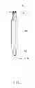
FIG. 1 is an isometric view of a conductive contact according to a preferred embodiment of the present invention;
FIG. 2 is an isometric view of part members of an electrical connector according to a preferred embodiment of the present invention, showing insulative member and lower insulative member locating on the conductive contacts and grounding terminals;
FIG. 3 is an isometric view of part members of an electrical connector according to a preferred embodiment of the present invention, showing an electrical member locating on the insulative member;
FIG. 4 is an isometric view of an electrical connector according to a preferred embodiment of the present invention; and
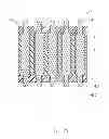
FIG. 5 is a cross-sectional view of the electrical connector taken along line 5-5 in FIG. 4.
DETAILED DESCRIPTION OF THE INVENTION
Reference will now be made to the drawings to describe the present invention in detail.
FIGS. 4 to 5 illustrate an electrical connector 100 in accordance to a preferred embodiment of the present invention, the electrical connector 100 is used for electrically connecting an IC package (not labeled) with a substrate (not labeled). The electrical connector 100 comprises a number of conductive contacts 4, a number of grounding terminals 5, an insulative member 32 located around the conductive contacts 4, an electrical member 1 made of electrical resin located around the insulative member 32 and the grounding terminals 5. The electrical connector 100 also comprises an upper insulative member 2 locates on upper end of the electrical member 1 and a lower insulative member 31 locates on lower end of the electrical member 1. The electrical resin is made of liquid crystal polyester.
Referring to FIGS. 1-2 and FIG. 5, the conductive contact 4 is configured to a cylinder type and comprises a body portion 40, an upper end 41 extending upwardly from the body portion 40 and a lower end 42 extending downwardly from the body portion 40. The cross-sectional area of the body portion 40 is larger than that of the upper end 41 and that of the lower end 42. The free end of the upper end 41 defines an upper contact portion 410 and the free end of the lower end defines a lower contact portion 420.
The upper contact portion 410 extends beyond the upper insulative member 2 to electrically connecting with the IC package. The lower contact portion 420 extends beyond the lower insulative member 31 to electrically connecting with the substrate. The height of the insulative member 32 equals to that of the body portion 40 of the conductive contact 4 and that of the electrical member 1. The conductive contacts 4 are insulated from the electrical member 1. The grounding terminals 5 have a same structure with the conductive contacts 4 and are electrically connected with the electrical member 1.
Referring to FIGS. 1-4, the electrical connector 100 is made by insert-molded method. The steps are as following: firstly, providing a number of conductive contacts 4 and a number of grounding terminals 5; secondly, providing an insulative member 32 and a lower insulative member 31 made of insulation materials insert-molded with the conductive contacts 4 and the grounding terminals 5; thirdly, providing an electrical member 1 made of electrical resin located around the insulative member 32 and the grounding terminals 5 with insert-molded method, the conductive contacts 4 are insulated from the electrical member 1 and the grounding terminals 5 are electrically connected with the electrical member 1; then, providing an upper insulative member 2 made of insulation materials insert-molded with the conductive contacts 4 and the grounding terminals 5. The electrical connector 100 is easy to make and can save the cost.
While the preferred embodiments in accordance with the present invention has been shown and described, equivalent modifications and changes known to persons skilled in the art according to the spirit of the present invention are considered within the scope of the present invention as defined in the appended claims.
Claims
What is claimed is:1. An electrical connector for electrically connecting an IC package with a substrate, comprising:
a number of conductive contacts;
a number of grounding terminals;
an insulative member made of insulation materials located around the conductive contacts with insert-molded method; and
an electrical member made of electrical resin located around the insulative member and the grounding terminals with insert-molded method, the conductive contacts being insulated from the electrical member and the grounding terminals being electrically connected with the electrical member.
2. The electrical connector as claimed in claim 1, wherein the electrical resin is made of liquid crystal polyester.
3. The electrical connector as claimed in claim 1, wherein further includes a lower insulative member locates on lower end of the electrical member.
4. The electrical connector as claimed in claim 3, wherein the lower insulative member and the insulative member are made in a same time to position the conductive contacts and the grounding terminals.
5. The electrical connector as claimed in claim 3, wherein further includes an upper insulative member locates on upper end of the electrical member.
6. The electrical connector as claimed in claim 5, wherein the conductive contact includes a body portion located in the insulative member, an upper contact portion extending beyond the upper insulative member and a lower contact portion extending beyond the lower insulative member.
7. The electrical connector as claimed in claim 6, wherein the grounding terminals have a same structure with the conductive contacts.
8. The electrical connector as claimed in claim 6, wherein the height of the insulative member equals to that of the body portion of the conductive contact and that of the electrical member.
9. A method for making an electrical connector, comprising the steps of:
S1) providing a number of conductive contacts and a number of grounding terminals;
S2) providing an insulative member made of insulation materials located around the conductive contacts with insert-molded method; and
S3) providing an electrical member made of electrical resin located around the insulative member and the grounding terminals with insert-molded method, the conductive contacts being insulated from the electrical member and the grounding terminals being electrically connected with the electrical member.
10. The method as claimed in claim 9, wherein the electrical resin is made of liquid crystal polyester.
11. The method as claimed in claim 9, wherein further includes a step to provide a lower insulative member locates on lower end of the electrical member.
12. The method as claimed in claim 11, wherein the lower insulative member and the insulative member are made in a same step to position the conductive contacts and the grounding terminals.
13. The method as claimed in claim 11, wherein further includes a step to provide an upper insulative housing locates on upper end of the electrical member with insert-molded method.
14. The method as claimed in claim 12, wherein the conductive contact includes a body portion located in the insulative member, an upper contact portion extending beyond the upper insulative member and a lower contact portion extending beyond the lower insulative member.
15. The method as claimed in claim 14, wherein the grounding terminals have a same structure with the conductive contacts.
16. The method as claimed in claim 14, wherein the height of the insulative member equals to that of the body portion of the conductive contact and that of the electrical member.
17. An electrical connector comprising:
a plurality of conductive contacts each circumferentially surrounded by an insulative sleeve via a first insert molding with two opposite ends exposed to an exterior in a vertical direction; and
said contacts associated with the corresponding sleeves further integrally embedded within a conductive housing made of conductive resin, via a second insert molding; wherein
the contacts are isolated from the conductive housing by the corresponding sleeves which intimately mechanically and electrically contact the conductive housing under proper securement therebetween.
18. The electrical connector as claimed in claim 17, wherein the securement between the sleeve and the conductive housing performs elasticity thereof.
19. The electrical connector as claimed in claim 17, further including other contacts without corresponding sleeves associated therewith and directly mechanically and electrically circumferentially connected to the conductive housing for grounding.
20. The electrical connector as claimed in 17, wherein two opposite ends of each of said contacts are narrowed and covered by corresponding insulative parts, respectively, for anti-shorting consideration.
Images & Drawings included:


Sources:
- United States Patent and Trademark Office - verify current appl. status at the USPTO↗
Similar patent applications:
- » 20090029575
Electrical connector and method of making contacts thereof with electrical connector and method of making the same - » 20210281001
Electrical connector and method of making an electrical connector - » 20230369792
ELECTRICAL CONNECTOR WITH IMPROVED RELIABILITY, CONNECTOR ASSEMBLY, AND METHOD OF MAKING ELECTRICAL CONNECTOR - » 20240063573
Electrical connector and method of making an electrical connection - » 20190052021
Electrical connector and method making the same - » 20200052429
Electrical connector and method making the same - » 20100075514
Method of making electrical connector on a flexible carrier - » 20060258183
Method of making electrical connector on a flexible carrier - » 10208538
Apparatus and method for making electrical connectors - » 20070261236
Method of making electrical connector
Recent applications for this Assignee:
- » 20250218287 2025-07-03
METHOD OF GENERATING AND PROMPTING TRAFFIC INFORMATION, AND ROADSIDE DEVICE THEREOF - » 20250178535 2025-06-05
METHOD FOR CONSTRUCTING 3D PANORAMIC VIEW MODEL, VEHICLE-MOUNTED DEVICE, AND STORAGE MEDIUM - » 20250074444 2025-03-06
METHOD FOR EARLY WARNING A BLIND AREA, ELECTRONIC DEVICE AND STORAGE MEDIUM - » 20240416754 2024-12-19
DISPLAY CONTROL DEVICE, DISPLAY EQUIPMENT, AND VEHICLE EMPLOYING DEVICE - » 20240411051 2024-12-12
Light-emitting device array and optical transceiver system having the same - » 20240324114 2024-09-26
DISPLAY CONTROL DEVICE AND VEHICLE EMPLOYING DEVICE - » 20240295957 2024-09-05
METHOD FOR CONTROLLING ELECTRONIC DEVICE, ELECTRONIC DEVICE AND COMPUTER STROAGE MEDIUM EMPLOYING METHOD - » 20240257357 2024-08-01
METHOD FOR DETECTING OBSTACLES, ELECTRONIC DEVICE, AND STORAGE MEDIUM - » 20240203133 2024-06-20
LANE LINE RECOGNITION METHOD, ELECTRONIC DEVICE AND STORAGE MEDIUM - » 20240194999 2024-06-13
Robot using limiting device for locking battery