HEAT DISSIPATION MODULE AND METHOD OF USING THE HEAT DISSIPATION MODULE
US20130248161A1
2013-09-26
13/537,263
2012-06-29
Abstract:
A heat dissipation module includes a heat sink. A plurality of grooves are defined in a bottom surface of the heat sink, a heat pipe is accommodated in each groove of the heat sink, and a heat conducting pad made of phase change material is adhered to the bottom surface of the heat sink to cover the grooves and the heat pipes. The heat conducting pad is a solid material at an ambient room temperature. When heated to a temperature higher than a transition temperature of the heat conducting pad, the heat conducting pad softens to fill spaces between the heat conducting pad, the heat sink, and the heat pipes.
Inventors:
- WEN-CHIEH WANG 6 🇹🇼 Tu-Cheng, Taiwan
- PEI-CHUN KO 1 🇹🇼 Tu-Cheng, Taiwan
- CHUN-SHENG YU 1 🇹🇼 Tu-Cheng, Taiwan
- WEI-DE WANG 1 🇹🇼 Tu-Cheng, Taiwan
- CHIH-SHENG HSIEH 4 🇹🇼 Tu-Cheng, Taiwan
- CHUNG-JEN HUNG 1 🇹🇼 Tu-Cheng, Taiwan
- GIN-ZEN TING 1 🇹🇼 Tu-Cheng, Taiwan
Assignee:
- HON HAI PRECISION INDUSTRY CO., LTD. 12,828 🇹🇼 Tu-Cheng, Taiwan
Interested in similar patents?
Get notified when new applications in this technology area are published.
Classification:
F28D15/0275 » CPC main
Heat-exchange apparatus with the intermediate heat-transfer medium in closed tubes passing into or through the conduit walls ; Heat-exchange apparatus employing intermediate heat-transfer medium or bodies in which the medium condenses and evaporates, e.g. heat pipes Arrangements for coupling heat-pipes together or with other structures, e.g. with base blocks; Heat pipe cores
F28D20/02 » CPC further
Heat storage plants or apparatus in general; Regenerative heat-exchange apparatus not covered by groups or using latent heat
H01L23/427 » CPC further
Details of semiconductor or other solid state devices; Arrangements for cooling, heating, ventilating or temperature compensation ; Temperature sensing arrangements; Fillings or auxiliary members in containers or encapsulations selected or arranged to facilitate heating or cooling Cooling by change of state, e.g. use of heat pipes
H01L23/467 » CPC further
Details of semiconductor or other solid state devices; Arrangements for cooling, heating, ventilating or temperature compensation ; Temperature sensing arrangements involving the transfer of heat by flowing fluids by flowing gases, e.g. air
Y02E60/14 » CPC further
Enabling technologies; Technologies with a potential or indirect contribution to GHG emissions mitigation Thermal energy storage
Y02E60/14 » CPC further
Enabling technologies; Technologies with a potential or indirect contribution to GHG emissions mitigation Thermal energy storage
H01L2924/0002 » CPC further
Indexing scheme for arrangements or methods for connecting or disconnecting semiconductor or solid-state bodies as covered by; Technical content checked by a classifier Not covered by any one of groups , and
H01L2924/00 » CPC further
Indexing scheme for arrangements or methods for connecting or disconnecting semiconductor or solid-state bodies as covered by
F28F1/20 IPC
Tubular elements; Assemblies of tubular elements; Tubular elements and assemblies thereof with means for increasing heat-transfer area, e.g. with fins, with projections, with recesses the means being only outside the tubular element and extending longitudinally the means being attachable to the element
Description
BACKGROUND
1. Technical Field
The present disclosure relates to a heat dissipation module for an electronic component and a method using the heat dissipation module.
2. Description of Related Art
To get a good balance between heat dissipation effectiveness and cost, a heat dissipation module for an electronic component, such as a central processing unit, may comprise an aluminum heat sink, and a plurality of copper heat pipes fitted in grooves defined in a bottom side of the heat sink. However, because of the size of the heat pipes and assembly tolerances, when the heat dissipation module is seated on an electronic component, there may be spaces between the electronic components and the bottom side of the heat sink and the heat pipes. The spaces do not allow contact between the pipe and the heat sink and reduces the efficiency of head dissipation from the electronic component.
BRIEF DESCRIPTION OF THE DRAWINGS
Many aspects of the present embodiments can be better understood with reference to the following drawings. The components in the drawings are not necessarily drawn to scale, the emphasis instead being placed upon clearly illustrating the principles of the present embodiments. Moreover, in the drawings, like reference numerals designate corresponding parts throughout the views.
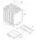
FIG. 1 is an exploded, isometric view of an exemplary embodiment of a heat dissipation module.
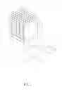
FIG. 2 shows the heat dissipation module in use.
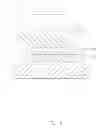
FIGS. 3 and 4 are sectional views taken along the line III-III of FIG. 2, but respectively showing before and after the heat dissipation module being heating.
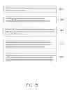
FIG. 5 is a flowchart of an exemplary embodiment of a method using the heat dissipation module of FIG. 2.
DETAILED DESCRIPTION
The disclosure, including the accompanying drawings, is illustrated by way of examples and not by way of limitation. It should be noted that references to “an” or “one” embodiment in this disclosure are not necessarily to the same embodiment, and such references can mean “at least one.”
FIG. 1, is an exemplary embodiment of a heat dissipation module. The heat dissipation module includes a heat sink 10, a plurality of heat pipes 20, and a heat conductive pad 30 made of phase change material.
The heat sink 10 includes a base plate 11 and a plurality of fins 12 perpendicularly extending from a top surface of the base plate 11. A plurality of grooves 112 is defined in a bottom surface of the base plate 11 opposite to the fins 12.
Each heat pipe 20 has a rounded cross section.
The heat conductive pad 30 is a flexible solid material at ambient room temperature. A top surface of the heat conductive pad 30 is adhesive and covered with a protective film (not shown) before use. The heat conductive pad 30 softens when heated to a phase-transition temperature of the heat conductive pad 30.
Referring to FIGS. 2 and 3, in assembly, the heat pipes 20 are forced to be deformed to be tightly engaged in the corresponding grooves 112 of the heat sink 10. The protective film of the heat conductive pad 30 is removed, and then the heat conductive pad 30 is adhered to the bottom surface of the base plate 11 of the heat sink 10 to cover the grooves 112 and the heat pipes 20. Due to geometric differences, there will be spaces 1020 between the heat conductive pad 30, the bottom surface of the heat sink 10, and the heat pipes 20.
FIGS. 3-5, shows a method to use the heat dissipation module of FIG. 2. The method for dissipating heat for an electronic component 200 includes the following steps.
In step S01, a heat sink 10 with a plurality of grooves 12 defined in a bottom surface of the heat sink 20 is provided.
In step S02, providing a plurality of heat pipes 20. The plurality of heat pipes 20 correspondingly engage in the grooves 12 of the heat sink 10.
In step S03, providing a heat conductive pad 30 made of phase change material.
The heat conductive pad 30 is adhered to the bottom surface of the heat sink 10 covering the grooves 12 and the heat pipes 20;
In step S04, the heat sink is seated on the electronic component 200, with a bottom surface of the heat conductive pad 30 opposite to the heat sink 10 abutting against a top surface of the electronic component 200.
In step S05, the heat conductive pad 30 is softened by heating the heat conductive pad 30 to a temperature greater than the phase-transition temperature of the heat conductive pad 30. Since the electronic component 200 generates heat in operation, in one embodiment, the heat conductive pad 30 is heated by heat generated by the electronic component 200.
It is to be understood, however, that even though numerous characteristics and advantages of the embodiments have been set forth in the foregoing description, together with details of the structures and functions of the embodiments, the disclosure is illustrative only, and changes may be made in detail, especially in the matters of arrangement of parts within the principles of the present disclosure to the full extent indicated by the broad general meaning of the terms in which the appended claims are expressed.
Claims
What is claimed is:1. A heat dissipation module, comprising:
a heat sink defining a plurality of grooves in a bottom surface of the heat sink;
a plurality of heat pipes accommodated in the grooves of the heat sink; and
a heat conductive pad adhered to the bottom surface of the heat sink to cover the grooves and the heat pipes, wherein the heat conductive pad is a tacky, flexible solid at an ambient room temperature, and softens when heated to a temperature higher than a transition temperature of the heat conductive pad fill spaces between the heat conductive pad, the heat sink, and the heat pipes.
2. The heat dissipation module of claim 1, wherein the heat sink comprises a base plate and a plurality of fins perpendicularly extending from a top surface of the base plate, the embedded grooves are defined in a bottom surface of the base plate.
3. A method of dissipating heat, comprising:
providing a heat sink defining a plurality of grooves in a bottom surface of a heat sink;
providing a plurality of heat pipes correspondingly accommodated in the grooves of the heat sink;
providing a heat conductive pad made of phase change material adhered to the bottom surface of the heat sink to cover the grooves and the heat pipes;
mounting the heat sink on an electronic component, with a bottom surface of the heat conductive pad opposite to the heat sink and abutting against a top surface of the electronic component; and
softening the heat conductive pad by heating to fill spaces between the heat sink, the heat pipes, and the heat conductive pad.
4. The method of claim 1, wherein the softening step comprises heating the heat conductive pad to a temperature higher than a transition temperature of the heat conductive pad.
5. The method of claim 4, wherein the heat conductive pad is heated by heat generated by the electronic component.
Images & Drawings included:


Sources:
- United States Patent and Trademark Office - verify current appl. status at the USPTO↗
Similar patent applications:
- » 20190017667
LED (LIGHT EMITTING DIODE) LUMINAIRES, HEAT DISSIPATION MODULES AND METHODS OF USE - » 20100091464
Heat dissipating structure base board, module using heat dissipating structure base board, and method for manufacturing heat dissipating structure base board - » 20130286585
HEAT DISSIPATING MODULE, AND ELECTRONIC DEVICE AND OPERATING METHOD USING SAME - » 20140241673
Heat dissipation device and method for use in an optical communications module
Recent applications in this class:
- » 20130299155 2013-11-14
Heat dissipation device assembly structure - » 20130255927 2013-10-03
Heat dissipating device - » 20130153200 2013-06-20
System for cooling buildings containing heat generating electronics - » 20130126125 2013-05-23
Thin heat pipe having recesses for fastener - » 20130120926 2013-05-16
User-serviceable liquid DIMM cooling system - » 20130118718 2013-05-16
HEAT PIPE ASSEMBLY - » 20130105132 2013-05-02
HEAT SINK FIN AND HEAT SINK DEVICE - » 20130075064 2013-03-28
Heat Exchanger - » 20130056179 2013-03-07
Thermal module structure - » 20130025830 2013-01-31
HEAT SINK ASSEMBLY OF FIN MODULE AND HEAT PIPES
Recent applications for this Assignee:
- » 20140233961 2014-08-21
Optical communication module including optical-electrical signal converters and optical signal generators - » 20140083669 2014-03-27
HEAT SINK - » 20140063746 2014-03-06
Electronic device with heat dissipation assembly - » 20140061224 2014-03-06
AUTOMATIC VENDING MACHINE - » 20140060914 2014-03-06
Enclosure with shield apparatus - » 20140058727 2014-02-27
MULTIMEDIA RECORDING SYSTEM AND METHOD - » 20140055955 2014-02-27
Fastener - » 20140055322 2014-02-27
DISPLAY SYSTEM AND HEAD-MOUNTED DISPLAY APPARATUS - » 20140054439 2014-02-27
CONTAINER DATA CENTER WITH SUPPORTING APPARATUS - » 20140054311 2014-02-27
AUTOMATIC VENDING MACHINE WITH MOVING MEMBER FOR PRODUCTS