Optical inspection system with a variation system consisting of five lens groups for imaging an object into infinity
US20130308201A1
2013-11-21
13/989,398
2011-11-07
✅ Patent granted
US 9,151,936 B2
2015-10-06
WO; PCT/EP2011/069508; 20111107
WO; WO2012/069304; 20120531
James Jones
Patterson Thuente Pedersen, P.A.
2032-04-17
Abstract:
The invention relates to an optical inspecting system designed to image an object to be inspected with a variable imaging scale, comprising a variation system for imaging the object into infinity, a lens group downstream of the variation system for imaging the object from infinity into the image plane of the whole system, and a light source for generating light in order to illuminate the object, means for imaging the illuminating light into the exit pupil of the variation system being provided in the airspace between the fifth lens group and the subsequent lens group. Of the five lens groups of the variation system, the first, second, and fourth lens groups, when seen in the imaging direction, are arranged in a movable manner in the direction of the optical axis, whereas the third and fifth lens groups are not movable.
Inventors:
- Rolf Wartmann 14 🇩🇪 Waake, Germany
- Kerstin Winkler 1 🇩🇪 Goettingen, Germany
- Joerg Sprenger 1 🇩🇪 Jena, Germany
Assignee:
- CARL ZEISS MICROSCOPY GMBH 692 🇩🇪 Jena, Germany
Applicant:
Interested in similar patents?
Get notified when new applications in this technology area are published.
Classification:
G02B15/14 » CPC main
Optical objectives with means for varying the magnification by axial movement of one or more lenses or groups of lenses relative to the image plane for continuously varying the equivalent focal length of the objective
G02B21/02 IPC
Microscopes Objectives
G02B21/025 » CPC further
Microscopes; Objectives with variable magnification
G02B3/02 IPC
Simple or compound lenses with non-spherical faces
G02B13/22 » CPC further
Optical objectives specially designed for the purposes specified below Telecentric objectives or lens systems
G02B15/173 » CPC further
Optical objectives with means for varying the magnification by axial movement of one or more lenses or groups of lenses relative to the image plane for continuously varying the equivalent focal length of the objective with interdependent non-linearly related movements between one lens or lens group, and another lens or lens group having a first movable lens or lens group and a second movable lens or lens group, both in front of a fixed lens or lens group having an additional fixed front lens or group of lenses arranged +-+
G02B21/22 » CPC further
Microscopes; Arrangements with more than one light path, e.g. for comparing two specimens; Binocular arrangements Stereoscopic arrangements
Description
PRIORITY CLAIM
The present application is a National Phase entry of PCT Application No. PCT/EP2011/069508, filed Nov. 7, 2011, which claims priority from DE Application No. 10 2010 061 862.4, filed Nov. 24, 2010, said applications being hereby incorporated by reference herein in their entirety.
FIELD OF THE INVENTION
The invention relates to an optical inspection system, designed to image an object to be inspected with a variable imaging scale. It comprises a variation system consisting of several lens groups, a lens group downstream of the variation system for imaging the object into the image plane of the inspection system, and a light source for generating light in order to illuminate the object.
DESCRIPTION OF PRIOR ART
Optical inspection systems of this kind work fast and contact-free, and therefore are suitable especially for use in connection with digital image processing systems.
Their capabilities are limited, however, if object details of special interest are to be subjected to closer examination. If object details are additionally magnified with the systems known so far, only so-called empty magnifications are achieved, because the numerical aperture is not increased at the same time. Such magnification with unchanged aperture results in the disadvantage that the illuminance decreases considerably, both in the object and the image plane.
If, on top of that, the object is illuminated sideways, shadows in the object field will result. Object details within the shadow areas are difficult to resolve and therefore prone to misinterpretation.
DESCRIPTION OF THE INVENTION
Departing from this, the problem of the invention is to advance an optical inspection system of the kind mentioned in the beginning, in such a way that the advancement remedies the disadvantages of prior art. This should be achieved with the least possible technical outlay.
According to the invention, this problem is solved in such a way that
-
- the variation system consists of five lens groups and is designed to image the object into infinity,
- the lens group downstream of the variation system is intended for imaging the object from infinity into the image plane of the inspection system, and
- means for imaging the illuminating light into the exit pupil of the variation system are provided in the air space between the fifth lens group and the subsequent lens group.
Of the five lens groups of the variation system, the first, second and fourth lens groups (as seen in the imaging direction) are arranged so as to be movable along the optical axis, whereas the third and fifth lens group are not movable.
In other words: The problem is solved by means of a five-component variation system that is followed by a relatively large air space intended for feeding in the illumination, and another lens group. The first lens group of the variation system is movable along the optical axis; is in intended for setting the distance to the object. The second and fourth lens groups are movable as well; they effect a variation of the imaging scale by a factor of 16× . . . 20×. Thanks to a special coupling of the movements of these two lens groups according to the invention, a variation of the position of the image plane is prevented. The variation system images the object to be inspected into infinity. Therefore, the subsequent largish air space is ideal for feeding in the illumination. The collecting lens group following the air space images the object from infinity into the image plane of the overall system.
Remark: In this invention description, the term “lens group” is used as a synonym of the term “lens component” commonly used in prior art.
The means for imaging the illuminating light into the exit pupil of the variation system, optionally provided between the last lens group of the variation system and the subsequent collecting lens group, the formation of disturbing shadows on the object field to be observed is prevented to the greatest possible extent, since the object is now illuminated from the direction of observation.
Furthermore, due the invention, the object-side numerical aperture increases with increasing imaging scale, which advantageously results in an increase in resolution as well as in illuminance in the object plane. The accompanying decrease in brightness in the image plane is but insignificant as compared with prior art.
The first lens group consists of a cemented doublet, the focal length of which is positive and between 160 mm and 125 mm long. Its free diameter is at least 40 mm. It preferably consists of a collecting lens of fluor crown glass and a diverging lens of short flint glass. Arranged after this cemented doublet in imaging direction may be a zero-refraction meniscus, which is preferably convex on the object side.
The second lens group has a negative focal length between 25.5 mm and 30.5 mm. Its movement range along the optical axis is preferably twice as long as the amount of its focal length.
The third lens group has a positive focal length between 43 mm and 44.5 mm. It consists of two or three collecting lenses, with at least two of these lenses consisting of fluor crown glass. Preferably, this lens group is an achromatically corrected one.
The fourth lens group has a negative focal length between 37 mm and 44 mm. It is designed as a cemented doublet comprising a collecting lens of short flint glass. Its movement range along the optical axis is preferably up to 1.35 times the amount of its focal length.
The fifth lens group has a positive focal length between 179 mm and 184 mm. It is designed as a cemented doublet comprising a collecting lens of fluor crown glass and a diverging lens of short flint glass.
Between the third lens group and the fourth lens group an aperture diaphragm is provided.
The collecting lens group following the variation system is a fully corrected, especially achromatized optical system having a light conductance of 1.15.
An essential advantage of the invented optical inspection system is that the imaging scale is variable by a factor of at least 16×. At the same time, a variation of the numerical aperture is achieved, so that a greater imaging scale also leads to an increase in resolution. The distance between the object to be inspected and the first lens group is freely selectable by means of internal focusing and thus permits of a further increase in imaging scale.
The system is further designed to permit the observation of relatively large objects, which can be observed from a distance of 1 m to 5 m. At the smallest magnification, the object is observed or photographed with a viewing angle of about 25°. On the image side, a light conductance (the product of numerical aperture and image size) of 0.575 to 1.15 is achieved, so that—in combination with a diffraction-limited, apochromatic correction—the capabilities of modern, high-resolution digital cameras can be exhausted to advantage.
In designing the behavior of the numerical aperture versus the various zoom positions, the inventors have found a balance between technical outlay and constancy of illuminance in the image plane. The ideal state would be a constant image-side aperture of 0.05, because this would result in constant resolving power on the image side. Under this condition, and given constant illuminance on the object side, illuminance on the image side would be constant as well. This, however, would only be achievable with an excessively high technical outlay. To avoid this outlay, the invented system is designed in such a way that the increase in the numerical aperture on the object side goes hand in hand with an increase in the illuminating aperture, and that, as a result, the intensity of object illumination increases.
In this way, a numerical aperture of less than 0.05 on the image side is sufficient to keep the illuminance constant even with increasing magnification.
According to the invention, the image-side numerical aperture decreases with the fourth root of the zoom factor V, and the illumination light only illuminates the pupil of the maximum magnification β′m. The illuminance in the image plane decreases with the square root of the zoom factor V. In this way, technical outlay and costs are kept low.
The gain in resolution achieved in varying the imaging scale follows the factor
{square root over (V)}3
with the zoom factor V resulting from the ratio of the magnification β′ regarded and the lowest magnification β′0.
BRIEF DESCRIPTION OF THE DRAWINGS
Below, the invention will be explained in greater detail. In the accompanying drawings,
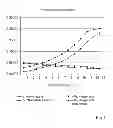
FIG. 1 is a graph of the performance parameters of the invented inspection system in terms of the numerical apertures on the object and image sides,
FIG. 2 is a graph of the illuminance in the image plane and the zoom factor V as a function of various zoom positions,
FIG. 3 illustrates the principle of a first exemplary embodiment,
FIG. 4 illustrates the principle of a second exemplary embodiment.
DETAILED DESCRIPTION OF THE DRAWINGS
FIG. 1 is a graph of the numerical apertures of the invented inspection system on the object and image sides as functions of imaging scale.
FIG. 2 shows the illuminance in the image plane and the zoom factor V as functions of the various zoom positions.
In the first exemplary embodiment shown in FIG. 3, the lens groups (LG1 through LG6) are designed according to the design data according to Table 1 below, which lists, starting on the object-side end, the consecutive numbers of the optically effective surfaces of the lenses within the lens groups, the radiuses of these surfaces, the distances between the surfaces, and the refractive indices and Abbe numbers of the lens materials used:
| TABLE 1 | ||||
| Refractive | Abbe | |||
| No. | Radius | Distance | index ne | number νe |
| 1 | 57.576 | 2.0 | 1.7254 | 34.47 |
| 2 | 37.013 | 7.0 | 1.5302 | 76.58 |
| 3 | 2214.3 | 0.1 | ||
| 4 | 74.931 | 6.5 | 1.7545 | 35.1 |
| 5 | 76.45 | variable | ||
| 6 | infinite | variable | ||
| 7 | −193.73 | 2.2 | 1.4879 | 76.58 |
| 8 | 24.019 | 5.23 | ||
| 9 | −77.997 | 1.8 | 1.6203 | 63.10 |
| 10 | 17.841 | 4.5 | 1.7254 | 34.47 |
| 11 | 65.137 | variable | ||
| 12 | 39.228 | 1.8 | 1.8063 | 29.6 |
| 13 | 25.976 | 7.0 | 1.4398 | 94.6 |
| 14 | −58.156 | 0.1 | ||
| 15 | 64.554 | 3.0 | 1.4398 | 94.6 |
| 16 | −172.37 | 0.3 | ||
| 17 | diaphragm | variable | ||
| 18 | −33.59 | 3.2 | 1.7254 | 34.47 |
| 19 | −14.935 | 1.5 | 1.6203 | 63.10 |
| 20 | 74.944 | variable | ||
| 21 | 555.55 | 3.0 | 1.4398 | 94.6 |
| 22 | −32.737 | 2.0 | 1.7584 | 34.47 |
| 23 | −53.246 | 71.5 | ||
| 24 | 35.563 | 10.28 | 1.6229 | 60.08 |
| 25 | −131.46 | 7.26 | 1.8083 | 46.25 |
| 26 | 34.476 | 9.2 | ||
| 27 | 88.532 | 8.15 | 1.6229 | 60.08 |
| 28 | −199.53 | |||
In this exemplary embodiment, the invented inspection system satisfies the following conditions:
Position of the object plane: 1 m to 5 m in front of the objective,
Position of the image plane: 150 mm behind the sixth lens group LG6,
Focusing distance (behind surface 5 in Table 1): 7.17 mm to 22.1 mm,
Movement range of the second lens group LG2 (surfaces 7 to 10 in Table 1): 0 mm to 55.2 mm,
Movement range of the fourth lens group LG4 (surfaces 18 to 20 in Table 1): 3 mm to 61.73 mm,
Distance between surfaces 6 and 12: 70.73 mm,
Distance between surfaces 17 and 21: 71.7 mm,
Image circle diameter: 23 mm,
Reciprocal magnification: −96 to −6 at the distance of 5 m between objective and object plane,
Image-side numerical aperture at minimum magnification β′: 0.05,
Image-side numerical aperture at maximum magnification β′: 0.025.
In the second exemplary embodiment shown in FIG. 4, are designed with design data according to Table 2 below, which lists, starting on the object-side end, the consecutive numbers of the optically effective surfaces of the lenses within the lens groups, the radiuses of these surfaces, the distances between the surfaces, and the refractive indices and Abbe numbers of the lens materials used:
| TABLE 2 | ||||
| Refractive | Abbe | |||
| No. | Radius | Distance | index ne | number νe |
| 1 | 105.075 | 8.50 | 1.5302 | 76.58 |
| 2 | −67.802 | 3.50 | 1.6588 | 39.46 |
| 3 | −190.197 | variable | ||
| 4 | infinite | variable | ||
| 5 | 116.315 | 2.50 | 1.4398 | 94.6 |
| 6 | 27.980 | 3.32 | ||
| 7 | −35.992 | 2.00 | 1.6940 | 54.48 |
| 8 | 18.836 | 3.80 | 1.7254 | 34.47 |
| 9 | 273.846 | variable | ||
| 10 | 29.853 | 4.90 | 1.4879 | 84.07 |
| 11 | −393.855 | 0.10 | ||
| 12 | 87.218 | 2.50 | 1.8881 | 40.52 |
| 13 | 20.982 | 4.80 | 1.4879 | 84.07 |
| 14 | −183.042 | 0.10 | ||
| 15 | 67.313 | 2.50 | 1.8881 | 40.52 |
| 16 | 1451.71 | 1.00 | ||
| 17 | diaphragm | variable | ||
| 18 | −45.316 | 3.80 | 1.7254 | 34.47 |
| 19 | −13.143 | 2.00 | 1.6808 | 54.92 |
| 20 | 50.479 | variable | ||
| 21 | 133.354 | 2.5 | 1.7434 | 32.0 |
| 22 | 79.34 | 3.2 | 1.4398 | 94.6 |
| 23 | −114.586 | 75.00 | ||
| 24 | 172.777 | 7.9 | 1.4879 | 84.07 |
| 25 | −43.089 | 3.5 | 1.5259 | 51.26 |
| 26 | −143.283 | |||
In this second exemplary embodiment, the invented inspection system satisfies the following conditions:
Position of the object plane: 1 m to 5 m in front of the objective,
Position of the image plane: 176.39 mm behind the sixth lens group LG6,
Focusing distance (surface 3 in Table 2): 4.31 mm to 26.7 mm,
Movement range of the second lens group LG2 (surfaces 5 to 9 in Table 2): 7.4 mm to 85.83 mm,
Movement range of the fourth lens group LG4 (surfaces 18 to 20 in Table 2): 3.36 mm to 47.89 mm,
Distance between surfaces 4 and 10: 99.45 mm,
Distance between surfaces 17 and 21: 57.30 mm,
Image circle diameter: 23 mm,
Reciprocal magnification: −89 to −5.56 at the distance of 5 m between objective and object plane,
Image-side numerical aperture at minimum magnification β′: 0.05,
Image-side numerical aperture at maximum magnification β′: 0.025.
Claims
1-13. (canceled)
14. An optical inspection system, designed for imaging an object to be inspected with a variable imaging scale, comprising
a variation system for imaging the object into infinity, the variation system consisting of, in order, a first lens group, a second lens group, a third lens group, a fourth lens group, and a fifth lens group, the first lens group being closest to the object, and the fifth lens group being furthest from the object;
a sixth lens group downstream of the variation system, for imaging the object from infinity into an image plane of an inspection system;
a light source for generating light in order to illuminate the object;
means for imaging the illuminating light into an exit pupil of the variation system in the air space between the fifth lens group and the sixth lens group; and
wherein the first, second and fourth lens groups are arranged so as to be movable along an optical axis, whereas the third and fifth lens groups are not movable.
15. The optical inspection system of claim 14, in which the first lens group includes a cemented doublet, the focal length of which is positive and between 160 mm and 125 mm long, and the free diameter of which is at least 40 mm, and in which the cemented doublet includes a collecting lens of fluor crown glass and a diverging lens of short flint glass.
16. The optical inspection system of claim 15, in which a zero-refraction meniscus is arranged downstream (in the direction of imaging) of the cemented doublet, the meniscus being convex on the object side.
17. The optical inspection system of claim 14, in which the second lens group has a negative focal length between 25.5 mm and 30.5 mm and its movement range along the optical axis is preferably twice as long as the amount of its focal length.
18. The optical inspection system of claim 14, in which the third lens group has a positive focal length between 43 mm and 44.5 mm and includes a plurality of collecting lenses, at least two of the collecting lenses consisting of fluor crown glass, with the third lens group being achromatically corrected.
19. The optical inspection system of claim 14, in which the fourth lens group has a negative focal length between 37 mm and 44 mm, includes a cemented doublet comprising a collecting lens of short flint glass, and has a movement range along the optical axis corresponding to 1.35 times the amount of its focal length.
20. The optical inspection system as claimed in of claim 14, in which an aperture diaphragm is provided between the fourth lens group and the fifth lens group.
21. The optical inspection system of claim 14, in which the fifth lens group has a positive focal length between 179 mm and 184 mm and includes a cemented doublet comprising a collecting lens of fluor crown glass and a diverging lens of short flint glass.
22. The optical inspection system of claim 14, in which the sixth lens group is a collecting, fully corrected, especially achromatized optical system with a light conductance of 1.15.
23. The optical inspection system of claim 14, in which the numerical aperture on the image side decreases with the fourth root of the zoom factor V, and in which the illumination only illuminates the pupil of the maximum magnification β′m, with the illuminance in the image plane decreasing with the square root of the zoom factor V.
24. The optical inspection system of claim 14, in which the first, second, third, fourth, fifth, and sixth lens groups are designed with design data according to the table below, which lists, starting on the object-side end, the consecutive numbers of the optically effective surfaces of the lenses within the lens groups, the radiuses of these surfaces, the distances between the surfaces, and the refractive indices and Abbe numbers of the lens materials used:
| Refractive | Abbe | |||
| No. | Radius | Distance | index ne | number νe |
| 1 | 57.576 | 2.0 | 1.7254 | 34.47 |
| 2 | 37.013 | 7.0 | 1.5302 | 76.58 |
| 3 | 2214.3 | 0.1 | ||
| 4 | 74.931 | 6.5 | 1.7545 | 35.1 |
| 5 | 76.45 | variable | ||
| 6 | infinite | variable | ||
| 7 | −193.73 | 2.2 | 1.4879 | 76.58 |
| 8 | 24.019 | 5.23 | ||
| 9 | −77.997 | 1.8 | 1.6203 | 63.10 |
| 10 | 17.841 | 4.5 | 1.7254 | 34.47 |
| 11 | 65.137 | variable | ||
| 12 | 39.228 | 1.8 | 1.8063 | 29.6 |
| 13 | 25.976 | 7.0 | 1.4398 | 94.6 |
| 14 | −58.156 | 0.1 | ||
| 15 | 64.554 | 3.0 | 1.4398 | 94.6 |
| 16 | −172.37 | 0.3 | ||
| 17 | diaphragm | variable | ||
| 18 | −33.59 | 3.2 | 1.7254 | 34.47 |
| 19 | −14.935 | 1.5 | 1.6203 | 63.10 |
| 20 | 74.944 | variable | ||
| 21 | 555.55 | 3.0 | 1.4398 | 94.6 |
| 22 | −32.737 | 2.0 | 1.7584 | 34.47 |
| 23 | −53.246 | 71.5 | ||
| 24 | 35.563 | 10.28 | 1.6229 | 60.08 |
| 25 | −131.46 | 7.26 | 1.8083 | 46.25 |
| 26 | 34.476 | 9.2 | ||
| 27 | 88.532 | 8.15 | 1.6229 | 60.08 |
| 28 | −199.53 | |||
25. The optical inspection system of claim 14, in which the first, second, third, fourth, fifth, and sixth lens groups are designed with design data according to the table below, which lists, starting on the object-side end, the consecutive numbers of the optically effective surfaces of the lenses within the lens groups, the radiuses of these surfaces, the distances between the surfaces, and the refractive indices and Abbe numbers of the lens materials used:
| Refractive | Abbe | |||
| No. | Radius | Distance | index ne | number νe |
| 1 | 105.075 | 8.50 | 1.5302 | 76.58 |
| 2 | −67.802 | 3.50 | 1.6588 | 39.46 |
| 3 | −190.197 | variable | ||
| 4 | infinite | variable | ||
| 5 | 116.315 | 2.50 | 1.4398 | 94.6 |
| 6 | 27.980 | 3.32 | ||
| 7 | −35.992 | 2.00 | 1.6940 | 54.48 |
| 8 | 18.836 | 3.80 | 1.7254 | 34.47 |
| 9 | 273.846 | variable | ||
| 10 | 29.853 | 4.90 | 1.4879 | 84.07 |
| 11 | −393.855 | 0.10 | ||
| 12 | 87.218 | 2.50 | 1.8881 | 40.52 |
| 13 | 20.982 | 4.80 | 1.4879 | 84.07 |
| 14 | −183.042 | 0.10 | ||
| 15 | 67.313 | 2.50 | 1.8881 | 40.52 |
| 16 | 1451.71 | 1.00 | ||
| 17 | diaphragm | variable | ||
| 18 | −45.316 | 3.80 | 1.7254 | 34.47 |
| 19 | −13.143 | 2.00 | 1.6808 | 54.92 |
| 20 | 50.479 | variable | ||
| 21 | 133.354 | 2.5 | 1.7434 | 32.0 |
| 22 | 79.34 | 3.2 | 1.4398 | 94.6 |
| 23 | −114.586 | 75.00 | ||
| 24 | 172.777 | 7.9 | 1.4879 | 84.07 |
| 25 | −43.089 | 3.5 | 1.5259 | 51.26 |
| 26 | −143.283 | |||
Images & Drawings included:


Sources:
- United States Patent and Trademark Office - verify current appl. status at the USPTO↗
Recent applications in this class:
- » 20250224598 2025-07-10
OPTICAL SYSTEM, LENS APPARATUS, AND IMAGE PICKUP APPARATUS - » 20250138291 2025-05-01
ZOOM OPTICAL SYSTEM - » 20250085518 2025-03-13
ZOOM OPTICAL SYSTEM, OPTICAL APPARATUS AND METHOD FOR MANUFACTURING THE ZOOM OPTICAL SYSTEM - » 20230176345 2023-06-08
Zoom optical system - » 20230008842 2023-01-12
PROJECTION SYSTEM AND METHOD WITH MODULAR PROJECTION LENS - » 20230003981 2023-01-05
SYSTEM AND METHOD FOR ELECTRONIC CORRECTION OF BORESIGHT ERRORS IN VARIABLE MAGNIFICATION OPTICAL SYSTEMS - » 20220299741 2022-09-22
OPTICAL SYSTEM, LENS APPARATUS, AND IMAGE PICKUP APPARATUS - » 20220099950 2022-03-31
Lens Device - » 20210349292 2021-11-11
Plastic barrel, autofocus module and electronic device - » 20200371323 2020-11-26
Camera and Lens Systems Using Off-Axis Free Form Elements and Methods Therefor
Recent applications for this Assignee:
- » 20250286724 2025-09-11
METHOD FOR AUTHENTICATING IMAGE DATA - » 20250285270 2025-09-11
VIRTUAL STAINING BASED ON MULTIPLE SETS OF IMAGING DATA HAVING MULTIPLE PHASE CONTRASTS - » 20250208396 2025-06-26
Microscope with fast quasi-confocal detection - » 20250199288 2025-06-19
Method for ascertaining offset values of an immersion objective of an image-creating optical system, and arrangement and computer program - » 20250157782 2025-05-15
METHOD FOR OPERATING A PARTICLE BEAM APPARATUS, COMPUTER PROGRAM PRODUCT AND PARTICLE BEAM APPARATUS FOR CARRYING OUT THE METHOD - » 20250157781 2025-05-15
METHOD FOR OPERATING A PARTICLE BEAM APPARATUS, COMPUTER PROGRAM PRODUCT AND PARTICLE BEAM APPARATUS FOR CARRYING OUT THE METHOD - » 20250111519 2025-04-03
INSTANCE SEGMENTATION USING OVERLAPPING TILES AND OVERLAP HANDLING - » 20250102788 2025-03-27
Microscopy System and Associated Methods - » 20250086945 2025-03-13
DIGITAL CONTRAST POST-PROCESSING OF MICROSCOPY IMAGES - » 20250078544 2025-03-06
CELL COUNTING OR CELL CONFLUENCE WITH RESCALED INPUT IMAGES