Buoyancy control material for subsea main pipelines and high-density buoyancy control material for subsea main pipelines
US20140018476A1
2014-01-16
13/817,139
2011-03-24
✅ Patent granted
US 8,895,642 B2
2014-11-25
WO; PCT/RU2011/000180; 20110324
WO; WO2012/078071; 20120614
Angela C Scott
Inventa Capital PLC
2031-03-24
Abstract:
The buoyancy control material for subsea main pipelines and high-density buoyancy control material for subsea main pipelines are suggested predominantly for use while manufacturing pipes for subsea pipeline installations. Creation of a buoyancy control material with a density greater than 2800 kg/m3 and the required mobility is an engineering problem solved by this invention. The buoyancy control material for subsea main pipelines contains cement, filler, plasticizing agent and water.
Inventors:
- Anatoly P. Svechkopalov 1 🇷🇺 Moscow, Russian Federation
- Igor I. Shaporin 1 🇷🇺 Moscow, Russian Federation
Applicant:
Interested in similar patents?
Get notified when new applications in this technology area are published.
Classification:
F16L1/24 » CPC main
Laying or reclaiming pipes; Repairing or joining pipes on or under water; Laying or reclaiming pipes on or under water; Accessories therefor, e.g. floats, weights Floats; Weights
C04B2111/2015 » CPC further
Mortars, concrete or artificial stone or mixtures to prepare them, characterised by specific function, property or use; Resistance against chemical, physical or biological attack Sulfate resistance
C04B28/04 » CPC further
Compositions of mortars, concrete or artificial stone, containing inorganic binders or the reaction product of an inorganic and an organic binder, e.g. polycarboxylate cements containing hydraulic cements other than calcium sulfates Portland cements
C04B2111/74 » CPC further
Mortars, concrete or artificial stone or mixtures to prepare them, characterised by specific function, property or use Underwater applications
C04B2111/0031 » CPC further
Mortars, concrete or artificial stone or mixtures to prepare them, characterised by specific function, property or use; Physical properties of the materials not provided for elsewhere in Heavy materials, e.g. concrete used as ballast material
C04B20/0076 » CPC further
Use of materials as fillers for mortars, concrete or artificial stone according to more than one of groups - and characterised by shape or grain distribution; Treatment of materials according to more than one of the groups - specially adapted to enhance their filling properties in mortars, concrete or artificial stone; Expanding or defibrillating materials characterised by the grain distribution
C04B24/223 » CPC further
Use of organic materials as active ingredients for mortars, concrete or artificial stone, e.g. plasticisers; Sulfur-containing compounds; Sulfonated aromatic compounds; Condensation or polymerisation products thereof Sulfonated melamine-formaldehyde condensation products
C04B24/2641 » CPC further
Use of organic materials as active ingredients for mortars, concrete or artificial stone, e.g. plasticisers; Macromolecular compounds obtained by reactions only involving carbon-to-carbon unsaturated bonds Polyacrylates; Polymethacrylates
C04B14/368 » CPC further
Use of inorganic materials as fillers, e.g. pigments, for mortars, concrete or artificial stone; Treatment of inorganic materials specially adapted to enhance their filling properties in mortars, concrete or artificial stone; Granular materials, e.g. microballoons; Inorganic materials not provided for in groups and - Baryte
C04B14/36 IPC
Use of inorganic materials as fillers, e.g. pigments, for mortars, concrete or artificial stone; Treatment of inorganic materials specially adapted to enhance their filling properties in mortars, concrete or artificial stone; Granular materials, e.g. microballoons Inorganic materials not provided for in groups and -
C04B2111/00482 » CPC further
Mortars, concrete or artificial stone or mixtures to prepare them, characterised by specific function, property or use; Uses not provided for elsewhere in Coating or impregnation materials
C04B2111/56 » CPC further
Mortars, concrete or artificial stone or mixtures to prepare them, characterised by specific function, property or use Compositions suited for fabrication of pipes, e.g. by centrifugal casting, or for coating concrete pipes
F16L58/06 » CPC further
Protection of pipes or pipe fittings against corrosion or incrustation by means of internal or external coatings; Coatings characterised by the materials used by cement, concrete, or the like
C04B2201/20 » CPC further
Mortars, concrete or artificial stone characterised by specific physical values for the density
C04B2201/50 » CPC further
Mortars, concrete or artificial stone characterised by specific physical values for the mechanical strength
F16L9/14 » CPC further
Rigid pipes Compound tubes, i.e. made of materials not wholly covered by any one of the preceding groups
C04B20/00 IPC
Use of materials as fillers for mortars, concrete or artificial stone according to more than one of groups - and characterised by shape or grain distribution; Treatment of materials according to more than one of the groups - specially adapted to enhance their filling properties in mortars, concrete or artificial stone; Expanding or defibrillating materials
C04B24/22 IPC
Use of organic materials as active ingredients for mortars, concrete or artificial stone, e.g. plasticisers; Sulfur-containing compounds; Sulfonated aromatic compounds Condensation or polymerisation products thereof
C04B24/26 IPC
Use of organic materials as active ingredients for mortars, concrete or artificial stone, e.g. plasticisers; Macromolecular compounds obtained by reactions only involving carbon-to-carbon unsaturated bonds
Description
PERTINENT ART
This invention is pertinent to pipeline equipment, specifically to buoyancy control materials applying on the outside pipe surface of subsea main pipelines to weight them down.
PRIOR KNOWLEDGE
The buoyancy control system for tubes including a buoyancy control material of a density equal to or greater than 2000 kg/m3 that comprises components as follows: cementing component, additive regulating the solidification time, fillers—water-sand mixture and/or water-barite mixture (U.S. Pat. No. 6,663,453, F16L 1/16, 09.01.2003), is known. The description of this patent does not disclose a component content of the buoyancy control material and a grain-size composition of fillers. The fact that acceptable density of buoyancy control material of present-day main pipelines is considerably higher than 2000 kg/m3 is a disadvantage of the known system.
Extra heavy concretes, among them barite concrete, a density of which exceeds 2500 kg/m3 (http://betony.ru), are known, but a composition of extra heavy concrete and details of its application as a buoyancy control material for tubes are not described in the abovementioned source.
The concrete comprising barite as a filler is referred to (WO 98/01402, C04B 14/36, 15.01.1998). To increase density, the filler has the predetermined grain-size composition, in which 8% wt (percents by weight) of barite are in the form of extra fine fraction having a particle size from 0.01 μm to 1000 μm, 4% wt in the form of fine fraction having a particle size from 1 mm to 3 mm, 10% wt in the form of coarse fraction having a particle size from 3 mm to 7 mm; fine silica sand having a grain size from 0.1 mm to 3 mm; coarse fraction of gravel from 3 mm to 75 mm. A water-cement ratio by mass is specified within the range from 0.30 to 0.35. Such composition has two major disadvantages: first—impossibility to obtain buoyancy control material with the guaranteed density exceeding 2800 kg/m3 due to lack of limitations by materials and their density for coarse and fine fillers; second—a small water-cement mass ratio in solution (from 0.30 to 0.35), that does not allow to use sluggish solution having coarse fractions to fill up the annulus between the conductive pipe and shell by injection through openings in lids.
The buoyancy control material for subsea main pipelines, that is the nearest analog of the claimed invention and contains cement, filler, plasticizing agent and water (RU 2257503, F16L 1/24, 27.07.2005), is known. This material is employed to form a layer of a buoyancy control material on a conductive pipe by filling in the annulus between the conductive pipe and shell of main pipelines and is the cement-sand solution with a mobility being sufficient to fill in the annulus between the conductive pipe and shell. The major drawback of the known material is its low density (up to 2400 kg/m3) generating a need to increase sizes of the buoyancy control material annulus to make a pipeline negatively buoyant.
DISCLOSURE OF INVENTION
The engineering problem solved by this invention is development of the buoyancy control material with a density greater than 2800 kg/m3 that has a compression strength reaching 50 MPa after hardening and ageing treatment within 28 days, that allows a significant reduction of the outside diameter of pipes with the ballasting coating.
This technical result is achieved by the reason that the buoyancy control material for subsea main pipelines comprises cement, filler, plasticizing agent and water. Sulfate-resisting portland cement is employed as a cement. Polycarboxylate-ester-based plasticizing agent is applied as a plasticizing agent. Barite middling product, barite ore and ferro-manganese concentrate are used as a filler of the material. The claimed material has a mixture ratio as follows, % wt: portland cement from 8.2 to 10.5, water from 5.2 to 6.7, plasticizing agent from 0.1 to 0.15, barite middling product from 15 to 20 having a density from 3.78 to 3.82 kg/cm3, barite ore from 15 to 20 having a density from 3.9 to 4.1 kg/cm3, ferro-manganese concentrate from 50 to 60 having a density from 4.2 to 4.5 kg/cm3. A water-portland cement ratio is within the range from 0.35 to 0.5. A grain-size composition of filler components in the claimed material is as follows: under 0.16 mm—up to 5%, from 0.16 to 1.0 mm—up to 25%, from 1.0 to 2.5 mm—up to 35%, from 2.5 to 5.0 mm—the rest.
A mixture ratio of the claimed material became available in the course of numerous natural experiments. Some results of them are given in Table 1. Addition of barite middling product to barite ore permits a considerable reduction of the buoyancy control material cost. A water-cement ratio selected within the range from 0.35 to 0.5 is needed to achieve the required mobility of the buoyancy control material.
A grain-size composition of the claimed material is given in Table 2. Selection of ratios is dictated by the necessity to achieve a buoyancy control material having the specified density. The density and compression strength of the suggested buoyancy control material can be found in the same table.
The claimed buoyancy control material enables to get the required density of extra heavy buoyancy control materials with a high accuracy within the range from 3350 to 3450 kg/m3.
The technical result is achieved as well by that the high-density buoyancy control material for subsea main pipelines contains cement, filler, plasticizing agent and water. In this case sulfate-resisting portland cement is employed as a cement. Barite ore and ferro-manganese concentrate are applied as a filler in the material. The claimed material has a mixture ratio as follows, % wt: portland cement from 9.2 to 10.5, water from 4.0 to 5.5, plasticizing agent from 0.05 to 0.18, barite ore from 3 to 17 having a density from 3.9 to 4.1 kg/cm3, ferro-manganese concentrate from 69 to 82 having a density from 4.2 to 4.5 kg/cm3. A water-portland cement ratio is within the range from 0.35 to 0.5. A grain-size composition of filler components makes up:
-
- under 0.16 mm—up to 3%,
- from 0.16 to 1.0 mm—up to 27%,
- from 1.0 to 2.5 mm—up to 34%,
- from 2.5 to 5.0 mm—the rest.
A complex additive consisting of all types of plasticizing agents with the following ratios, vol. % (percent by volume): plasticizing agent based on polycarboxylates and polyacrylic resins from 72 to 82;
plasticizing agent based on sulfonated naphthalene-formaldehyde polycondensates from 4 to 10;
plasticizing agent based on sulfonated melamine—formaldehyde polycondensates from 6 to 10;
plasticizing agent based on refined lignosulphates from 3 to 8;
-
- is employed as a plasticizing agent in the claimed material.
A mixture ratio of the claimed material was determined in the course of numerous natural experiments, some their results are given in Table 3.
A grain-size composition of the claimed material is presented in Table 4. Selection of ratios is dictated by the necessity to achieve a buoyancy control material having the specified high density. A density and compression strength of the suggested high density buoyancy control material is given in the same table.
The suggested buoyancy control material lets to get the required density of extra heavy buoyancy control materials with a high accuracy within the range from 3500 to 3700 kg/m3.
Use of ferro-manganese concentrate for both suggested buoyancy control materials is determined by two factors. First, ferro-manganese concentrate contains essential amount of oxide and hydroxide compounds of manganese, ferrum and other metals. Such compounds are good sulfur absorbents (absorbents for removal of sulphurated hydrogen from associated petroleum gas are made on their base). Sulfur is bound into complex compounds and consequently does not generate a negative impact on a reinforcing cage of a ballast layer and pipe body if the pipe has no insulating layer. Secondly, a high density of ferro-manganese concentrate enables to get extra heavy ballasting coating that in turn may lead to lowering the cost of the main pipe due to reduction of wall thickness.
CONCISE DESCRIPTION OF FIGURES TO DRAWINGS
The invention is illustrated by the drawings where the following is shown:
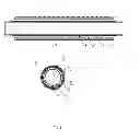
in FIG. 1—sectional views of a pipe having the ballasting coating made of a buoyancy control material with a polyurethane foam layer;
in FIG. 2—sectional views of a pipe having the ballasting coating made of a high-density buoyancy control material.
BEST MODE FOR CARRYING OUT INVENTION
A pipe exemplary embodiment comprising a buoyancy control material coating for subsea main pipelines is presented in FIG. 1. The presented embodiment has a central pipe 1 and support-and-guide unit composed of centralizers 2. Therewith the central pipe 1 may be coated with a polyethylene protective layer (is not shown on figures). A polyurethane foam layer 4 is applied between the central pipe 1 and a buoyancy control material 3. Centralizers 2 are distributed and fixed on the polyurethane foam layer 4. A reinforcing cage 5 is fixed on the polyurethane foam layer 4 by pins 6 and located inside the buoyancy control material 3, the external surface of which is formed by a shell 7. The reinforcing cage 5 consists of a longitudinal reinforcement 8, on which a lateral reinforcement 9 is reeled in a spiral pattern with an equal pitch.
While manufacturing the central pipe 1, a three-layer polyethylene coating is applied on its surface and is removed from ends of the central pipe. Then central pipe 1 is coated with the polyurethane foam layer 4.
Polyurethane foam has a very low heat-conductivity factor—0.05 W/(m*K) that in case of the layer thickness equal to 80 mm gives a heat-transfer resistance amounted to 1.6 (m*K)/W. Polyurethane foam is very resistant to environmental exposure, it has not been destroyed when exposed to ultraviolet light, salts, acids up to 10% and alkalies.
The reinforcing cage 5 is mounted of the longitudinal reinforcement 8, on which the lateral reinforcement 9 is reeled in a spiral pattern with an equal pitch on a separate stand. The longitudinal and lateral reinforcements 8 and 9 are connected by a binding wire and/or welding. The mounted reinforcing cage 5 is fixed on the polyurethane foam layer 4 by means of pins 6. After that centralizers 2 are assembled. The shell 7 is formed above the reinforcing cage 5. The shell 7 may have different configurations, that is depending on a structure of centralizers 2 a cross section of the shell 7 may have a square, rectangle, circular or elliptic shape. The shell 7 may be made of different materials (metal, metal-polymer, polymer). A material of the shell 7 is selected subject to operation conditions of the pipe with a ballasting coating.
The buoyancy control material 3 for subsea main pipelines is injected in the space between the external surface of the polyurethane foam layer 4 and the shell 7 by a concrete pump.
An exemplary embodiment of a pipe coated with a high-density buoyancy control material for subsea main pipelines is shown on FIG. 2. The given embodiment includes a central pipe 1 and support-and-guide unit consisting of centralizers 2. A mesh 10 is fixed by pins 6 and located inside of a buoyancy control material 3, the surface of that is formed by a shell 7.
While manufacturing the central pipe 1, a three-layer polyethylene coating is applied on its surface and is removed from ends of the central pipe.
Thereafter the mesh 10 is mounted and fixed on the central pipe 1 by pins 6, and centralizers 2 are assembled. The shell 7 is formed around the mesh 10 (metal, metal-polymer, polymer). The shell 7 may have different configurations, that is depending on a structure of centralizers 2, a cross section of the shell 7 may have a square, rectangle, circular or elliptic shape. A material of the shell 7 is selected subject to operation conditions of the pipe having a ballasting coating.
The high-density buoyancy control material 3 is injected in a space between the external surface of the central pipe 1 and shell 7.
A plasticizing agent is extremely important for extra heavy concretes. For the time being 4 basic types of plasticizing agents are employed: based on sulfonated naphthalene-formaldehyde polycondensates, based on sulfonated melamine—formaldehyde polycondensates, based on refined lignosulphates and based on polycarboxylates and polyacrylic resins. In spite of different type of effect on molecules, the essence of a plasticizing agent influence is confined to interaction of functional groups of a plasticizing agent with calcium hydroxide resulting in neutralization of molecules and their withdrawal from the surface of cement grains However analysis of interaction mechanics of different plasticizing agents suggests that an efficiency of a plasticizing agent is based on polycarboxylates and polyacrylic resins is tentatively twice as much as an efficiency of plasticizing agents based on sulfonated naphthalene-formaldehyde polycondensates and based on sulfonated melamine—formaldehyde polycondensates and is almost thrice as much as an efficiency of plasticizing agents based on refined lignosulphates. Against this background a plasticizing agent in the form of the complex additive consisting of all types of plasticizing agents is employed in the given embodiment in the following ratios (vol. %): plasticizing agent based on polycarboxylates and polyacrylic resins from 72 to 82%, plasticizing agent based on sulfonated naphthalene-formaldehyde polycondensates from 4 to 10%, plasticizing agent based on sulfonated melamine—formaldehyde polycondensates from 6 to 10% and plasticizing agent based on refined lignosulphates from 3 to 8%.
Using a plasticizing agent in the form of the complex additive enables to achieve such mobility of the high-density buoyancy control material 3 which allows it to flow easily around such obstacles as centralizers 2 and pins 6. The buoyancy control material 3 has sufficient mobility to fill in all the space regardless a form of the shell cross section.
The buoyancy control material 3 solidifies within 3-3.5 hours. After that the construction has been left for 10-12 hours at +15 . . . +20° C. temperature to gain in strength of the buoyancy control material within the range from 3 to 5 MPa. The buoyancy control material has been gained in strength within the range from 3 to 20 MPa after laying the pipe having a ballasting coating on a sand cushion.
INDUSTRIAL APPLICABILITY
The claimed buoyancy control material for subsea main pipelines and high-density buoyancy control material for subsea main pipelines permits to manufacture pipes having a ballasting coating which are stronger, more heat-resistant and have an extended service life. Pipes with the claimed coating have a higher cross-breaking strength and may be used in installations of subsea pipelines to lay them in a variety of climatic conditions.
| TABLE 1 | |||
| Composition | |||
| Composition | Composition | by the | |
| Components | No. 1 | No. 2 | original |
| Cement, kg/m3 | 340 | 350 | 420 |
| Water, kg/m3 | 150 | 150 | 140 |
| Polycarboxylate-ester- | 2.4 | 2.4 | — |
| based plasticizing agent, | |||
| kg/m3 | |||
| Barite middling product, | 960 | 700 | — |
| kg/m3 | |||
| Gravel | — | — | 840 |
| Barite ore, kg/m3 | 980 | 700 | 430 |
| Ferro-manganese | 950 | 1550 | — |
| concentrate, kg/m3 | |||
| Sand | — | — | 650 |
| Density, kg/m3 | 3390 | 3450 | 2480 |
| Compression strength, | 48 | 47 | 45 |
| MPa | |||
| TABLE 2 | ||
| Density | Grain-size composition, | |
| Component name | kg/cm3 | mm |
| Barite middling product | from 3.78 to 3.82 | up to 5%; |
| from 0.16 to 1.0 up to 25% | ||
| from 1.0 to 2.5 up to 35% | ||
| from 2.5 to 5.0 the rest | ||
| Barite ore | from 3.9 to 4.1 | up to 5%; |
| from 0.16 to 1.0 up to 25% | ||
| from 1.0 to 2.5 up to 35% | ||
| from 2.5 to 5.0 the rest | ||
| Ferro-manganese | from 4.2 to 4.5 | up to 5%; |
| concentrate | from 0.16 to 1.0 up to 25% | |
| from 1.0 to 2.5 up to 35% | ||
| from 2.5 to 5.0 the rest | ||
| TABLE 3 | ||||
| Com- | Com- | Composition | ||
| Composition | position | position | by the | |
| Components | No. 1 | No. 2 | No. 3 | original |
| Cement, kg/m3 | 360 | 360 | 360 | 420 |
| Water, kg/m3 | 150 | 150 | 150 | 140 |
| Plasticizing agent, | 4 | 5 | 6 | — |
| kg/m3 | ||||
| Gravel | — | — | — | 840 |
| Barite ore, kg/m3 | 550 | 350 | 120 | 430 |
| Ferro-manganese | 2490 | 2750 | 3080 | — |
| concentrate, kg/m3 | ||||
| Sand | — | — | — | 650 |
| Density, kg/m3 | 3500 | 3600 | 3700 | 2480 |
| Compression strength, | 48 | 48 | 47 | 45 |
| MPa | ||||
| TABLE 4 | |||
| Density | Grain-size composition, | ||
| Component name | kg/cm3 | mm. | |
| Barite ore | from 3.9 to 4.1 | up to 3%; | |
| from 0.16 to 1.0 up to 27% | |||
| from 1.0 to 2.5 up to 34% | |||
| from 2.5 to 5.0 the rest | |||
| Ferro-manganese | from 4.2 to 4.5 | up to 3%; | |
| concentrate | from 0.16 to 1.0 up to 27% | ||
| from 1.0 to 2.5 up to 34% | |||
| from 2.5 to 5.0 the rest | |||
Claims
1. (canceled)
2. (canceled)
3. (canceled)
4. The buoyancy control material for subsea main pipelines, said material comprising:
a cement,
a filler,
a plasticizing agent,
a water, wherein said cement is further defined by a sulfate-resisting portland cement, said plasticizing agent is further defined by a polycarboxylate-ester-based plasticizing agent, and said filler is further defined by at least one of barite middling product, barite ore, and ferro-manganese concentrate having a component ratio as follows, % wt: said portland cement from 8.2 to 10.5, said water from 5.2 to 6.7, said plasticizing agent from 0.1 to 0.15.
5. The buoyancy control material as set forth in claim 4, wherein said barite middling product ranges from 18 to 28 having a density from 3.78 to 3.82 kg/cm3, said barite ore ranges from 18 to 28 having a density from 3.9 to 4.1 kg/cm3, said ferro-manganese concentrate ranges from 25 to 45 having a density from 4.2 to 4.5 kg/cm3 presenting a water-portland cement ratio within the range from 0.35 to 0.5 and a grain-size composition of filler components as follows:
under 0.16 mm and up to 5%,
from 0.16 to 1.0 mm and up to 25%,
from 1.0 to 2.5 mm and up to 35%
from 2.5 to 5.0 mm and the rest.
6. The high-density buoyancy control material for subsea main pipelines, comprising:
a cement,
a filler,
a plasticizing agent,
a water, wherein said cement is further defined by a sulfate-resisting portland cement, barite ore and ferro-manganese concentrate are used as a filler having a component ratio as follows, % wt:
| portland cement | from 9.2 to 10.5. | |
| water | from 4.0 to 5.5. | |
| plasticizing agent | from 0.05 to 0.18. | |
barite ore from 3 to 17 having a density from 3.9 to 4.1 kg/cm3,
ferro-manganese concentrate from 69 to 82 having a density from 4.2 to 4.5 kg/cm3,
with a water-portland cement ratio from 0.35 to 0.5
and a grain-size composition of filler components as follows:
from 0.16 mm—up to 3%,
from 0.16 to 1.0 mm—up to 27%,
from 1.0 to 2.5 mm—up to 34%
from 2.5 to 5.0 mm—the rest.
7. The high-density buoyancy control material as set forth in claim 6 further including a complex additive having said plasticizing agents with a ratio as follows, vol. %: a plasticizing agent based on polycarboxylates and polyacrylic resins ranging from 72 to 82; a plasticizing agent based on sulfonated naphthalene-formaldehyde polycondensates ranging from 4 to 10; a plasticizing agent based on sulfonated melamine—formaldehyde polycondensates ranging from 6 to 10; a plasticizing agent based on refined lignosulphates ranging from 3 to 8.
Images & Drawings included:


Sources:
- United States Patent and Trademark Office - verify current appl. status at the USPTO↗
Recent applications in this class:
- » 20240369160 2024-11-07
SYSTEMS AND METHODS FOR CABLE INSTALLATION - » 20230332718 2023-10-19
A FLOATING PIPE COMPRISING A TUBE AND A FLOATER SURROUNDING SAID TUBE - » 20230279969 2023-09-07
BUOYANCY MODULE - » 20230057030 2023-02-23
Apparatus, system and method for joining elongated elements in a body of water - » 20210301946 2021-09-30
METHOD FOR CONTROLLING BUCKLING IN DEEPWATER PIPELINE WITH BUOYANCY MODULES - » 20200362991 2020-11-19
Device for the transfer of cryogenic products between a floating structure and a fixed or floating structure - » 20190346068 2019-11-14
Controlling buoyancy when towing, lowering and raising submerged structures - » 20180306347 2018-10-25
Pipe-clamping block - » 20180252334 2018-09-06
Clamp assembly - » 20180195644 2018-07-12
SUPPORT DEVICE FOR AT LEAST ONE PORTION OF A LINEAR STRUCTURE FOR CROSSING AN UNEVEN UNDERWATER TOPOGRAPHY, ASSEMBLY COMPRISING SAID DEVICE AND METHOD OF SUPPORT