Magnet valve for controlling a fluid
US20140027658A1
2014-01-30
13/984,049
2011-12-15
✅ Patent granted
US 9,133,957 B2
2015-09-15
WO; PCT/EP2011/072912; 20111215
WO; WO2012/107137; 20120816
John Bastianelli
Maginot Moore & Beck LLP
2032-01-18
Abstract:
A magnet valve configured to control a fluid includes an armature with a base region, a casing region, and a head region. The magnet valve also includes a valve element that is connected to the armature and an armature housing component. A flow path is formed between the armature and the armature housing component. The flow path runs from a lower armature chamber to an upper armature chamber and back to the lower armature chamber. The head region of the armature has a flattened section, and the upper armature chamber is defined between the armature housing component and the flattened section. At least one groove is formed on the casing region of the armature starting from the base region. The at least one groove ends in the casing region before the flattened section of the head region.
Inventors:
- Andreas Karl 8 🇩🇪 Benningen/Neckar, Germany
- Stephan Steingass 8 🇩🇪 Bornheim, Germany
- Elmar Vier 10 🇩🇪 Freiberg A.N., Germany
- Nicolas Houis 15 🇩🇪 Bietigheim-Bissingen, Germany
- Massimiliano Ambrosi 9 🇩🇪 Benningen, Germany
- Andreas Karl 1 🇩🇪 Benningen/Necke, Germany
- Elmar VIER 8 🇩🇪 Freiberg A. N., Germany
- Jens Norberg 12 🇩🇪 Stuttgart, Germany
- Andreas Lechler 10 🇩🇪 Moeglingen, Germany
- Gerhard Stokmaier 6 🇩🇪 Markgroeningen, Germany
Assignee:
- Robert Bosch GMBH 19,123 🇩🇪 Stuttgart, Germany
- ROBERT BOSCH GMBH 103 🇺🇸 Stuttgart, DE, United States
Applicant:
Interested in similar patents?
Get notified when new applications in this technology area are published.
Classification:
F16K31/08 » CPC main
Operating means Actuating devices; ; Releasing devices electric ; magnetic using a magnet, e.g. diaphragm valves, cutting off by means of a liquid using a permanent magnet
B60T8/363 » CPC further
Arrangements for adjusting wheel-braking force to meet varying vehicular or ground-surface conditions, e.g. limiting or varying distribution of braking force responsive to a speed condition, e.g. acceleration or deceleration having a fluid pressure regulator responsive to a speed condition including a pilot valve responding to an electromagnetic force; Electromagnetic valves specially adapted for anti-lock brake and traction control systems in hydraulic systems
B60T13/686 » CPC further
Transmitting braking action from initiating means to ultimate brake actuator with power assistance or drive; Brake systems incorporating such transmitting means, e.g. air-pressure brake systems with fluid assistance, drive, or release; Electrical control in fluid-pressure brake systems by electrically-controlled valves in hydraulic systems or parts thereof
B60T15/028 » CPC further
Construction arrangement, or operation of valves incorporated in power brake systems and not covered by groups or; Application and release valves; Electrically controlled valves in hydraulic systems
F16K31/0696 » CPC further
Operating means Actuating devices; ; Releasing devices electric ; magnetic using a magnet, e.g. diaphragm valves, cutting off by means of a liquid; Braking, pressure equilibration, shock absorbing Shock absorbing, e.g. using a dash-pot
B60T8/36 IPC
Arrangements for adjusting wheel-braking force to meet varying vehicular or ground-surface conditions, e.g. limiting or varying distribution of braking force responsive to a speed condition, e.g. acceleration or deceleration having a fluid pressure regulator responsive to a speed condition including a pilot valve responding to an electromagnetic force
B60T13/68 IPC
Transmitting braking action from initiating means to ultimate brake actuator with power assistance or drive; Brake systems incorporating such transmitting means, e.g. air-pressure brake systems with fluid assistance, drive, or release; Electrical control in fluid-pressure brake systems by electrically-controlled valves
B60T15/02 IPC
Construction arrangement, or operation of valves incorporated in power brake systems and not covered by groups or Application and release valves
F16K31/06 IPC
Operating means Actuating devices; ; Releasing devices electric ; magnetic using a magnet, e.g. diaphragm valves, cutting off by means of a liquid
Description
The present invention concerns a normally closed magnet valve for controlling a fluid.
Such normally closed magnet valves for controlling a fluid are known from the prior art in various embodiments, in particular for example as outlet valves for antilock, traction and stability devices (ABS/TCS/ESP devices) in motor vehicles. These magnet valves have an armature which is arranged axially moveable in a valve housing. In certain operating ranges, because of the vibrations occurring, the magnet valves tends to produce undesirable noise effects due to the axial knocking of the armature on the valve housing.
DISCLOSURE OF THE INVENTION
The magnet valve according to the invention for controlling a fluid with the features of claim 1 in contrast has the advantage that the tendency to vibration is substantially reduced by shaping of the armature. This is achieved according to the invention in that the magnet valve comprises an armature with a base region, a casing region and a head region, a valve element connected with the armature, and an armature housing component. Between the armature and the armature housing component here is formed a flow path which runs from a lower armature chamber to an upper armature chamber and back to the lower armature chamber. The head region has a flattened section, wherein the upper armature chamber is defined between the armature housing component and the flattened section. At least one groove is formed in the casing region of the armature, starting from the base region, which groove ends in the casing region before the flattened section of the head region. Thus on reset of the armature, a damping effect is achieved by the fluid in the upper armature chamber which significantly improves the hydraulic damping behavior of the magnet valve and guarantees reliable operating function with a significantly reduced noise development of the magnet valve.
The subclaims indicate preferred refinements of the invention.
According to a preferred embodiment of the invention, a transition region is arranged between the casing region and the head region, wherein the groove ends in the transition region. Further preferably the groove starting from the casing region ends in the first third of the transition region. Because of the targeted geometric design and the resulting effective flow cross sections between armature and armature housing component, a significantly improved hydraulic damping of the armature is achieved. The extent of hydraulic damping here depends on the selected geometric sizes of the differential cross section, the moistened periphery and the gap geometry/length.
Preferably a second groove is provided which lies opposite the first groove. This achieves a widened flow path with improved flow between the upper and lower armature chambers. The result is a reduction of the pressure predominating in the flow path and an increased flow speed, whereby a low-resistance flow course is achieved.
In a further advantageous embodiment of the invention the armature has a bell shape which promotes a present, low-resistance flow course from the lower armature chamber to the upper armature chamber and back to the lower armature chamber, and thus gives the armature a high strength with a high cold-forming capacity. Furthermore the armature housing component has a pot-like shape, from which a compact construction results with low installation volume which facilitates installation in the magnet valve.
According to a preferred embodiment of the invention, the armature has a second transition region which is arranged on the casing region. In a further advantageous embodiment of the invention the second transition region provides a stop on the armature housing component. On movement of the armature to the stop, a progressive gradation of the hydraulic damping is hereby achieved over the armature stroke, which rises until reaching the maximum stroke and particularly effectively damps the mechanical impact. Thus a noise development which is unacceptable for various applications can be avoided. The magnet valve can preferably be used as a control/outlet valve in antilock, traction and stability devices (ABS/TCS/ESP devices).
BRIEF DESCRIPTION OF THE DRAWING
Embodiment examples of the invention are described in detail below with reference to the enclosed drawing. In the drawing:
FIG. 1 shows a diagrammatic section view of an armature of a magnet valve for controlling a fluid according to a first embodiment example of the invention;
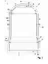
FIG. 2 shows a perspective view of the armature of the magnet valve of FIG. 1, and
FIG. 3 shows a diagrammatic section view of an armature of a magnet valve for controlling a fluid according to a second embodiment example of the invention.
EMBODIMENTS OF THE INVENTION
With reference to FIGS. 1 and 2, a magnet valve for controlling a fluid according to a first preferred embodiment example of the invention is described in detail below.
FIG. 1 shows a diagrammatic section view of an armature 2 of a magnet valve 1 for controlling a fluid according to the first embodiment example of the invention.
As evident from FIG. 1, the armature 2 has a base region 20, a casing region 21 and a head region 22 and is connected at the base region 20 with a valve element 3 of the magnet valve 1. The armature 2 is accommodated in an armature housing component 23. Between the armature 2 and the armature housing component 23 is formed a flow path 26. A flow course in the flow path 26 is marked with arrows P1, P2 and P3 and runs from a lower armature chamber 24 to an upper armature chamber 25 and back to the lower armature chamber 24. The head region 22 has a flattened section 32, wherein the upper armature chamber 25 is defined between the armature housing component 23 and the flattened section 32. A groove 28 is formed in the casing region 21 of the armature 2, starting from the base region 20. The groove 28 is for example formed as a V-groove with a base region 30. Between the head region 22 and the casing region 21 of the armature 2 is furthermore arranged a first transition region 27. As further evident from FIG. 1, the groove 28 ends in the transition region 27 before the flattened section 32 of the head region 22, preferably in the first third of the transition region 27.
As evident from FIG. 2, the armature 2 has a bell shape with the head region 22, the first transition region 27, a first casing region 21a, a second transition region 37, a second casing region 21b and the base region 20. The second casing region 21b here has a maximum diameter D2 which is greater than a maximum diameter D1 of the first casing region 21a (cf. FIG. 1). Also because of its tapering outer surface, the second transition region 37 provides a stop A on the armature housing component 23 (cf. FIG. 1). The shaping promotes a present, low-resistance flow course in the flow path 26 between the armature 2 and the armature housing component 23. Furthermore the armature 2 as a result has a particularly compact construction with minimum construction volume. Also a progressively rising hydraulic damping over the armature stroke is achieved, which on reaching the maximum stroke effectively damps the mechanical impact with substantially reduced noise development.
FIG. 3 shows a diagrammatic section view of the armature 2 of the magnet valve 1 according to a second embodiment example, wherein the same components or those with the same function carry the same reference numerals as in the first embodiment example.
In contrast to the first embodiment example, in this second embodiment example the armature 2 has a second groove 29 which is arranged opposite the first groove 28. Thus the flow path 26 is substantially widened between the armature housing component 23 (not shown here) and the armature 2, between the lower armature chamber 24 and the upper armature chamber 25, and a perceptibly improved flow through the armature 2 is achieved as the main part of the flow takes place through the grooves 28, 29.
The magnet valve 1 according to the invention in the embodiment examples described above has the advantage that by corresponding shaping or by the outer form of the armature 2, the susceptibility to vibration and the hydraulic damping are substantially improved. As well as a substantially reduced noise development, furthermore an improvement in the electromagnetic curve of the magnet valve 1 results therefrom which guarantees a more precise function accuracy of the magnet valve 1 in all operating points.
Claims
1. A magnet valve for controlling a fluid, comprising:
an armature with a base region, a casing region and a head region;
a valve element connected with the armature; and
an armature housing component,
wherein a flow path formed between the armature and the armature housing component is configured to run from a lower armature chamber to an upper armature chamber and back to the lower armature chamber,
wherein the head region has a flattened section,
wherein the upper armature chamber is defined between the armature housing component and the flattened section,
wherein at least one groove formed on the casing region of the armature, is configured to start from the base region, and
wherein the at least one groove is configured to end in the casing region before the flattened section of the head region.
2. The magnet valve as claimed in claim 1, further comprising a transition region arranged between the casing region and the head region, the at least one groove configured to end in the transition region.
3. The magnet valve as claimed in claim 2, wherein the at least one groove is configured to start from the casing region and end in a first third of the transition region.
4. The magnet valve as claimed in claim 1, wherein the at least one groove includes a second groove configured to lie opposite a first groove.
5. The magnet valve as claimed in claim 1, wherein the armature has a bell shape and the armature housing component has a pot-like shape.
6. The magnet valve as claimed in claim 1, wherein the at least one groove is a V-groove with a base region.
7. The magnet valve as claimed in claim 1, further comprising a second transition region arranged on the casing region.
8. The magnet valve as claimed in claim 7, wherein the second transition region is configured to provide a stop on the armature housing component.
Images & Drawings included:


Sources:
- United States Patent and Trademark Office - verify current appl. status at the USPTO↗
Similar patent applications:
- » 10849940
Magnetically-actuated fluid control valve - » 20230194067
Magnetically controlled fluid drain valve for aircraft exterior light unit - » 10374206
Gas pressure driven fluid pump having magnetic valve control mechanism and method - » 20230136072
Valve and fluid control device with a magnetic indicator
Recent applications in this class:
- » 20250035232 2025-01-30
AUTOMATIC MAGNETIC VALVE, SYSTEM, AND METHODS - » 20240295276 2024-09-05
VALVE - » 20210156490 2021-05-27
Magnetic actuator, system and method - » 20200284374 2020-09-10
Magnetically coupled actuator and lead screw control for a variable pressure pilot valve - » 20190353271 2019-11-21
Electric valve - » 20190285193 2019-09-19
Valve actuator, valve, and machine consisting thereof - » 20190226599 2019-07-25
Fluid routing device having a valve with first and second permanent magnets - » 20190032809 2019-01-31
Solenoid controlled valve assembly including a poppet and diaphragm - » 20150204455 2015-07-23
Grid valve apparatus - » 20150115183 2015-04-30
System for adjusting water in a shower, bathroom, or kitchen sink
Recent applications for this Assignee:
- » 20250154889 2025-05-15
PRESSURE CONTROL IN AN EXHAUST AFTERTREATMENT SYSTEM - » 20250154580 2025-05-15
ENZYME TRANSLOCATORS IN NANOGAP WITH 3' -ESTERS - » 20250147582 2025-05-08
METHOD FOR DETERMINING AN EYE DISTANCE IN A PAIR OF DATA GLASSES, AND DATA GLASSES - » 20250146568 2025-05-08
DRIVE ASSEMBLY AND VEHICLE HAVING SUCH A DRIVE ASSEMBLY - » 20250146495 2025-05-08
Flexible Pump Assembly for Use in a Fan Drive - » 20250140882 2025-05-01
FUEL CELL SYSTEM HAVING ENERGY RECUPERATION - » 20250137810 2025-05-01
METHOD FOR MATCHING A DIGITAL ROAD MAP - » 20250137033 2025-05-01
DNA UNFOLDING USING A FREE-END TAG FLOW MODIFIER - » 20250119751 2025-04-10
A BLUETOOTH COMMUNICATION METHOD AND SYSTEM - » 20250118116 2025-04-10
Diagnostic Protocol Search With Improved Efficiency