Snap-fit separable mobile backup power supply
US20140028258A1
2014-01-30
13/994,983
2012-02-20
✅ Patent granted
US 9,203,250 B2
2015-12-01
WO; PCT/CN2012/000213; 20120220
WO; WO2013/123613; 20130829
Sun Lin
Jeanette Meng Nakagawa
2032-06-24
Abstract:
The power supply also includes battery charging module and engaging means, the module includes a bottom cover, isolation plate and a circuit board, the isolation plate with fixed bottom cover, the circuit board connected to the battery, the bottom have a cavity to receive battery and circuit board, the isolation plate installed in the circuit board and the top of the battery, the circuit board has to match the terminal, above the terminal is equipped with the terminal cover, the terminal cover and isolation plate fixing.
Since the protective sleeve and bottom cover is fixed, power while matching with mobile phone connected to terminal, on the one hand you can charge the phone from the power to extend the phone's standby time or use, Use the cable is not required to use any user-friendly, compact structure, small size, easy to carry user; Hand side protective sleeve and bottom but will be separated, user need to select personalized protective sleeve color.
Applicant:
Interested in similar patents?
Get notified when new applications in this technology area are published.
Classification:
H02J7/0042 » CPC main
Circuit arrangements for charging or depolarising batteries or for supplying loads from batteries characterised by the mechanical construction
H02J7/00 IPC
Circuit arrangements for charging or depolarising batteries or for supplying loads from batteries
H04M1/0262 » CPC further
Substation equipment, e.g. for use by subscribers; Constructional features of telephone sets; Portable telephone sets, e.g. cordless phones, mobile phones or bar type handsets; Details of the structure or mounting of specific components for a battery compartment
H04M1/0283 » CPC further
Substation equipment, e.g. for use by subscribers; Constructional features of telephone sets; Portable telephone sets, e.g. cordless phones, mobile phones or bar type handsets; Improving the user comfort or ergonomics for providing a decorative aspect, e.g. customization of casings, exchangeable faceplate
H04M1/02 IPC
Substation equipment, e.g. for use by subscribers Constructional features of telephone sets
Description
TECHNICAL FIELD
The invention relates to power technology field, especially relates to detachable phone power supply.
BACKGROUND OF THE INVENTION
As technology advances, personal consumer electronics and more powerful features, such as smart phones, although it can provide people with more convenience and choice, smartphones although more powerful, but it needs to provide greater capacity batteries, otherwise the phone comes with a battery is easy to run out, can not provide sufficient long life, resulting in possible emergency rechargeable battery to charge the battery.
Current power source is usually separated from mobile phone, only will be connected to the power supply when using mobile phone, it will bring inconvenience to users. At the same time, the appearance of the smartphone to make more and more exquisite, electronic components has become increasingly sophisticated, its function is getting stronger and stronger. User during use to prevent scratches smart phone shell and reduce the impact force influence the reliability of smart phones, so smart phones usually smartphone needs to set up a case, because the smart phone cases do not have the power, and therefore not smart phones to charge their phone. Back at the same time, mobile power supply or future use power often cannot for smart phones, and in the use of mobile power source or standby back need through the cable connected with the power process, which brings convenience to use and carry.
BRIEF SUMMARY OF EMBODIMENTS OF THE INVENTION
Technical problems solved by this invention is to provide detachable phone power supply, the power supply can provide a long time in power for communication terminal, extend the battery life of communication terminal, the power supply compact structure, easy to use and carry
In order to solve the above problem, the present invention provides detachable phone power supply, the power supply including the protection sleeve, the power supply also includes battery charging module and engaging means, the module includes a bottom cover, isolation plate and a circuit board, the isolation plate with fixed bottom cover, the circuit board connected to the battery, the bottom have a cavity to receive battery and circuit board, the isolation plate installed in the circuit board and the top of the battery, the circuit board has to match the terminal, above the terminal is equipped with the terminal cover, the terminal cover and isolation plate fixing.
Preferably, the engaging means including hasp, the hasp activities connected with the bottom cover, the protection sleeve have embossment or grooves, the embossment or grooves with the hasp to cooperate with.
Preferably, the engaging means including strips and at least two grooves, the strips in protective sleeve and groove fit.
Preferably, the engaging means including snapping feature, the parts set in an isolated plate or bottom, the parts cooperate with fixed hole.
Preferably, the parts sectional view along the centerline was T-shaped, the fixed hole shape for 8 word or hoist type, the fixed hole on one side to the step structure.
Preferably, the bottom cover is also a fixed buckle.
Preferably, the circuit board is also a charging terminals and keys.
Preferably, the terminal cover terminal cover has a transparent film, the translucent sheet through the button on the handle and key contacts of the circuit board.
The power supply also includes battery charging module and engaging means, the module includes a bottom cover, isolation plate and a circuit board, the isolation plate with fixed bottom cover, the circuit board connected to the battery, the bottom have a cavity to receive battery and circuit board, the isolation plate installed in the circuit board and the top of the battery, the circuit board has to match the terminal, above the terminal is equipped with the terminal cover, the terminal cover and isolation plate fixing.
Since the protective sleeve and bottom cover is fixed, power while matching with mobile phone connected to terminal, on the one hand you can charge the phone from the power to extend the phone's standby time or use, Use the cable is not required to use any user-friendly, compact structure, small size, easy to carry user; Hand side protective sleeve and bottom but will be separated, user need to select personalized protective sleeve color.
BRIEF DESCRIPTION OF THE DRAWINGS
In order to more clearly illustrate embodiments of the invention or the prior art technical solutions, following the embodiments described in the prior art, or the accompanying drawings required for a brief introduction Apparently, while the description of the drawings is some embodiments of the invention, those of ordinary skill in the premise without creative efforts, you can also obtain other drawings based on these drawings.
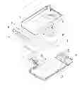
FIG. 1 embodiment of the present invention the power supply breakdown structure diagram.
FIG. 2 is part of the structure B in FIG. 1 is an enlarged schematic view.
FIG. 3 is part of the structure A in FIG. 1 is an enlarged schematic view.
FIG. 4 is a fixed enlarged schematic view of the structure of the battery components.
FIG. 5 is another embodiment of the engaging means schematic.
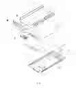
FIG. 6 is a schematic structural view of another embodiment of the power supply.
FIG. 7 is a direction along the C-C cross-sectional schematic.
FIG. 8 is a direction along the D-D cross-sectional schematic.
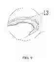
FIG. 9 is a part of the structure E in FIG. 6.
DETAILED DESCRIPTION OF THE EMBODIMENTS OF THE INVENTION
To object of the invention to make technical solutions and advantages become more apparent, the following embodiments of the invention in conjunction with the accompanying drawings, embodiments of the present invention, the technical solutions clearly and completely described, obviously, the described embodiments are invention, part of the embodiments, but not all embodiments. Based on the embodiment of the present invention, persons of ordinary skill in the art without creative efforts obtained under the premise that all other embodiments, all belong to the protection scope of the present invention.
Shown in FIG. 1, the present invention provides the power supply embodiments.
The power supply including a protection sleeve 1, the power supply also includes battery charging module and engaging means, the module includes a bottom cover 2, isolation plate 5 and a circuit board 4, the isolation plate 5 with fixed bottom cover 2, the circuit board 4 connected to the battery 3, the bottom cover 2 have a cavity 21 to receive battery 3 and circuit board 4, the isolation plate 5 installed in the circuit board 4 and the top of the battery 3, the circuit board 4 has to match the terminal 41, above the terminal 41 is equipped with the terminal cover 7, the terminal cover 7 and isolation plate 5 fixing.
Specifically, the circuit board 4 is provided for power charging terminals 41 and keys, the terminals 41 can be convenient for the user when the battery is dead can not recharge, said key 41 can operate the buttons on the phone.
The terminal cover 7 is provided with transparent film 6, the transparent sheet 6 through 8 and the circuit board shank buttons 4 buttons on (photos not labeled) contacts. The transparent film 6 is PVC film, with its double-sided adhesive through the terminal cover 7 is fixed, translucent sheet 6 can be better through the lights on the circuit board 4, user-friendly operation.
As shown in FIG. 2 and FIG. 3, the engaging means including hasp 27, the hasp activities connected with the bottom cover 2, the protection sleeve 1 have embossment or grooves 16, the embossment or grooves 16 with the hasp 27 to cooperate with. When the phone needs charging, the battery charging module through the engaging means engaging with the protective cover a fixed charge the battery module and work closely with a protective sleeve fixed, the phone can charge the battery module via terminal 41 and battery connection to charging. Without charge the phone, you can charge the battery module with a separate protective sleeve.
Since the protective sleeve and bottom cover is fixed, power while matching with mobile phone connected to terminal, on the one hand you can charge the phone from the power to extend the phone's standby time or use, Use the cable is not required to use any user-friendly, compact structure, small size, easy to carry user; Hand side protective sleeve and bottom but will be separated, user need to select personalized protective sleeve color.
As shown in FIG. 4, the bottom cover is also a fixed buckle 23 can be well fixed battery, and can facilitate the assembly of the battery back-up back.
The invention also provides an alternative embodiment of the engaging means configuration. Shown in FIG. 5, the engaging means provided in the bottom 2 comprises an upper end and at least two groove 24 provided in the upper end of the protective sleeve 1 and the groove 24 of the card with Stripe (Figure not shown)
Shown in FIG. 6, the present invention provides the power supply another another embodiments.
The power supply includes: a protection sleeve 1, the power supply also includes battery charging module and engaging means, the module includes a bottom cover 2, isolation plate 5 and a circuit board 4, the isolation plate 5 with fixed bottom cover 2, the circuit board 4 connected to the battery 3, the bottom cover 2 have a cavity 21 to receive battery 3 and circuit board 4, the isolation plate 5 installed in the circuit board 4 and the top of the battery 3, the circuit board 4 has to match the terminal 41, above the terminal 41 is equipped with the terminal cover 7, the terminal cover 7 and isolation plate 5 fixing, in the terminal cover 7 features a connected with the circuit board 4 control buttons (drawings not marked).
Shown in FIG. 7 and FIG. 8, the engaging means including parts 51, the parts 51 set in an isolated plate 5 or bottom cover 1, the parts 51 cooperate with fixed hole 11. the parts 51 sectional view along the centerline was T-shaped, the fixed hole shape for 8 word or hoist type, the fixed hole on one side to the step structure 12.
In use, the parts 51 passes through the 8-shaped or gourd-shaped Movement fixing holes 11, then the protective sleeve 1 downward, so that the parts 51 and the fixed hole 11 with the edge of the stepped structure 12. Since the parts 51 and the fixed hole 11 with the stepped structure 12, the parts 51 is larger than the upper position of the aperture of the fixed hole 11, it can charge the battery module with a good protective sleeve 1 is fixed.
During charging, can be equipped with protective sleeve 1 phone connected to the terminals 41 on the battery module, of mobile phone charging, and its structure is compact, small size, easy to carry.
In the present embodiment, the stepped structure 12 has two symmetrical embossment 13 shown in FIG. 9, the embossment 13 may make the parts 51 and the protective sleeve 1 between and with a more secure. The circuit board 4 is also provided with the battery charger for charging charging module interface 42.
The bottom cover 2 is also a fixed buckle 23. The fixed buckle 23 can be well fixed battery, also can easily backup battery assembly. In the bottom cover is also provided with a mobile phone camera with a through hole 22, the user can take a picture while charging.
The above example is only technical solution to this invention, rather than on its limitations; Although refer to in the foregoing example has carried on the detailed description of this invention, the field of common technical personnel should understand: it can still for the foregoing cases recorded by the technical scheme, modified or equivalent replacement of some of these technical features which are modified or replaced, does not make the essence of the corresponding technical solution out of the present invention spirit and scope of technology solutions.
Claims
What is claimed is:1. Detachable phone power supply, including the protection sleeve, the power supply also includes battery charging module and engaging means, the module includes a bottom cover, isolation plate and a circuit board, the isolation plate with fixed bottom cover, the circuit board connected to the battery, the bottom have a cavity to receive battery and circuit board, the isolation plate installed in the circuit board and the top of the battery, the circuit board has to match the terminal, above the terminal is equipped with the terminal cover, the terminal cover and isolation plate fixing.
2. Detachable phone power supply of claim 1, wherein the engaging means including hasp, the hasp activities connected with the bottom cover, the protection sleeve have embossment or grooves, the embossment or grooves with the hasp to cooperate with.
3. Detachable phone power supply of claim 1, wherein the engaging means including fixed strip and at least two grooves, the strips in protective sleeve and groove fit.
4. Detachable phone power supply of claim 1, wherein the engaging means including snapping feature, the parts set in an isolated plate or bottom, the parts cooperate with fixed hole.
5. Detachable phone power supply of claim 1 wherein the parts sectional view along the centerline was T-shaped, the fixed hole shape for 8 word or hoist type, the fixed hole on one side to the step structure.
6. Detachable phone power supply of claim 4, wherein the bottom cover is also a fixed buckle.
7. Detachable phone power supply of claim 1, wherein the circuit board is also a charging terminals and keys.
8. Detachable phone power supply of claim 7, wherein the terminal cover terminal cover has a transparent film, the translucent sheet through the button on the handle and key contacts of the circuit board.
Images & Drawings included:


Sources:
- United States Patent and Trademark Office - verify current appl. status at the USPTO↗
Recent applications in this class:
- » 20250286394 2025-09-11
Portable Charging Device With Infrared Function - » 20250279662 2025-09-04
ENVIRONMENT-INTEGRATED SMART RING CHARGER - » 20250266697 2025-08-21
SYSTEMS AND METHODS FOR BIDIRECTIONAL CHARGING - » 20250266696 2025-08-21
ROTARY STRUCTURE CHARGING BOX AND CHARGING CONNECTING DEVICE - » 20250260248 2025-08-14
PORTABLE POWER CASE WITH HEAT-RESISTANT MATERIAL - » 20250253688 2025-08-07
SYSTEMS, METHODS, AND DEVICES FOR POWERING A MESH NETWORK USING A PORTABLE POWER CASE - » 20250253687 2025-08-07
MULTI-BAY CHARGER WITH POWER MONITORING FOR OPTIMIZED CHARGING - » 20250246920 2025-07-31
Smart Device Charging Tower and Usage Limiter Device - » 20250226677 2025-07-10
WEARABLE AND LIGHTWEIGHT PORTABLE POWER CASE - » 20250202253 2025-06-19
BATTERY CHARGING CHAMBER