Motor controller
US20140029202A1
2014-01-30
13/844,421
2013-03-15
✅ Patent granted
US 9,105,596 B2
2015-08-11
-
-
Anthony Haughton | Razmeen Gafur
Matthias Scholl P.C. | Matthias Scholl
2033-12-26
Abstract:
A motor controller, including: a control box (1), the control box (1) including a bottom, the bottom including a plurality of first bosses (11); a control panel (2); a plurality of IGBT modules (3); and a heat dissipation boss (12), the heat dissipation boss (12) including an end surface. The control panel (2) is disposed and fixed on the first bosses (11) by screws. The IGBT modules (3) are disposed on the control panel (2). The heat dissipation boss (12) is disposed on the bottom of the control box (1) outside the control panel (2). The IGBT modules (3) are attached to and fixed on the end surface of the heat dissipation boss (12) by a locking device.
Assignee:
- Zhongshan Broad-Ocean Motor Manufacturing Co., Ltd. 52 🇨🇳 Zhongshan, China
Applicant:
Interested in similar patents?
Get notified when new applications in this technology area are published.
Classification:
H01L23/36 » CPC main
Details of semiconductor or other solid state devices; Arrangements for cooling, heating, ventilating or temperature compensation ; Temperature sensing arrangements Selection of materials, or shaping, to facilitate cooling or heating, e.g. heatsinks
H05K7/209 » CPC further
Constructional details common to different types of electric apparatus; Modifications to facilitate cooling, ventilating, or heating for power electronics, e.g. for inverters for controlling motor Heat transfer by conduction from internal heat source to heat radiating structure
H05K7/20445 » CPC further
Constructional details common to different types of electric apparatus; Modifications to facilitate cooling, ventilating, or heating characterised by the heat transfer by conduction from the heat generating element to a dissipating body; Inner thermal coupling elements in heat dissipating housings, e.g. protrusions or depressions integrally formed in the housing the coupling element being an additional piece, e.g. thermal standoff
H01L2924/0002 » CPC further
Indexing scheme for arrangements or methods for connecting or disconnecting semiconductor or solid-state bodies as covered by; Technical content checked by a classifier Not covered by any one of groups , and
H05K7/20 IPC
Constructional details common to different types of electric apparatus Modifications to facilitate cooling, ventilating, or heating
H05K7/20 IPC
Constructional details common to different types of electric apparatus Modifications to facilitate cooling, ventilating, or heating
H01L23/473 IPC
Details of semiconductor or other solid state devices; Arrangements for cooling, heating, ventilating or temperature compensation ; Temperature sensing arrangements involving the transfer of heat by flowing fluids by flowing liquids
Description
CROSS-REFERENCE TO RELATED APPLICATIONS
Pursuant to 35 U.S.C. §119 and the Paris Convention Treaty, this application claims the benefit of Chinese Patent Application No. 201220370329.3 filed Jul. 28, 2012, the contents of which are incorporated herein by reference. Inquiries from the public to applicants or assignees concerning this document or the related applications should be directed to: Matthias Scholl P.C., Attn.: Dr. Matthias Scholl Esq., 14781 Memorial Drive, Suite 1319, Houston, Tex. 77079.
BACKGROUND OF THE INVENTION
1. Field of the Invention
The invention relates to a motor controller.
2. Description of the Related Art
A typical motor controller includes: a control box, a control panel, and a plurality of IGBT (Insulated Gate Bipolar Transistor) modules. The IGBT modules are disposed on the control panel, and the control panel is arranged inside the control box. In order to improve heat dissipation property of the IGBT modules which produce a large amount of heat, a heat dissipation device is added and disposed on the control box. However, the motor controller of such a structure has the following defects: 1) adding the heat dissipation device results in a complex structure, cumbersome production procedure, inconvenient installation, and high production cost; 2) the heat dissipation device has a relative large volume, which has a low versatility, and is only suitable to few motor controllers; and 3) the installation of the IGBT modules on the heat dissipation device results in a compact structure, and a poor heat dissipation effect.
SUMMARY OF THE INVENTION
In view of the above-described problems, it is one objective of the invention to provide a motor controller that has a simple structure, low cost, simplified production procedure, simple installation procedure, reasonable layout, and good effect in heat dissipation.
To achieve the above objective, in accordance with one embodiment of the invention, there is provided a motor controller comprising: a control box, the control box comprising a bottom comprising a plurality of first bosses; a control panel; a plurality of IGBT modules; and a heat dissipation boss, the heat dissipation boss comprising an end surface. The control panel is disposed and fixed on the first bosses by screws. The IGBT modules are disposed on the control panel. The heat dissipation boss is disposed on the bottom of the control box outside the control panel. The IGBT modules are attached to and fixed on the end surface of the heat dissipation boss by a locking device.
In a class of this embodiment, the locking device comprises: a compression bar, and a screw. The compression bar presses against two IGBT modules and is fixed on the heat dissipation boss by a screw.
In a class of this embodiment, a power panel is disposed inside the control box above the control panel. A plurality of second bosses are disposed on the bottom of the control box. The power panel is disposed and fixed on the second bosses by screws; and the power panel is in electric connection with the control box via a lead terminal.
In a class of this embodiment, a plurality of heat dissipation ribs are disposed on a bottom of the heat dissipation boss.
In a class of this embodiment, six IGBT modules are provided, and every two IGBT modules are defined as a group.
In a class of this embodiment, a height of the second bosses is larger than a height of the first bosses.
Advantages of the invention are summarized as follows:
1). The heat dissipation boss is disposed on the bottom of the control box outside the control panel. The IGBT modules are attached to the end surface of the heat dissipation boss by the locking device. The motor controller has a simple structure, low cost, simplified production procedure, simple installation procedure, reasonable layout, and good effect in heat dissipation.
2). The locking device comprises the compression bar and the screw. The compression bar presses against two IGBT modules and is fixed on the heat dissipation boss by the screw. The locking device is characterized in fastening installation and reasonable design.
3). The power panel is disposed inside the control box above the control panel. The power panel is disposed on a plurality of second bosses arranged on the bottom of the control box, and is fixed on the second bosses by screws. The power panel is in electric connection with the control box via a lead terminal. Thus, the electronic components integrated into one circuit board are arranged into two-layered circuit boards, thereby increasing the space between electronic components, and improving the effect of the heat dissipation.
4). A plurality of heat dissipation ribs are disposed on a bottom of the heat dissipation boss, which increases the heat dissipation area and the heat dissipation speed.
BRIEF DESCRIPTION OF THE DRAWINGS
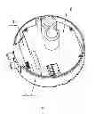
FIG. 1 is a stereogram of a motor controller of the invention;
FIG. 2 is an exploded view of a motor controller of the invention;
FIG. 3 is a assembly stereogram of a control box and a control panel of the invention;
FIG. 4 is a structure diagram of a motor controller of the invention;
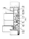
FIG. 5 is a cross-sectional view taken from part A-A of FIG. 4; and
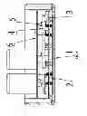
FIG. 6 is a cross-sectional view taken from part B-B of FIG. 4.
DETAILED DESCRIPTION OF THE EMBODIMENTS
For further illustrating the invention, experiments detailing a motor controller are described below combined with the drawings.
Example 1
As shown in FIGS. 1-6, a motor controller comprises: a control box 1, a control panel 2, and a plurality of IGBT modules 3. A plurality of first bosses 11 are disposed on a bottom of the control box 1. The control panel 2 is disposed and fixed on the first bosses 11 by screws. The IGBT modules 3 are disposed on the control panel 2. A heat dissipation boss 12 is disposed on the bottom of the control box 1 outside the control panel 2. The IGBT modules 3 are attached to an end surface of the heat dissipation boss 12 by a locking device.
Example 2
Based on Example 1, the following technical features are added: the locking device comprises: a compression bar 4, and a screw 5. The compression bar 4 presses against two IGBT modules 3 and is fixed on the heat dissipation boss 12 by a screw 5.
Example 3
Based on Example 1 or 2, the following technical features are added: a power panel 6 is disposed inside the control box 1 above the control panel 2. The power panel 6 is disposed on a plurality of second bosses 13 arranged on the bottom of the control box 1, and is fixed on the second bosses 13 by screws. The power panel 6 is in electric connection with the control box 2 via a lead terminal.
Example 4
Based on Example 1 or 2, the following technical features are added: a plurality of heat dissipation ribs 120 are disposed on a bottom of the heat dissipation boss 12.
Example 5
Based on Example 1, the following technical features are added: six IGBT modules 3 are provided, and every two IGBT modules are defined as a group.
Example 6
Based on Example 3, the following technical features are added: a height of the second bosses 13 is larger than a height of the first bosses 11.
While particular embodiments of the invention have been shown and described, it will be obvious to those skilled in the art that changes and modifications may be made without departing from the invention in its broader aspects, and therefore, the aim in the appended claims is to cover all such changes and modifications as fall within the true spirit and scope of the invention.
A plurality of the first bosses 11 are disposed on the bottom of the control box 1. The control panel 2 is disposed and fixed on the first bosses 11 by screws. The IGBT modules 3 are disposed on the control panel 2. The heat dissipation boss 12 is disposed outside the control panel 2 on the bottom of the control box 1. The IGBT modules 3 are attached to the end surface of the heat dissipation boss 12 by the locking device. The invention has a simple structure, low cost, simplified production procedure, simple and easy installation procedure, reasonable layout, and good heat dissipation effect.
Claims
The invention claimed is:1. A motor controller, comprising:
a) a control box (1), the control box (1) comprising a bottom comprising a plurality of first bosses (11);
b) a control panel (2);
c) a plurality of IGBT modules (3); and
d) a heat dissipation boss (12), the heat dissipation boss (12) comprising an end surface;
wherein
the control panel (2) is disposed and fixed on the first bosses (11) by screws;
the IGBT modules (3) are disposed on the control panel (2);
the heat dissipation boss (12) is disposed on the bottom of the control box (1) outside the control panel (2); and
the IGBT modules (3) are attached to and fixed on the end surface of the heat dissipation boss (12) by a locking device.
2. The motor controller of claim 1, wherein
the locking device comprises: a compression bar (4), and a screw (5); and
the compression bar (4) presses against two IGBT modules (3) and is fixed on the heat dissipation boss (12) by a screw (5).
3. The motor controller of claim 1, wherein
a power panel (6) is disposed inside the control box (1) above the control panel (2);
a plurality of second bosses (13) are disposed on the bottom of the control box (1);
the power panel (6) is disposed and fixed on the second bosses (13) by screws; and
the power panel (6) is in electric connection with the control box (2) via a lead terminal.
4. The motor controller of claim 2, wherein
a power panel (6) is disposed inside the control box (1) above the control panel (2);
a plurality of second bosses (13) are disposed on the bottom of the control box (1);
the power panel (6) is disposed and fixed on the second bosses (13) by screws; and
the power panel (6) is in electric connection with the control box (2) via a lead terminal.
5. The motor controller of claim 1, wherein a plurality of heat dissipation ribs (120) are disposed on a bottom of the heat dissipation boss (12).
6. The motor controller of claim 2, wherein a plurality of heat dissipation ribs (120) are disposed on a bottom of the heat dissipation boss (12).
7. The motor controller of claim 1, wherein six IGBT modules (3) are provided and every two IGBT modules are defined as a group.
8. The motor controller of claim 3, wherein a height of the second bosses (13) is larger than a height of the first bosses (11).
9. The motor controller of claim 4, wherein a height of the second bosses (13) is larger than a height of the first bosses (11).
Images & Drawings included:


Sources:
- United States Patent and Trademark Office - verify current appl. status at the USPTO↗
Similar patent applications:
- » 20220166364
Motor control method, motor control model conversion method, motor control system, motor control model conversion system, and motor control model conversion program - » 20210104967
Motor control module, motor control device, motor control system, and motor control method - » 20240171098
MOTOR CONTROL DEVICE, MOTOR CONTROL METHOD, AND A NON-TRANSITORY STORAGE MEDIUM STORING A MOTOR CONTROL PROGRAM FOR A MOTOR CONTROL DEVICE - » 20160239008
Motor control program transferring system, host controller, motor control device, and motor control program transferring method - » 20240388237
MOTOR CONTROLLER, MOTOR CONTROL SYSTEM, AND MOTOR CONTROL METHOD - » 20170237384
Motor controller, motor control method, and non-transitory computer-readable medium encoded with motor control program - » 20160380573
Motor control apparatus, motor control system, motor control method - » 20240272602
MOTOR CONTROL METHOD, MOTOR CONTROL DEVICE, MOTOR CONTROL SYSTEM, AND PROGRAM - » 20200266736
MOTOR CONTROL DEVICE, MOTOR CONTROL METHOD, MOTOR CONTROL PROGRAM, AND ACTUATOR - » 20240243686
MOTOR CONTROL DEVICE, MOTOR CONTROL SYSTEM, MOTOR CONTROL METHOD, AND PROGRAM
Recent applications in this class:
- » 20250293110 2025-09-18
SEMICONDUCTOR MODULE AND POWER CONVERSION UNIT - » 20250259906 2025-08-14
THERMAL PERFORMANCE IN HYBRID BONDED 3D DIE STACKS - » 20250226278 2025-07-10
SEMICONDUCTOR STRUCTURE AND MANUFACTURING METHOD THEREOF - » 20250226277 2025-07-10
SEMICONDUCTOR DEVICE AND MANUFACTURING METHOD THEREOF - » 20250210440 2025-06-26
SEMICONDUCTOR PACKAGE AND MANUFACTURING METHOD FOR THE SAME - » 20250201648 2025-06-19
INTEGRATED CIRCUIT PACKAGES - » 20250201647 2025-06-19
PACKAGE STRUCTURE - » 20250118615 2025-04-10
PACKAGE STRUCTURE INCLUDING A HEAT DISSIPATION STRUCTURE AND METHODS OF FORMING THE SAME - » 20250112105 2025-04-03
SEMICONDUCTOR ASSEMBLIES INCLUDING VERTICALLY INTEGRATED CIRCUITS AND METHODS OF MANUFACTURING THE SAME - » 20250105082 2025-03-27
PACKAGING STRUCTURE AND METHOD FOR FORMING THE SAME
Recent applications for this Assignee:
- » 20170085140 2017-03-23
Plastic-packaged stator and external rotor motor comprising the same - » 20170074273 2017-03-16
Blower comprising a pressure measuring connector - » 20160254712 2016-09-01
Rotor with embedded permanent magnets, assembly structure and motor comprising the same - » 20150372555 2015-12-24
Wire terminal joint of motor stator winding - » 20150372549 2015-12-24
Motor - » 20150229171 2015-08-13
Permanent magnet rotor - » 20150162860 2015-06-11
Method for controlling three-phase brushless DC motor comprising single hall sensor - » 20150162792 2015-06-11
Permanent magnet rotor - » 20150091482 2015-04-02
Variable speed fan motor - » 20140183983 2014-07-03
Plastic-package motor