Device for securing one face wall mesh to vertical rebar and standard concrete forms
US20140041333A1
2014-02-13
13/898,330
2013-05-20
✅ Patent granted
US 9,097,010 B2
2015-08-04
-
-
Chi Q Nguyen
2033-05-20
Abstract:
A simple, one-piece mechanical tie allows quick and secure connection between rebar, mesh and form. A single piece of tie wire can secure the tie to the mesh and rebar, making the installation process much quicker than conventional processes. Unlike other devices that have multiple pieces where, if one piece is lost, the tie is unusable, the current device is designed as a single piece making installation and use quick and simple.
Applicant:
Interested in similar patents?
Get notified when new applications in this technology area are published.
Classification:
E04B2/8647 » CPC main
Walls, e.g. partitions, for buildings; Wall construction with regard to insulation; Connections specially adapted to walls; Walls made by casting, pouring, or tamping made in permanent forms with ties going through the forms
E04B1/4178 » CPC further
Constructions in general; Structures which are not restricted either to walls, e.g. partitions, or floors or ceilings or roofs; Connections for building structures in general; Separate connecting elements; Connecting devices specially adapted for embedding in concrete Masonry wall ties
B21F1/00 » CPC further
Wire working characterised by operations performed
B21F1/00 » CPC further
Bending wire other than coiling; Straightening wire
B21F1/06 » CPC further
Bending wire other than coiling; Straightening wire Bending wire-eyes
E04B2/86 » CPC further
Walls, e.g. partitions, for buildings; Wall construction with regard to insulation; Connections specially adapted to walls; Walls made by casting, pouring, or tamping made in permanent forms
E04C5/167 » CPC further
Reinforcing elements, e.g. for concrete; Auxiliary elements therefor; Auxiliary parts for reinforcements, e.g. connectors, spacers, stirrups; Connectors or means for connecting parts for reinforcements the reinforcements running in different directions Connection by means of clips or other resilient elements
E04C5/20 » CPC further
Reinforcing elements, e.g. for concrete; Auxiliary elements therefor; Auxiliary parts for reinforcements, e.g. connectors, spacers, stirrups of material other than metal or with only additional metal parts, e.g. concrete or plastics spacers with metal binding wires
Y10T24/149 » CPC further
Buckles, buttons, clasps, etc.; Bale and package ties, hose clamps Wire
Y10T403/7176 » CPC further
Joints and connections; Rod side to plate or side Resilient clip
E04B1/38 IPC
Constructions in general; Structures which are not restricted either to walls, e.g. partitions, or floors or ceilings or roofs Connections for building structures in general
E04C5/00 IPC
Reinforcing elements, e.g. for concrete; Auxiliary elements therefor
E04C5/12 » CPC further
Reinforcing elements, e.g. for concrete; Auxiliary elements therefor; Members specially adapted to be used in prestressed constructions Anchoring devices
E04B1/41 IPC
Constructions in general; Structures which are not restricted either to walls, e.g. partitions, or floors or ceilings or roofs; Connections for building structures in general; Separate connecting elements Connecting devices specially adapted for embedding in concrete
E04C5/16 IPC
Reinforcing elements, e.g. for concrete; Auxiliary elements therefor Auxiliary parts for reinforcements, e.g. connectors, spacers, stirrups
Description
CROSS-REFERENCE TO RELATED APPLICATION
This application claims the benefit of priority of U.S. provisional application No. 61/681,134, filed Aug. 8, 2012, the contents of which are herein incorporated by reference.
BACKGROUND OF THE INVENTION
The present invention relates to concrete wall forming devices and methods and more particularly, to device for securing one face wall mesh to vertical rebar and standard concrete forms.
In the construction of concrete walls of fixed width, securing one face wall mesh to rebar and forms is an expensive and cumbersome process. Conventional ties for this purpose are made up of multiple parts that either had to be connected and adjusted for the width of the concrete wall, or secured with a nut and link. If one piece was lost, the tie was unusable.
As can be seen, there is a need for a simple, one-piece tie design that allows the tie to be easily handled and installed by whomever is installing the mesh and form and pouring the concrete.
SUMMARY OF THE INVENTION
In one aspect of the present invention, a device for securing one face wall mesh to vertical rebar and standard concrete forms comprises a tie rod; a bend formed in a first direction at a first end of the tie rod; a U-bend, formed in a second direction, opposite that of the first direction, the U-bend having a curvature operable to retain rebar therewithin; and a shaft tie operable to wrap around an opening formed by the U-bend, proximate to the bend in the tie rod.
In another aspect of the present invention, a device for securing one face wall mesh to vertical rebar and standard concrete forms comprises a tie rod having a first end and a second end; a bend formed in a first direction at the first end of the tie rod; a U-bend, formed in a second direction, opposite that of the first direction, located adjacent the bend, the U-bend having a curvature operable to retain rebar therewithin; a wire tie operable to wrap around an opening formed by the U-bend, proximate to the bend in the tie rod; and one of a knob and a loop disposed on a second end of the tie rod.
In a further aspect of the present invention, a method for securing one face wall mesh to vertical rebar and standard concrete forms comprises bending a tie rod in a first direction at a first end of the tie rod; forming a U-bend in a second direction, opposite that of the first direction; retaining rebar in a curvature formed by the U-bend; and wrapping a shaft tie around an opening formed by the U-bend, proximate to the bend in the tie rod.
These and other features, aspects and advantages of the present invention will become better understood with reference to the following drawings, description and claims.
BRIEF DESCRIPTION OF THE DRAWINGS
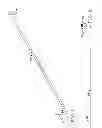
FIG. 1 is a perspective view of a knob style tie according to an exemplary embodiment of the present invention;
FIG. 2 is a side view of the knob style tie of FIG. 1;
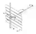
FIG. 3 is a perspective view of the tie of FIG. 1, in use to secure vertical rebar to a concrete form;
FIG. 4 is a cross-sectional view as taken along line 4-4 of FIG. 3;
FIG. 5 is a side view of the rebar / concrete form tie in use as shown in FIG. 3; and
FIG. 6 is a perspective view of a loop style tie according to another exemplary embodiment of the present invention.
DETAILED DESCRIPTION OF THE INVENTION
The following detailed description is of the best currently contemplated modes of carrying out exemplary embodiments of the invention. The description is not to be taken in a limiting sense, but is made merely for the purpose of illustrating the general principles of the invention, since the scope of the invention is best defined by the appended claims.
Broadly, an embodiment of the present invention provides a simple, one-piece mechanical tie that allows quick and secure connection between rebar, mesh and form. A single piece of tie wire can secure the tie to the mesh and rebar, making the installation process much quicker than conventional processes. Unlike other devices that have multiple pieces where, if one piece is lost, the tie is unusable, the device of the present invention is designed as a single piece making installation and use quick and simple.
Referring now to FIGS. 1 through 5, a knob style tie 10 can include a bend 14 at a first end thereof. The bend 14 can include a first bend 14-1 (see FIG. 2), having a curved radius causing the tie to bend back on itself (about 180 degrees), and a second bend 14-2 causing the first end of the tie to bend away from the tie at an angle from about 30 to about 70 degrees. Typically the first bend 14-1 can have a radius designed to receive rebar 16 therein. A knob 24 can be disposed on the end of the knob style tie 10. A connector 26, such as a tie of wire, can be secured from the second bend 14-2 to the tie prior to the first bend 14-1, as shown in FIG. 4.
Referring to FIG. 6, a loop style tie 12 can be designed similar to the knob style tie 10, described above, except that a loop 22 can be disposed at the end thereof in place of the knob 24.
To make the tie of the present invention, a standard snap tie or loop tie can be cut to the appropriate length. The cut end of the tie can then be deformed at the end to act as a catch for the wire used to secure the tie. The tie can then be bent into a 180 degree bend (first bend 14-1), creating an inside radius capable of hooking around an existing installed rebar 16 and extending through the one faced wall mesh 18. With the tie 10, 12 hooked around the rebar 16 and sticking through the mesh 18, a single tie of wire (connector 26) can be secured around the step of the tie and under the deformed end (second bend 14-2) of the tie. Thus secured, the mesh 18 cannot slide off the tie 10, 12 and the tie cannot slide off the rebar 16.
Depending on the forming system in use, the loop end 22 or the snap end 24 of the tie is secured through the strippable side of the wall, making a complete rigid chamber for the pouring of a concrete wall in a fixed diameter.
The system of the present invention can provide the user with a quick and secure connection between the rebar, mesh and form, greatly simplifying the process as compared to conventional methods.
It should be understood, of course, that the foregoing relates to exemplary embodiments of the invention and that modifications may be made without departing from the spirit and scope of the invention as set forth in the following claims.
Claims
What is claimed is:1. A device for securing one face wall mesh to vertical rebar and standard concrete forms, comprising:
a tie rod;
a bend formed in a first direction at a first end of the tie rod;
a U-bend, formed in a second direction, opposite that of the first direction, the U-bend having a curvature operable to retain rebar therewithin; and
a shaft tie operable to wrap around an opening formed by the U-bend, proximate to the bend in the tie rod.
2. The device of claim 1, wherein the bend is from about 30 to about 70 degrees.
3. The device of claim 1, wherein the U-bend is about 180 degrees.
4. The device of claim 1, wherein the shaft tie is a wire tie.
5. The device of claim 1, further comprising a knob on a second end of the tie rod.
6. The device of claim 1, further comprising a loop on a second end of the tie rod.
7. A device for securing one face wall mesh to vertical rebar and standard concrete forms, comprising:
a tie rod having a first end and a second end;
a bend formed in a first direction at the first end of the tie rod;
a U-bend, formed in a second direction, opposite that of the first direction, located adjacent the bend, the U-bend having a curvature operable to retain rebar therewithin;
a wire tie operable to wrap around an opening formed by the U-bend, proximate to the bend in the tie rod; and
one of a knob and a loop disposed on a second end of the tie rod.
8. A method for securing one face wall mesh to vertical rebar and standard concrete forms, comprising:
bending a tie rod in a first direction at a first end of the tie rod;
forming a U-bend in a second direction, opposite that of the first direction;
retaining rebar in a curvature formed by the U-bend; and
wrapping a shaft tie around an opening formed by the U-bend, proximate to the bend in the tie rod.
9. The method of claim 8, wherein the shaft tie is a wire tie.
10. The method of claim 8, wherein one of a knob and a loop is disposed on a second end of the tie rod.
Images & Drawings included:


Sources:
- United States Patent and Trademark Office - verify current appl. status at the USPTO↗
Recent applications in this class:
- » 20240328153 2024-10-03
Insulated Building Panel Structure - » 20240301690 2024-09-12
SYSTEM AND COMPONENTS THEREOF FOR FASTENING STRUCTURAL COMPONENTS IN INSULATED CONCRETE FORMWORK - » 20240295121 2024-09-05
FABRIC-FORMED UNSTABILIZED POURED EARTH AND METHOD THEREOF - » 20230304284 2023-09-28
Structural energy-saving, heat-insulated and decorative integrated plate and manufacturing method therefor - » 20200157808 2020-05-21
Stacking clip for concrete forming panel systems - » 20200157807 2020-05-21
Concrete form with removable sidewall - » 20200123768 2020-04-23
Permanent Concrete Formwork And Method For Manufacturing A Metal-Concrete Composite Structure Using Such A Formwork - » 20160281355 2016-09-29
WALL FORMING SYSTEM AND KIT THEREOF - » 20150052839 2015-02-26
Insulated concrete form wall having a bracket attaching a rim joist thereto - » 20140059961 2014-03-06
Prefabricated thermal insulating composite panel, assembly thereof, moulded panel and concrete slab comprising same, method and mould profile for prefabricating same