Electronic device having self diagnosis function and self diagnosis method using the same
US20140068332A1
2014-03-06
14/018,615
2013-09-05
✅ Patent granted
US 10,037,256 B2
2018-07-31
-
-
Michael Nghiem | Peter Ngo
Sughrue Mion, PLLC
2035-08-08
Abstract:
An electronic device which has a self diagnosis function and a self diagnosis method using the same are provided. The electronic device includes: an interface which receives a user's selection signal for a hardware of an object to be diagnosed; and a controller which provides a plurality of lines connected to the hardware of the object to be diagnosed with a signal for diagnosis according to the selection signal which is received through the interface and calculates a diagnosis result for the hardware of diagnosis object according to a comparison result of the signal for diagnosis with a return signal which is returned from the hardware of the object to be diagnosed by a loop-back.
Inventors:
- Hyun-ho KIM 74 🇰🇷 Seoul, South Korea
- Ji-won KIM 74 🇰🇷 Seoul, South Korea
- Sang-eun LEE 19 🇰🇷 Seoul, South Korea
- Young-hun CHOI 12 🇰🇷 Hwaseong-si, South Korea
- Ju-hyun CHOE 3 🇰🇷 Hwaseong-si, South Korea
- Eun-young KIM 35 🇰🇷 Seoul, South Korea
- Hyun-ho Kim 1 🇺🇸 Seoul, KS, United States
Assignee:
- SAMSUNG ELECTRONICS CO., LTD. 90,318 🇰🇷 Suwon-si, South Korea
Applicant:
Interested in similar patents?
Get notified when new applications in this technology area are published.
Classification:
G06F11/27 » CPC main
Error detection; Error correction; Monitoring; Detection or location of defective computer hardware by testing during standby operation or during idle time, e.g. start-up testing; Functional testing Built-in tests
G05B23/0256 » CPC further
Testing or monitoring of control systems or parts thereof; Electric testing or monitoring by means of a monitoring system capable of detecting and responding to faults characterised by the fault detection method dealing with either existing or incipient faults injecting test signals and analyzing monitored process response, e.g. injecting the test signal while interrupting the normal operation of the monitored system; superimposing the test signal onto a control signal during normal operation of the monitored system
G06F11/221 » CPC further
Error detection; Error correction; Monitoring; Detection or location of defective computer hardware by testing during standby operation or during idle time, e.g. start-up testing using arrangements specific to the hardware being tested to test buses, lines or interfaces, e.g. stuck-at or open line faults
G09G5/006 » CPC further
Control arrangements or circuits for visual indicators common to cathode-ray tube indicators and other visual indicators; Details of a display terminal, the details relating to the control arrangement of the display terminal and to the interfaces thereto Details of the interface to the display terminal
G09G2320/0693 » CPC further
Control of display operating conditions; Adjustment of display parameters Calibration of display systems
G09G2330/12 » CPC further
Aspects of power supply; Aspects of display protection and defect management Test circuits or failure detection circuits included in a display system, as permanent part thereof
G05B23/02 IPC
Testing or monitoring of control systems or parts thereof Electric testing or monitoring
G06F11/22 IPC
Error detection; Error correction; Monitoring Detection or location of defective computer hardware by testing during standby operation or during idle time, e.g. start-up testing
G09G3/00 IPC
Control arrangements or circuits, of interest only in connection with visual indicators other than cathode-ray tubes
G09G5/00 IPC
Control arrangements or circuits for visual indicators common to cathode-ray tube indicators and other visual indicators
G06F11/24 » CPC main
Error detection; Error correction; Monitoring; Detection or location of defective computer hardware by testing during standby operation or during idle time, e.g. start-up testing Marginal checking or other specified testing methods not covered by , e.g. race tests
G09G3/006 » CPC further
Control arrangements or circuits, of interest only in connection with visual indicators other than cathode-ray tubes Electronic inspection or testing of displays and display drivers, e.g. of LED or LCD displays
Description
CROSS-REFERENCE TO RELATED APPLICATION
This application claims priority from Korean Patent Application No. 10-2012-0098397, filed on Sep. 5, 2012 in the Korean Intellectual Property Office, the disclosure of which is incorporated herein by reference.
BACKGROUND
1. Field
Apparatuses and methods consistent with the exemplary embodiments relate to an electronic device, and more particularly to an electronic device having a self diagnosis function and a self diagnosis method using the same.
2. Description of the Related Art
An inspection of the performance of a component of an electronic device, or an inspection of a signal line for the sending/receiving of signals to/from the electronic device is carried out by watching a screen which is connected to an external device during a manufacturing process.
For example, an inspection of the port of a High Definition Multimedia Interface (HDMI) is carried out by several external devices or distributors and a HDMI cable.
Thus, it takes a long time to inspect each port because the inspection is carried out in consecutive order, and a consumer is unable to inspect the port by himself. Accordingly, there is a need for a system which allows an electronic device to perform a self-diagnosis operation easily.
SUMMARY
Accordingly, one or more exemplary embodiments may provide an electronic device having a self diagnosis function and a self diagnosis method using the same which carries out a self diagnosis operation without inserting an external device into the electronic device or without an external input device.
One or more exemplary embodiments may provide an electronic device having a self diagnosis function and a self diagnosis method using the same which shortens an inspection time for manufacturing of an electronic device.
One or more exemplary embodiments may provide an electronic device having a self diagnosis function and a self diagnosis method using the same which helps a consumer to conveniently inspect an electronic device by himself.
One or more exemplary embodiments may provide an electronic device having a self diagnosis function and a self diagnosis method using the same which carry out a self diagnosis method using a loop-back operation.
The foregoing and/or other aspects may be achieved by providing an electronic device including an interface configured to receive a user's selection signal for a hardware of an object to be diagnosed; and a controller configured to provide a plurality of lines connected to the hardware of the object to be diagnosed with a signal for diagnosis according to a selection signal which is received through the interface, and calculate a diagnosis result for the hardware of the object to be diagnosed according to a comparison result of the signal for diagnosis with a return signal which is returned from the hardware of the object to be diagnosed by a loop-back operation.
According to an aspect of another exemplary embodiment, the signal for diagnosis may have a DC voltage or a frequency which is provided to the lines.
According to an aspect of another exemplary embodiment, the signal for diagnosis may have different values for each line of the plurality of lines.
According to an aspect of another exemplary embodiment, the diagnosis about the lines may be not in consecutive order but in simultaneous order.
According to an aspect of another exemplary embodiment, the controller may show the diagnosis result on an On Screen Display (OSD).
According to an aspect of another exemplary embodiment, the hardware of the object to be diagnosed may be a connector having a port which is connected to an external device and the connector may form a loop-back by a cap applying an electric current.
According to an aspect of another exemplary embodiment, the connector may be a connector of a Universal Serial Bus (USB) interface or an HDMI.
According to an aspect of another exemplary embodiment, the electronic device may further include a memory which has information of a diagnosis period for the hardware of the object to be diagnosed.
According to an aspect of another exemplary embodiment, the diagnosis period may be determined by a user or set in advance.
The foregoing and/or other aspects may be achieved by providing a self diagnosis method for an electronic device, the method including displaying an instruction screen for the self diagnosis operation; receiving a selection signal for a hardware of the object to be diagnosed from a user; providing a plurality of lines connected to the hardware of the object to be diagnosed with a signal for diagnosis; receiving a return signal from the hardware of the object to be diagnosed by a loop-back operation; comparing the return signal with the signal for diagnosis; calculating a diagnosis result for the hardware of the object to be diagnosed according to the comparison result; and displaying the diagnosis result.
BRIEF DESCRIPTION OF THE DRAWINGS
The above and/or other aspects will become apparent and more readily appreciated from the following description of exemplary embodiments, taken in conjunction with the accompanying drawings, in which:
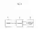
FIG. 1 illustrates an electronic device having a self diagnosis function according to an exemplary embodiment.
FIG. 2 illustrates the configuration for a self diagnosis execution for a HDMI according to an exemplary embodiment.
FIG. 3 illustrates the configuration for a self diagnosis execution for a USB interface according to other exemplary embodiment.
FIG. 4 illustrates the configuration for a self diagnosis execution for a video circuit according to another exemplary embodiment.
FIG. 5 illustrates a flow chart of a self diagnosis method of an electronic device.
FIG. 6 illustrates the instruction screen for self diagnosis.
FIG. 7 illustrates the result screen for the self diagnosis.
FIG. 8 illustrates the configuration screen for setting the period of self diagnosis.
DETAILED DESCRIPTION OF EXEMPLARY EMBODIMENTS
Below, “an electronic device” means an electronic product which has a plurality of components. Exemplary embodiments will be described in detail with reference to accompanying drawings so as to be easily realized by a person having ordinary skill in the art. The exemplary embodiments may be embodied in various forms without being limited to the exemplary embodiments set forth herein. Descriptions of well-known parts are omitted for clarity, and like reference numerals refer to like elements throughout.
FIG. 1 illustrates an electronic device having a self diagnosis function according to an exemplary embodiment. FIG. 1 shows an interface 100 which receives the signal of a user's selection about the hardware of the object to be diagnosed, and a controller 200 which provides a plurality of lines connected to the hardware of the object to be diagnosed with the signal for diagnosis according to a selection signal which is received through the interface 100, and calculates a diagnosis result according to a comparison result obtained by comparing the signal for diagnosis with a return signal which is returned from the hardware of the object to be diagnosed 300 by a loop-back operation. The diagnosis result for the hardware of the object to be diagnosed may be represented as whether at least a line connected to the hardware of the object to be diagnosed is cut off or disconnected, or whether different or adjacent channels have short-circuited each other.
Even though not illustrated in FIG. 1, a display may be added to the electronic device according to an exemplary embodiment in order to receive a control signal from the controller 200 and display the diagnosis result. The diagnosis result may be displayed in a manner that is recognizable by a user. For example, the diagnosis result may be displayed as a text which has a 7-segment shape or variable forms through the display. The diagnosis result may also be expressed as a sound output including an error sound, etc. Therefore a display is a preferable but not a necessary component.
FIG. 2 illustrates an electronic device for a self diagnosis operation using HDMI according to an exemplary embodiment. As shown in FIG. 2, a controller 210 may include a diagnosis signal generator 211 and a reception and judgment unit 212. Since the controller 210 is a semiconductor chip, the diagnosis signal generator 211 and the reception and judgment unit 212 may not be hardware components but may be implemented as logic algorithm. The signal transmitted from the diagnosis signal generator 211 is transmitted to a HDMI 310, formed as a loop-back by a cap 410 applying an electric current. The controller 210 inspects the hardware of the object to be diagnosed by forming several or a plurality of loops for inspection of a short-circuit or a disconnection between adjacent components. In addition, the controller 210 may permit different signals according to adjacent components for inspection of a short-circuit or a disconnection between adjacent components. The reception and judgment unit 212 receives a return signal and compares the received return signal to a signal generated from the diagnosis signal generator 211, and judges an abnormality of the HDMI 310 according to a comparison result. The controller 210 is able to inspect whole ports by the loop-back operation not in consecutive order, but simultaneously.
FIG. 3 illustrates an electronic device for a self diagnosis using a USB interface according to another exemplary embodiment. According to the exemplary embodiment illustrated in FIG. 3, a first port 225 (Port1) among a plurality of ports (Port1, Port2, Port3, and Port4,) is inspected. The ports are formed at a USB hub 200, which executes a control function. A signal generated from a diagnosis signal generator 222 is transmitted to the port 225 after passing by a routing logic and port controller 224. This signal may be 1 byte, and is saved in a memory 221. This signal is outputted through a D+ terminal of the port 225, and is inputted to a D− terminal of the port 225 through a cap 320 applying an electric current. The cap 320 applying an electric current may form a loop-back circuit. A digital logic unit 223 judges an abnormality of the port 225 by comparing a signal which is received through the D− terminal and passed by the routing logic and port controller 224, to a signal saved in the memory 221.
FIG. 4 illustrates an electronic device for a self diagnosis of a video circuit according to another exemplary embodiment. As shown in FIG. 4, an impedance matching is used through a 100Ω resistor generally between a video main board 230 executing a control function and a video output board 330. A controller 210 may execute a self diagnosis using a resistor for an impedance matching, without using an external device, by applying an internal DC power supply. Namely, the main board 230 of the controller 210 outputs a DC power supply through an Even1+ terminal of the main board 230 and determines a short-circuit or a disconnection by discriminating a voltage at an Even1− terminal of the main board 230 returned by a loop-back through a 100Ω resistor) for an impedance matching of the video output board 330.
On the other hand, the controller 210 may discriminate each line and a short-circuit between different or adjacent channels by outputting different voltages to an Even2+ terminal and an Even3+ terminal. Then, different frequencies may be used according to each channel. In other words, the controller 210 may check a disconnection of each of the lines and a short-circuit between adjacent channels by transmitting different DC voltages or different frequencies to each of the lines.
FIG. 5 shows a flow chart of a self diagnosis method of an electronic device. At first, when a manipulation for executing a self diagnosis function is inputted by a user, the input is transmitted to a controller 200 through an interface 100. For example, a user who uses a display apparatus such as a television (TV) or a monitor, may select a function for self diagnosis using a menu button provided in the display apparatus or a remote controller (operation S301).
The controller 200 may display a guide screen for a self diagnosis operation on a display apparatus, for example, with on screen display (OSD) as shown in FIG. 6. Namely, the controller 200 may display a list of hardware which performs a self diagnosis function. For example, a connector connects an external apparatus to the display apparatus. The connector may be displayed on the display apparatus as a component terminal for a signal from an external component, an audio/video input and output terminal, a high definition multimedia interface (HDMI) terminal, a universal serial bus (USB) terminal to exchange an own signal for a signal of an external apparatus, an Ethernet terminal for connecting the Internet (operation S302).
When a user selects a hardware of the object to be diagnosed through a guide screen in OSD, the controller 200 receives the selection signal about the hardware of the object to be diagnosed. The selection of a user may be executed by various methods. For example, the selection of a user may be executed by a remote controller or a touch panel in the case where a display apparatus has a touch screen. If the electronic device for a self diagnosis according to an exemplary embodiment is a computer, the selection of a user may be executed by a mouse or a keyboard (operation S303).
A signal of the user's selection is transmitted to the controller 200 through the interface 100. The controller 200 provides a plurality of lines connected to the hardware of the object to be diagnosed with a signal for diagnosis. The signal for diagnosis may be a signal with a DC voltage or frequency, and may be transmitted with each different values to the plurality of lines simultaneously (operation S304).
In the next operation, the controller 200 receives a return signal from the hardware of the object to be diagnosed by a loop-back operation (operation S305), and compares the received return signal to the provided signal for diagnosis (operation S306).
According to a comparison result, the controller 200 calculates the diagnosis result about the hardware of the object to be diagnosed (operation S307), and outputs the diagnosis result as shown in FIG. 7. Therefore, if a connector has a problem, a user may be provided with a guide explaining how the connector should be repaired (operation S308).
As shown in FIG. 8, a user may set a period for the diagnosis. For example, a user may set the period for the diagnosis to diagnose the hardware of the object to be diagnosed automatically one time per a month when main power is applied thereto. The period of the diagnosis is set according to the number of usage as the case may be. Then, information of the diagnosis period may be saved in the memory.
Although a few exemplary embodiments have been shown and described, it will be appreciated by those skilled in the art that changes may be made in these exemplary embodiments without departing from the principles and spirit of the exemplary embodiments, the scope of which is defined in the appended claims and their equivalents.
Claims
What is claimed is:1. An electronic device having a self diagnosis function, the electronic device comprising:
an interface configured to receive a user's selection signal for a hardware of an object to be diagnosed; and
a controller configured to provide a plurality of lines connected to the hardware of the object to be diagnosed with a signal for diagnosis according to the selection signal, and calculate a diagnosis result for the hardware of the object to be diagnosed according to a result of comparison the signal for diagnosis with a return signal which is returned from the hardware of the object to be diagnosed by a loop-back operation.
2. The electronic device according to claim 1, wherein the signal for diagnosis has a DC voltage which is provided to the plurality of lines.
3. The electronic device according to claim 1, wherein the signal for diagnosis has a frequency which is provided to the plurality of lines.
4. The electronic device according to claim 2, wherein the signal for diagnosis has different values for each line of the plurality of lines.
5. The electronic device according to claim 1, wherein the controller shows a list of the hardware of the object to be diagnosed on an On Screen Display (OSD).
6. The electronic device according to claim 1, wherein the controller provides the lines with the signal for diagnosis simultaneously.
7. The electronic device according to claim 1, further comprising a memory configured to store information of a diagnosis period for the hardware of the object to be diagnosed.
8. The electronic device according to claim 7, wherein the diagnosis period is determined by a user.
9. The electronic device according to claim 7, wherein the diagnosis period is set in advance.
10. The electronic device according to claim 1, wherein the hardware of the object to be diagnosed is a connector which has a port connected to an external device and forms the loop-back by a cap applying an electric current.
11. The electronic device according to claim 10, wherein the connector is a universal serial bus (USB) interface.
12. The electronic device according to claim 10, wherein the connector is a high definition multimedia interface (HDMI).
13. A self diagnosis method for an electronic device, the method comprising:
displaying an instruction for the self diagnosis on a screen;
receiving a selecting signal for a hardware of an object to be diagnosed from a user;
providing at least one of a plurality of lines connected to the hardware of the object to be diagnosed with a signal for diagnosis;
receiving a return signal from the hardware of the object to be diagnosed by a loop-back operation;
comparing the return signal with the signal for diagnosis;
calculating a diagnosis result for the hardware of the object to be diagnosed according to a result of the comparing; and
displaying the diagnosis result.
14. The method according to claim 13, wherein the at least one of the plurality of lines receives a DC voltage.
15. The method according to claim 13, wherein the at least one of the plurality of lines receives a signal having different frequencies.
16. The method according to claim 13, wherein the diagnosis result is displayed on an on screen display (OSD).
17. The method according to claim 13, further comprising saving the signal for diagnosis.
18. A method for performing self-diagnosis on an electronic device, the method comprising:
selecting a hardware of an object to be diagnosed;
transmitting a signal for diagnosis to the hardware of the object to be diagnosed;
receiving a return signal from the hardware of the object to be diagnosed;
comparing the signal for diagnosis with the return signal, and
calculating a diagnosis result based on a result of the comparing.
19. The method of claim 18, wherein the hardware is a connector having a port which is connected to an external device.
20. The method of claim 19, wherein the connector is at least one of a component terminal; an audio/video terminal; a high definition multimedia interface (HDMI); a Universal Serial Bus (USB), and an Ethernet terminal.
21. The method of claim 18, wherein the signal for diagnosis is at least one of a DC voltage or a frequency.
22. The method of claim 18, wherein the return signal is received based on a loop-back operation.
Images & Drawings included:


Sources:
- United States Patent and Trademark Office - verify current appl. status at the USPTO↗
Recent applications in this class:
- » 20250265162 2025-08-21
Instances For Built-In Self Testing - » 20250258746 2025-08-14
EVALUATION OF MEMORY DEVICE HEALTH MONITORING LOGIC - » 20250217252 2025-07-03
TIME-TRIGGERED COMPUTER SYSTEM WITH A HIGH LEVEL OF DIAGNOSTIC COVERAGE - » 20250181467 2025-06-05
EVALUATION DEVICE AND EVALUATION METHOD - » 20250173233 2025-05-29
ASSESSING DISPLAY HEALTH IN RESPONSE TO ACCIDENTS - » 20250123935 2025-04-17
CHIP WITH BUILT-IN VERIFICATION AND METHOD FOR BUILT-IN CHIP VERIFICATION - » 20250086081 2025-03-13
FUNCTIONAL TESTING DEVICE AND SYSTEM - » 20250086080 2025-03-13
FUNCTIONAL TESTING METHOD - » 20250013547 2025-01-09
INFORMATION PROCESSING SYSTEM, INFORMATION PROCESSING METHOD, AND NON-TRANSITORY COMPUTER READABLE MEDIUM - » 20250004896 2025-01-02
METHOD AND APPARATUS TO PROACTIVELY SCREEN HARDWARE ERRORS OF A COMPUTER PROCESSING SYSTEM
Recent applications for this Assignee:
- » 20250294923 2025-09-18
BACKLIGHT UNIT INCLUDING A PLURALITY OF LEDS AND ASSOCIATED DISTRIBUTED BRAGG REFLECTORS - » 20250294902 2025-09-18
IMAGE SENSOR - » 20250294901 2025-09-18
IMAGE SENSOR AND METHOD FOR FABRICATING THE SAME - » 20250294900 2025-09-18
SEMICONDUCTOR DEVICE, IMAGE SENSOR, AND LAYOUT DESIGN METHOD - » 20250294816 2025-09-18
SEMICONDUCTOR DEVICES AND METHODS OF FABRICATING THE SAME - » 20250294784 2025-09-18
CAPACITOR, MEMORY DEVICE INCLUDING THE CAPACITOR, AND METHOD OF MANUFACTURING THE CAPACITOR - » 20250294730 2025-09-18
SEMICONDUCTOR DEVICE - » 20250294726 2025-09-18
SEMICONDUCTOR DEVICE - » 20250294721 2025-09-18
SEMICONDUCTOR DEVICE - » 20250294720 2025-09-18
SEMICONDUCTOR DEVICES