PUMPING-TYPE COSMETIC CONTAINER
US20140103071A1
2014-04-17
14/124,355
2012-06-14
Abstract:
A pumping-type cosmetic container is characterized by an elastic discharging portion being formed on the top of a pumping member and opened by the pressure of contents of the container, and a sealing shaft being coupled to the elastic discharging portion such that sealing is enabled without the use of a separate check valve and air is prevented from entering into a bellows.
Inventors:
- You-Seob Kim 20 🇰🇷 Incheon, South Korea
- Sung-Sin Kim 11 🇰🇷 Incheon, South Korea
- Sung Hwan KIM 29 🇰🇷 Incheon, South Korea
- Min-Woo Park 2 🇰🇷 Incheon, South Korea
- Hak-Chan Kim 14 🇰🇷 Incheon, South Korea
- Yu-Han Ko 1 🇰🇷 Incheon, South Korea
- Seong-Ho Kim 3 🇰🇷 Incheon, South Korea
Interested in similar patents?
Get notified when new applications in this technology area are published.
Classification:
A45D34/00 » CPC main
Containers or accessories specially adapted for handling liquid toilet or cosmetic substances, e.g. perfumes
B65D37/00 IPC
Portable flexible containers not otherwise provided for
Description
BACKGROUND
The present invention relates to a pumping-type cosmetic container, and in particular to a pumping-type cosmetic container which makes it possible to prevent air from entering into the interior of a wrinkled tube because sealing effects can be obtained without using a check valve in such a way that an elastic discharge part opened and closed by the pressure of contents is provided at the top of a pumping member, and a sealing shaft is engaged to the elastic discharge part.
A typical pumping-type cosmetic container configured to discharge contents with the aid of a pumping member comprises a container body which stores contents, a pumping member which is engaged to the top of the container body and performs a pumping operation, and a button member which is positioned at the top of the pumping member and enables a pumping operation as a user pressurizes, and a button member which has a discharge hole through which to discharge contents.
The above mentioned typical pumping-type cosmetic container has features in that when a user pressurizes the button member, the pumping member positioned below becomes activated for thereby discharging contents stored in the container body through a discharge hole; however the pumping member has complicated constructions, and the manufacture costs a lot, and it is time-consuming.
Since the pumping member activates a pumping operation with the aid of a metallic spring, the metallic spring may corrode, which spoils the contents.
In order to improve the above mentioned problems, there is developed “a pumping device for a cosmetic container” whose Korean registered patent number is 10-0545007.
In the above mentioned Korean registered patent, the pumping device for discharging part of the fluid stored in the interior of the container comprises a pumping head 10 which is provided at the top of a head housing 20 while sealing it and ascends and descends along the inner surface of a head accommodation rib 22 for thereby depressurizing and pressurizing the fluid in the interior, the bottom of the pumping head 10 being open, and is equipped with a nozzle 11 through which to discharge the fluid of the interior to the outside and a discharge tube 12 which stands downward in the inner center for the purpose of supplying the fluid to the nozzle; a head housing 20 which covers the top of the container while sealing the same and air-tightly seal the open bottom of the pumping head 10 and is equipped with a bottom valve hole 21 at the center of which a bottom valve 60 is disposed, a head accommodation rib 22 being upright so as to air-tightly guide the bottom of the pumping head 10 which ascends and descends along an upper outer surface, a wrinkled tube accommodation rib 23 air-tightly sealing the bottom of the wrinkled tube 30 at the center of the upper surface being upwardly protruding from the outer side of the bottom valve hole 21, an engaging member 24 at an outer lower side being air-tightly engaged to the top of the container 70; an elastic wrinkled tube 30 which is contracted when the pumping head 10 descends and ascends the pumping head 10 by means of an elastic force when a descending pressure is removed, the top of which being air-tightly engaged to the bottom of the discharge tube 12 of the pumping head 10, the bottom of which being engaged air-tightly sealing the head housing including the bottom valve hole 21 of the head housing 30; a top valve housing 40 which air-tightly seal the end of the lower side of the discharge tube 12 of the pumping head 10, a top valve hole 41 passing through its center and to which the top valve 50 is engaged; a top valve 50 which is configured to open and close the top valve hole 41 of the top valve housing 40 and opens when the pressure of the interior of the wrinkled tube is higher than the pressure of the interior of the discharge tube 12 of the pumping head 10 and closes when the pressure of the interior of the discharge tube 12 is higher than the pressure of the interior of the wrinkled tube 30; and a bottom valve 60 which is configured to open and close the bottom valve hole 21 of the bottom valve housing 20 and opens when the pressure of the interior of the container 70 is higher than the pressure of the interior of the wrinkled tube 30 and closes when the pressure of the interior of the wrinkled tube 30 is higher than the pressure of the interior of the container 70.
According to the above described registered patent, the pumping operation is obtained using the winkled tube 30 made from a rubber material instead of a metallic spring used in the conventional art. Since the metallic spring is not used, it is possible to prevent the contents from being spoiled when occurs thanks to the corrosion of the metallic spring.
According to the above described registered patent, the top valve housing 40 equipped with the top valve hole 1 discharging the contents is engaged to the pumping head 10, so the top valve 50 opening and closing the top valve hole 41 should be provided. In addition, since the pumping structure is formed of the wrinkled tube 30 and the top valve housing 40, it needs to assemble all the above mentioned elements, which makes the assembling line took complicated, and since more parts are required, the manufacture costs a lot.
Since the weight 53 is required so as to pressurize the top valve 50 in the downward direction for the purpose of sealing the inner side of the wrinkled tube 30, the structure of the top valve 50 becomes complicated. Since the valve body 51 comes into contact with the upper surface of the top valve housing 40, deformation occurs at the end of the valve body 51, which causes a gap to form between an upper surface of the top valve housing 40 and the bottom of the valve body 51, so air may enter into the interior of the wrinkled tube 30, which consequently spoils the contents.
In addition, the granular contents may be solidified between the gaps formed in the check valve owing to the structure of the bottom valve 60, so erroneous operations may occur in the bottom valve 60.
SUMMARY OF THE INVENTION
Accordingly, the present invention is made so as to improve the above mentioned problems. It is an object of the present invention to provide a pumping type cosmetic container which makes it possible to prevent air from entering into the interior of a wrinkled tube because sealing is enabled without using a separate check valve in such a way that an elastic discharge part opened and closed by a pressure of contents is provided at the top of a pumping member, and a sealing shaft is engaged to the elastic discharge part.
It is another object of the present invention to provide a pumping type cosmetic container which can be prevent erroneous operations which used to happen due to the solidified granular contents between the gaps formed in the conventional check valve in such a way the valve member is opened and closed while ascending and descending by changing the structure of the valve member which opens and closes the discharge hole formed at the support part.
To achieve the above objects, there is provided a pumping type cosmetic container according to a first embodiment of the present invention, comprising a container body 100 which stores contents; a support part 200 which is engaged to the top of the container body 100, a content discharge hole 211 being formed at its center, a fixing groove 220 covering the content discharge hole 211; a valve member 300 which is installed at the content discharge hole 211 and opens and closes the content discharge hole 211; a pumping member 400 which is engaged to the support part 200 and is made from an elastic material for thereby discharging out contents through pumping operations and comprises an engaging part 410 which is engaged to the fixing groove 220; a wrinkled tube 420 which extends from the engaging part 410 and is contracted and recovered; a button support part 430 which is formed at an end portion of the wrinkled tube 420; and an elastic discharge part 440 which extends toward an inner side of the button support part 430 and widens with the pressure of the contents and discharges contents; a sealing shaft 500 which is engaged to the top of the pumping member 400 and closes the elastic discharge part 440; and a button member which is engaged covering the pumping member 400 and has a content discharge hole 610 for discharging contents through the pumping operations of the pumping member 400.
To achieve the above objects, there is provided a pumping type cosmetic container according to a second embodiment of the present invention, comprising a container body 100′ which stores contents; a support part 200′ which is engaged to the top of the container body 100′, a content discharge hole 211′ being formed at its center, a protrusion 220′ protruding upward covering the content discharge hole 211′; a pump engaging part 300′ which is installed at the content discharge hole 211′ and is formed of a valve member 310′ for opening and closing the content discharge hole 211′ and a fixing groove 320′ covering the valve member 310′; a pumping member 400′ which is engaged to the pump engaging part 300′ and is made from an elastic material for thereby discharging contents through pumping operations and comprises an engaging part 410′ which is engaged to the fixing groove 320′; a wrinkled tube 420′ which extends from the engaging part 410′ and contracts and recovers; a button support part 430′ which is formed at an end portion of the wrinkled tube 420′; and an elastic discharge part 440′ which extends toward the inner side of the button support part 430′ and widens with the pressure of the contents for thereby discharging out contents; a sealing shaft 500′ which is engaged to the top of the pumping member 400′ and closes the elastic discharge part 440′; and a button member 600′ which is engaged covering the pumping member 400′ and has a content discharge hole 610′ for thereby discharging contents through the pumping operations of the pumping member 400′.
The valve member 300 comprises a mounting part 310 which is formed in a semispherical shape and is mounted at the top of the content discharge hole 211, and an insertion rod 320 which passes through the center of the mounting part 310 and is inserted into the content discharge hole 211, the valve member 300 ascending and descending through the pumping operations of the pumping member 400 for thereby opening and closing the content discharge hole 211.
The sealing shafts 500 and 500′ comprise bodies 510 and 510′ which are engaged covering the tops of the pumping members 400 and 400′ and have content discharge holes 511 and 511′, and closing rods 520 and 520′ which protrude from the centers of the inner upper sides of the bodies 510 and 510′ in downward directions and are engaged to the elastic discharge parts 440 and 440′.
The pump engaging part 300′, the pumping member 400′ and the sealing shaft 500′ are integrate-assembled in a module type.
A fixing protrusion 221′ is formed at an inner upper side of the protrusion 220′, and a support protrusion 411′ is formed at an outer surface of the engaging part 410′ and is supported by the fixing protrusion 221′.
To achieve the above objects, there is provided a pumping type cosmetic container according to a third embodiment of the present invention, comprising a container body 100″ which stores contents; a support part 200″ which is engaged to the top of the container body 100″, a discharge hole 211″ being formed at its center; a first pump engaging part 300″ which is mounted at the support part 200″ and supports the pumping member 400″ and has a first valve member 310″ which opens and closes the content discharge hole 211″; a pumping member 400″ which is engaged to the first pump engaging part 300″ and discharges the contents through the pumping operations and is made from an elastic material in a bellows type; a second pump engaging part 500″ which is engaged to the top of the pumping member 400″ and has a content discharge hole 512″ at its center and a second valve member 520″ which opens and closes depending the discharge of the content discharge hole 512″; and a button member 600″ which is engaged covering the top of the pumping member 400″ and has a content discharge hole 610″ which communicates with the content discharge hole 512″ for the contents to be discharged through the pumping operations of the pumping member 400″.
A first fixing groove 320″ is formed at the first pump engaging part 300″ while covering the first valve member 310″ so as to support the pumping member 400″.
The pumping member 400″ comprises a first engaging part 410″ which is engaged to the first fixing groove 320″; a wrinkled tube 420″ which extends from the first engaging part 410″ and contracts and recovers; and a second engaging part 430″ which is engaged to an end portion of the wrinkled tube 420″ and has a content moving hole 431″ at its center and extends upward covering the content moving hole 431″.
A protrusion part 220″ protrudes upward from the center of the inner side of the support part 200″ and covers the content discharge hole 211″ for the first pump engaging part 300″ and the first engaging part 410″ to be engaged.
The first pump engaging part 300″, the pumping member 400″ and the second pump engaging part 500″ are integrate-assembled in a module type.
The pumping type cosmetic container according to the present invention makes it possible to prevent air from entering into the interior of a wrinkled tube because sealing is enabled without using a separate check valve in such a way that an elastic discharge part opened and closed by a pressure of contents is provided at the top of a pumping member, and a sealing shaft is engaged to the elastic discharge part.
In addition, the pumping type cosmetic container according to the present invention can prevent erroneous operations which used to happen due to the solidified granular contents between the gaps formed in the conventional check valve in such a way the valve member is opened and closed while ascending and descending by changing the structure of the valve member which opens and closes the discharge hole formed at the support part.
BRIEF DESCRIPTION OF DRAWINGS
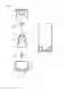
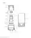
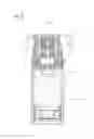
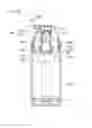
FIG. 1 is a disassembled cross sectional view illustrating a construction of a pumping type cosmetic container according to a first embodiment of the present invention.
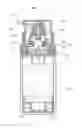
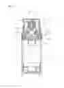
FIG. 2 is an engaged cross sectional view illustrating a construction of a pumping type cosmetic container according to a first embodiment of the present invention.
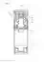
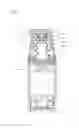
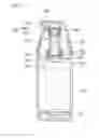
FIGS. 3 and 4 are views for describing a discharge procedure of a content of a pumping type cosmetic container according to a first embodiment of the present invention.
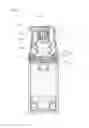
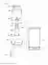
FIG. 5 is a disassembled cross sectional view illustrating a construction of a pumping type cosmetic container according to a second embodiment of the present invention.
FIG. 6 is an engaged cross sectional view illustrating a construction of a pumping type cosmetic container according to a second embodiment of the present invention.
FIGS. 7 and 8 are views for describing a discharge procedure of a content of a pumping type cosmetic container according to a second embodiment of the present invention.
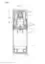
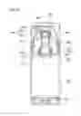
FIG. 9 is a disassembled perspective view illustrating a construction of a pumping type cosmetic container according to a third embodiment of the present invention.
FIG. 10 is an engaged cross sectional view illustrating a construction of a pumping type cosmetic container according to a third embodiment of the present invention.
FIGS. 11 and 12 are views for describing a discharge procedure of a content of a pumping type cosmetic container according to a third embodiment of the present invention.
DETAILED DESCRIPTION OF THE INVENTION
The preferred embodiments of the present invention will be described with reference to the accompanying drawings. It is noted that throughout the specification, the same reference numerals mean same elements.
FIG. 1 is a disassembled cross sectional view illustrating a construction of a pumping type cosmetic container according to a first embodiment of the present invention. FIG. 2 is an engaged cross sectional view illustrating a construction of a pumping type cosmetic container according to a first embodiment of the present invention. FIGS. 3 and 4 are views for describing a discharge procedure of a content of a pumping type cosmetic container according to a first embodiment of the present invention.
As shown in FIGS. 1 to 4, the pumping type cosmetic container according to a first embodiment of the present invention comprises a container body 100, a support part 200, a valve member 300, a pumping member 400, a sealing shaft 500 and a button member 600.
The container body 100 stores contents and is equipped with a piston 110 which is provided at the inner bottom side and ascends and descends as the user uses the contents and a support part 200 for closing the opened top of the container body 100.
The support part 200 is engaged to the top of the container body 100 and supports the pumping member 400 which will be described later, a content input tube 210 being formed at it center so as to form a passage into which the contents are inputted from the container body 100. At the content input tube 210 is formed a content discharge hole 211 for the contents stored in the container body 100 to be discharged.
In the present invention, at the support part 200 is formed a fixing groove 220 which covers the content discharge hole 21 and fixes the engaging part 410 of the pumping member 400. Here, the fixing groove 220 supports the bottom of the engaging part 410 and helps perform the pumping operations of the pumping member 400 when the button member 600 is pressed.
It is preferred that an over cap 700 is engaged to the support part 200 while covering the button member 600 so as to prevent the erroneous operations of the button member 600.
The valve member 300 is installed at the content discharge hole 211 for thereby opening and closing the content discharge hole 211. In the present invention, the valve member 300 comprises a mounting part 310 which is formed in a semispherical shape and is mounted on the top of the content discharge hole 211, and an insertion rod 320 which passes through the center of the mounting part 310 and is inserted into the content discharge hole 21.
The valve member 300 comprises the semispherical mounting part 310 mounted on the top of the content discharge hole 211 and the insertion rod 320 inserted into the content discharge groove 211. The content discharge hole 211 is opened and closed as the valve member 300 ascends and descends through a pumping operation of the pumping member 400. The lower cured portion formed by the semispherical mounting part 310 opens and closes the content discharge hole 211, thus obtaining a reliable sealing of the content discharge hole 211. Therefore, it is possible to prevent erroneous operations which used to happen in the conventional art due to the solidification of the granular contents at the gaps formed in the conventional check valve.
It is preferred that the lower surrounding of the insertion rod 320 is greater than the content discharge hole 211 so as to prevent the valve member 300 from disengaging toward the top of the content discharge hole 211 when the valve member 300 ascends and descends.
The pumping member 400 is engaged to the support part 200 for thereby discharging contents through the pumping operations. The pumping member 400 is made from an elastic rubber material.
The pumping member 400 comprises an engaging part 410 engaged to the fixing groove 220, a wrinkled tube 420 which extends from the engaging part 410 and contracts and extends with the pressurization of the button member 600, and a button support part 430 which is formed an end portion of the wrinkled tube 420 and supports the bottom of the button member 600.
In the present invention, the pumping member 400 is equipped with an elastic discharge part 440 which inwardly extends and is configured to widen with the pressure of the contents for thereby discharging contents. The elastic discharge part 400 widens with the pressure of the contents and seals the outer surface of the sealing shaft 500 when the discharge of the contents is finished and prevents the air from entering into the interior of the wrinkled tube 42 and the contents from entering back. For this, the present invention can obtain a sealing effect on the interior of the wrinkled tube 420 without using the check valve.
The sealing shaft 500 is engaged to the top of the pumping member 400 for thereby closing the elastic discharge part 440 and comprises a body 510 which covers the top of the pumping member 400 and has a content discharge hole 511, and a closing rod 520 which protrudes from the top of the inner top of the body 510 in the downward direction and is engaged to the elastic discharge part 440.
The sealing shaft 500 can seal the interior of the wrinkled tube 420 with the aid of the closing rod 520 engaged to the elastic discharge part 440. When the elastic discharge part 440 is opened with the pressure of the contents, the contents can be discharged through the content discharge hole 511 formed in the body 510.
The button member 600 is engaged covering the pumping member 400 and is configured to discharge the contents through the pumping operations of the pumping member 400 and has a content discharge hole 610 communicating with the content discharge hole 511 for thereby discharging out the contents.
The discharge procedures of the contents in the pumping type cosmetic container according to a first embodiment of the present invention will be described with reference to FIGS. 3 and 4.
Referring to FIGS. 3 and 4, the discharge procedure of the contents of the pumping type cosmetic container according to a first embodiment of the present invention will be described. When the button member 600 is pressed, the button support part 430 below the button member 600 descends, and the wrinkled tube 420 is contracted, so the pumping operation of the pumping member 400 is performed. At this time, the pressure of the interior of the wrinkled tube 420 enables the mounting part 310 of the valve member 300 to block the content discharge hole 211, and the elastic discharge part 440 widens with the pressure of the contents remaining in the interior of the wrinkled tube 420, so the contents move to the content discharge hole 610 through the content discharge hole 511 and are discharged.
When the pressure of the button member 600 is removed, the elastic discharge part 440 recovers and seals the closing rod 520, and the valve member 300 moves upward, and a certain amount of the contents is inputted into the interior of the wrinkled tube 420.
The pumping type cosmetic container according to a second embodiment of the present invention will be described with reference to FIGS. 5 to 8.
FIG. 5 is a disassembled cross sectional view illustrating a construction of a pumping type cosmetic container according to a second embodiment of the present invention. FIG. 6 is an engaged cross sectional view illustrating a construction of a pumping type cosmetic container according to a second embodiment of the present invention. FIGS. 7 and 8 are views for describing a discharge procedure of a content of a pumping type cosmetic container according to a second embodiment of the present invention.
As best seen in FIGS. 5 to 8, the pumping type cosmetic container according to a second embodiment of the present invention comprises a container body 100′, a support part 200′, a pump engaging part 300′, a pumping member 400′, a sealing shaft 500′ and a button member 600′.
The container body 100′ stores contents and is, at its inner lower portion, equipped with a piston 110′ which ascends when the user uses the contents and a support part 200′ which closes the opened top of the container body 100′.
The support part 200′ is engaged to the top of the container body 100′ and supports the pump engaging part 300′ and the pumping member 400′ and is equipped with a content input tube 210′ forming a passage into which to receive the contents stored in the container body 100′. At the content input tube 210′ is formed a content discharge hole 211′ for discharging the contents stored in the container body 100′.
In the present invention, the support part 200′ is equipped with a protrusion part 220′ protruding upward covering the content discharge hole 211′. To the inner lower side of the protrusion part 220′ is engaged the pump engaging part 300′. At the inner upper portion is formed a fixing protrusion 221′, so the fixing protrusion 221′ supports the support protrusion 411′ formed at the engaging part 410′ for thereby fixing the pumping member 400′.
The pump engaging part 300′ is engaged to the bottom of the pumping member 400′ and supports the pumping member 400′. At its center is provided a valve member 310′ which opens and closes the content discharge hole 211′.
The present invention has a feature in that the pump engaging part 300′ has a fixing groove 320′ which covers the valve ember 310′ and fixes the engaging part 410′ of the pumping member 400′. The fixing groove 320′ supports the bottom of the engaging part 410′ and helps the pumping member 400′ to perform the pumping operations when the button member 600′ is pressed.
The pumping member 400′ is engaged to the pump engaging part 300′ and discharges the contents through the pumping member 400′. In the present invention, the pumping member 400′ is made from an elastic rubber material. In the pumping member 400′, a support protrusion 411′ supported by the fixing protrusion 221′ is formed at an outer surface of the engaging part 410′, so the pumping member 400′ is prevented from being disengaged in the upward direction.
Since the wrinkled tube 420′, the button support part 430′ and the elastic discharge part 440′, which all belong to the pumping member 400′ and the sealing shaft 500′, the button member 600′ and the over cap 700′ are same as the first embodiment of the present invention, the descriptions thereon will be omitted.
The pumping type cosmetic container according to a second embodiment of the present invention is constructed in an integrated structure as the pump engaging part 300′, the pumping member 400′ and the sealing shaft 500′ are formed in the module type. With the above mentioned features, various types of cosmetic containers can be installed in an easier way, so the manufacture time of the container can be reduced.
The pumping type cosmetic container according to a third embodiment of the present invention will be described with reference to FIGS. 9 to 12.
FIG. 9 is a disassembled perspective view illustrating a construction of a pumping type cosmetic container according to a third embodiment of the present invention. FIG. 10 is an engaged cross sectional view illustrating a construction of a pumping type cosmetic container according to a third embodiment of the present invention. FIGS. 11 and 12 are views for describing a discharge procedure of a content of a pumping type cosmetic container according to a third embodiment of the present invention.
As best seen in FIGS. 9 to 12, the pumping type cosmetic container according to a third embodiment of the present invention comprises a container body 100″, a support part 200″, a first pump engaging part 300″, a pumping member 400″, a second pump engaging part 500″, and a button member 600″.
The container body 100″ stores contents and is, at its inner lower side, equipped with a piston 110″ which ascends when the contents are used and a support part 200″ which closes the opened top of the container body 100″.
The support part 200″ is engaged to the top of the container body 100″ and supports a first pump engaging part 300″ and a pumping member 400″ which will be described later. At its center is formed a content input tube 210″ which forms a passage into which to receive the contents stored in the container body 100″. At the content input tube 210″ is formed a content discharge hole 211″ through which to discharge out the contents stored in the container body 100″.
The present invention has a features in that at the support part 200″ is formed a protrusion part 220″ which protrudes upward covering the content discharge hole 211″. The first pump engaging part 300″ is engaged to the inner lower side of the protrusion part 220″, and a fixing protrusion 221″ is formed at an inner upper side. The fixing protrusion 221″ supports the support protrusion 411″ formed at the engaging part 410″ for thereby fixing the pumping member 400″.
It is preferred that to the support part 200″ is engaged an over cap 700″ which covers the button member 600″ in order to prevent erroneous operations of the button member 600″.
The first pump engaging part 300″ is engaged to the bottom of the pumping member 400″ and supports the pumping member 400″. At its center is provided a first valve member 310″ which opens and closes the content discharge hole 211″ in the content discharge hole 211″.
In the present invention, at the first pump engaging part 300″ is formed a first fixing groove 320″ which fixes a first engaging part 410″ of the pumping member 400″ while covering the first valve member 310″. The first fixing groove 320″ supports the bottom of the first engaging part 410″ and enables the pumping operations of the pumping member 400″ when the button member 600″ is pressed.
The pumping member 400″ discharges contents through the pumping member as the button member 600″ is activated. In the present invention, the pumping member 400″ is made from an elastic rubber material.
A first engaging part 410″ engaged to the first fixing groove 320″ of the first pump engaging part 300″ is formed at the bottom of the pumping member 400″. At the top of the pumping member 400″ is formed a second engaging part 430″ which is engaged to a second fixing groove 511″ of a second pump engaging part 500″. A wrinkled tube 420″ is provided between the first engaging part 410″ and the second engaging part 430″. The wrinkled tube 420″ is contracted and recovered as the button member 600″ is pressed for thereby performing a pumping operation. At the second engaging part 430″ of the pumping member 400″ is formed a content moving hole 431″ for the contents to move upward during the pumping operations.
In the pumping member 400″. a support protrusion 411″ supported by the fixing protrusion 221″ is formed at an outer surface of the first engaging part 410″, so the pumping member 400″ is prevented from disengaging in the upward direction.
The second pump engaging part 500″ is engaged covering the top of the pumping member 400″ for thereby supplying pressure to the pumping member 400″ and comprises a body 510″ having a second fixing groove 511″ for an engagement to the second engaging part 430″ of the pumping member 400″ and a plurality of content discharge holes 512″ which are spaced apart at regular intervals and are formed at the center, and a second valve member 520″ which is installed at the content discharge hole 512″ for thereby opening and closing the content discharge hole 512″.
The second pump engaging part 500″ is engaged to the top of the pumping member 400″ and supplies the pressure to the pumping member 400″, the pressure being generated as the button member 600″ is pressed, for thereby performing the pumping operations of the pumping member 400″. During the pumping operations of the pumping member 400″, the end portion of the second valve member 520″ folds upward with the pressure of the pressure of the contents, thus discharging out the contents.
The button member 600″ is engaged covering the pumping member 400″, so the contents can be discharged through the pumping operations of the pumping member 400″ and is equipped with a content discharge hole 610″ which communicates with the content discharge hole 512″ and discharges out the contents.
The pumping type cosmetic container according to a third embodiment of the present invention is configured in an integrated type as the first pump engaging part 300″, the pumping member 400″ and the second pump engaging part 500″ are configured in a module type. Since the pumping type cosmetic container of the present invention can be easily applied to various types of the cosmetic containers, the manufacture time can be significantly reduced.
As the present invention may be embodied in several forms without departing from the spirit or essential characteristics thereof, it should also be understood that the above-described examples are not limited by any of the details of the foregoing description, unless otherwise specified, but rather should be construed broadly within its spirit and scope as defined in the appended claims, and therefore all changes and modifications that fall within the meets and bounds of the claims, or equivalences of such meets and bounds are therefore intended to be embraced by the appended claims.
Claims
1. A pumping type cosmetic container, comprising:
a container body (100) which stores contents;
a support part (200) which is engaged to the top of the container body (100), a content discharge hole (211) being formed at its center, a fixing groove (220) covering the content discharge hole (211);
a valve member 300 which is installed at the content discharge hole (211) and opens and closes the content discharge hole (211);
a pumping member (400) which is engaged to the support part (200) and is made from an elastic material for thereby discharging out contents through pumping operations and comprises:
an engaging part (410) which is engaged to the fixing groove (220);
a wrinkled tube (420) which extends from the engaging part (410) and is contracted and recovered;
a button support part (430) which is formed at an end portion of the wrinkled tube (420); and
an elastic discharge part (440) which extends toward an inner side of the button support part (430) and widens with the pressure of the contents and discharges contents;
a sealing shaft (500) which is engaged to the top of the pumping member (400) and closes the elastic discharge part (440); and
a button member which is engaged covering the pumping member (400) and has a content discharge hole (610) for discharging contents through the pumping operations of the pumping member (400).
2. A pumping type cosmetic container, comprising:
a container body (100′) which stores contents;
a support part (200′) which is engaged to the top of the container body (100′), a content discharge hole (211′) being formed at its center, a protrusion (220′) protruding upward covering the content discharge hole (211′);
a pump engaging part (300′) which is installed at the content discharge hole (211′) and is formed of a valve member (310′) for opening and closing the content discharge hole (211′) and a fixing groove (320′) covering the valve member (310′);
a pumping member (400′) which is engaged to the pump engaging part (300′) and is made from an elastic material for thereby discharging contents through pumping operations and comprises:
an engaging part (410′) which is engaged to the fixing groove (320′);
a wrinkled tube (420′) which extends from the engaging part (410′) and contracts and recovers;
a button support part (430′) which is formed at an end portion of the wrinkled tube (420′); and
an elastic discharge part (440′) which extends toward the inner side of the button support part (430′) and widens with the pressure of the contents for thereby discharging out contents;
a sealing shaft (500′) which is engaged to the top of the pumping member (400′) and closes the elastic discharge part (440′); and
a button member (600′) which is engaged covering the pumping member (400′) and has a content discharge hole (610′) for thereby discharging contents through the pumping operations of the pumping member (400′).
3. The container of claim 1, wherein the valve member (300) comprises a mounting part (310) which is formed in a semispherical shape and is mounted at the top of the content discharge hole (211), and an insertion rod (320) which passes through the center of the mounting part 310 and is inserted into the content discharge hole (211), the valve member (300) ascending and descending through the pumping operations of the pumping member (400) for thereby opening and closing the content discharge hole (211).
4. The container of claim 1, wherein the sealing shafts (500 and 500′) comprise bodies (510 and 510′) which are engaged covering the tops of the pumping members (400 and 400′) and have content discharge holes (511 and 511′), and closing rods (520 and 520′) which protrude from the centers of the inner upper sides of the bodies (510 and 510′) in downward directions and are engaged to the elastic discharge parts (440 and 440′).
5. The container of claim 2, wherein the pump engaging part (300′), the pumping member (400′) and the sealing shaft (500′) are integrate-assembled in a module type.
6. The container of claim 2, wherein a fixing protrusion (221′) is formed at an inner upper side of the protrusion (220′), and a support protrusion (411′) is formed at an outer surface of the engaging part (410′) and is supported by the fixing protrusion (221′).
7. A pumping type cosmetic container, comprising:
a container body (100″) which stores contents;
a support part (200″) which is engaged to the top of the container body (100″), a discharge hole (211″) being formed at its center;
a first pump engaging part (300″) which is mounted at the support part (200″) and supports the pumping member (400″) and has a first valve member (310″) which opens and closes the content discharge hole (211″);
a pumping member (400″) which is engaged to the first pump engaging part (300″) and discharges the contents through the pumping operations and is made from an elastic material in a bellows type;
a second pump engaging part (500″) which is engaged to the top of the pumping member (400″) and has a content discharge hole (512″) at its center and a second valve member (520″) which opens and closes depending the discharge of the content discharge hole (512″); and
a button member (600″) which is engaged covering the top of the pumping member (400″) and has a content discharge hole (610″) which communicates with the content discharge hole (512″) for the contents to be discharged through the pumping operations of the pumping member (400″).
8. The container of claim 7, wherein a first fixing groove (320″) is formed at the first pump engaging part (300″) while covering the first valve member (310″) so as to support the pumping member (400″).
9. The container of claim 8, wherein the pumping member (400″) comprises:
a first engaging part (410″) which is engaged to the first fixing groove (320″);
a wrinkled tube (420″) which extends from the first engaging part (410″) and contracts and recovers; and
a second engaging part (430″) which is engaged to an end portion of the wrinkled tube (420″) and has a content moving hole (431″) at its center and extends upward covering the content moving hole (431″).
10. The container of claim 9, wherein a protrusion part (220″) protrudes upward from the center of the inner side of the support part (200″) and covers the content discharge hole (211″) for the first pump engaging part (300″) and the first engaging part (410″) to be engaged.
11. The container of claim 7, wherein the first pump engaging part (300″), the pumping member (400″) and the second pump engaging part (500″) are integrate-assembled in a module type.
12. The container of claim 2, wherein the sealing shafts (500 and 500′) comprise bodies (510 and 510′) which are engaged covering the tops of the pumping members (400 and 400′) and have content discharge holes (511 and 511′), and closing rods (520 and 520′) which protrude from the centers of the inner upper sides of the bodies (510 and 510′) in downward directions and are engaged to the elastic discharge parts (440 and 440′).
Images & Drawings included:
Sources:
- United States Patent and Trademark Office - verify current appl. status at the USPTO↗
Similar patent applications:
- » 20160081451
Pumping-type cosmetic container comprising side button - » 20190000209
Pumping-type cosmetic container having metal applicator - » 20190000215
Pumping-Type Cosmetic Container Having Applicator Part
Recent applications in this class:
- » 20250127276 2025-04-24
COSMETIC CONTAINER - » 20250040682 2025-02-06
ASSEMBLY FOR PACKAGING A COSMETIC PRODUCT, COMPRISING A DRAWN GLASS BOTTLE AND A WIPING MEMBER SNAP-FASTENED IN THE NECK OF THE BOTTLE - » 20240349868 2024-10-24
Refillable Cosmetic Pump Package - » 20240251928 2024-08-01
MULTIFUNCTIONAL TOOL FOR APPLYING MAKEUP - » 20240237805 2024-07-18
REFILLABLE COSMETIC CONTAINER - » 20240172857 2024-05-30
COSMETIC REFILL CONTAINER AND COSMETIC CONTAINER HAVING THE SAME - » 20240115029 2024-04-11
REFILL AND POT FOR PACKAGING A COSMETIC PRODUCT COMPRISING SUCH A REFILL - » 20230240427 2023-08-03
Nail Product Mixing Device - » 20230180913 2023-06-15
CONTAINER HOUSING FOR MIST SPRAYER - » 20230180912 2023-06-15
High-penetration atomizing beauty instrument and rotating mechanism thereof