Vehicle auxiliary system with global positioning system control
US20140107889A1
2014-04-17
13/653,729
2012-10-17
✅ Patent granted
US 9,116,782 B2
2015-08-25
-
-
Fadey Jabr | Aaron L Troost
Christopher G. Darrow | Darrow Mustafa PC
2033-05-23
Abstract:
A system for a vehicle includes a vehicle support subsystem in communication with the GPS subsystem, the vehicle support subsystem operable in response to the GPS subsystem. The system can control a vehicle characteristic (e.g., tire inflation pressure, suspension system, suspension damping system, ride height adjustment system) based at least in part on terrain obtained from a global positioning system (GPS), current weather information, and/or historical weather information.
Inventors:
- Mark A. Jotanovic 3 🇺🇸 Troy, MI, United States
- Jeffrey E. Pierfelice 16 🇺🇸 Canton, MI, United States
Assignee:
- Toyota Motor Engineering Manufacturing North America, Inc. 2,053 🇺🇸 Erlanger, KY, United States
Applicant:
Interested in similar patents?
Get notified when new applications in this technology area are published.
Classification:
B60G17/0165 » CPC further
Resilient suspensions having means for adjusting the spring or vibration-damper characteristics, for regulating the distance between a supporting surface and a sprung part of vehicle or for locking suspension during use to meet varying vehicular or surface conditions, e.g. due to speed or load the regulating means comprising electric or electronic elements characterised by their responsiveness, when the vehicle is travelling, to specific motion, a specific condition, or driver input to an external condition, e.g. rough road surface, side wind
B60G17/0195 » CPC further
Resilient suspensions having means for adjusting the spring or vibration-damper characteristics, for regulating the distance between a supporting surface and a sprung part of vehicle or for locking suspension during use to meet varying vehicular or surface conditions, e.g. due to speed or load the regulating means comprising electric or electronic elements characterised by the regulation being combined with other vehicle control systems
B60W10/04 » CPC further
Conjoint control of vehicle sub-units of different type or different function including control of propulsion units
B60W10/10 » CPC further
Conjoint control of vehicle sub-units of different type or different function including control of change-speed gearings
B60W10/22 » CPC further
Conjoint control of vehicle sub-units of different type or different function including control of suspension systems
B60W30/02 » CPC further
Purposes of road vehicle drive control systems not related to the control of a particular sub-unit, e.g. of systems using conjoint control of vehicle sub-units, or advanced driver assistance systems for ensuring comfort, stability and safety or drive control systems for propelling or retarding the vehicle Control of vehicle driving stability
B60W50/14 » CPC further
Details of control systems for road vehicle drive control not related to the control of a particular sub-unit, e.g. process diagnostic or vehicle driver interfaces; Interaction between the driver and the control system Means for informing the driver, warning the driver or prompting a driver intervention
B60G2400/52 » CPC further
Indexing codes relating to detected, measured or calculated conditions or factors; Pressure in tyre
B60G2400/84 » CPC further
Indexing codes relating to detected, measured or calculated conditions or factors; Exterior conditions Atmospheric conditions
B60G2400/90 » CPC further
Indexing codes relating to detected, measured or calculated conditions or factors Other conditions or factors
B60G2401/16 » CPC further
Indexing codes relating to the type of sensors based on the principle of their operation GPS track data
B60G2500/10 » CPC further
Indexing codes relating to the regulated action or device Damping action or damper
B60G2500/30 » CPC further
Indexing codes relating to the regulated action or device Height or ground clearance
B60G2600/04 » CPC further
Indexing codes relating to particular elements, systems or processes used on suspension systems or suspension control systems Means for informing, instructing or displaying
B60G2600/0422 » CPC further
Indexing codes relating to particular elements, systems or processes used on suspension systems or suspension control systems; Means for informing, instructing or displaying; Monitoring means involving data transmission, e.g. via satellite or GPS; for data monitoring, telemetry or platooning purposes
B60W2050/0075 » CPC further
Details of control systems for road vehicle drive control not related to the control of a particular sub-unit, e.g. process diagnostic or vehicle driver interfaces; Adapting control system settings Automatic parameter input, automatic initialising or calibrating means
B60W2050/146 » CPC further
Details of control systems for road vehicle drive control not related to the control of a particular sub-unit, e.g. process diagnostic or vehicle driver interfaces; Interaction between the driver and the control system; Means for informing the driver, warning the driver or prompting a driver intervention Display means
B60W2530/20 » CPC further
Input parameters relating to vehicle conditions or values, not covered by groups or Tyre data
B60W2552/00 » CPC further
Input parameters relating to infrastructure
B60W2555/20 » CPC further
Input parameters relating to exterior conditions, not covered by groups Ambient conditions, e.g. wind or rain
B60W2556/10 » CPC further
Input parameters relating to data Historical data
B60W2556/50 » CPC further
Input parameters relating to data; External transmission of data to or from the vehicle for navigation systems
B60C23/002 » CPC further
Devices for measuring, signalling, controlling, or distributing tyre pressure or temperature, specially adapted for mounting on vehicles; Arrangement of tyre inflating devices on vehicles, e.g. of pumps or of tanks; Tyre cooling arrangements; Devices for manually or automatically controlling or distributing tyre pressure whilst the vehicle is moving by monitoring conditions other than tyre pressure or deformation
G01C21/005 » CPC further
Navigation; Navigational instruments not provided for in groups - with correlation of navigation data from several sources, e.g. map or contour matching
B60C23/00 IPC
Devices for measuring, signalling, controlling, or distributing tyre pressure or temperature, specially adapted for mounting on vehicles; Arrangement of tyre inflating devices on vehicles, e.g. of pumps or of tanks; Tyre cooling arrangements
B60W40/06 » CPC further
Estimation or calculation of driving parameters for road vehicle drive control systems not related to the control of a particular sub unit, related to ambient conditions Road conditions
G06F17/00 » CPC main
Digital computing or data processing equipment or methods, specially adapted for specific functions
G01C21/00 IPC
Navigation; Navigational instruments not provided for in groups -
Description
BACKGROUND
The present disclosure relates to a vehicle, and more particularly to an auxiliary system therefor.
Tire pressure control systems with Variable Tire Pressure (VTP) technology, also known as Central Tire Inflation (CTI) is often utilized in military and construction vehicles. More recently, tire pressure control systems are being adapted to civilian passenger cars and sport utility vehicles to increase driving comfort.
SUMMARY
A system for a vehicle according to one disclosed non-limiting embodiment includes a vehicle support subsystem in communication with the GPS subsystem, the vehicle support subsystem operable in response to the GPS subsystem.
A system for a vehicle according to another disclosed non-limiting embodiment includes a tire inflation subsystem in communication with the GPS subsystem, the tire inflation subsystem operable in response to the GPS subsystem.
A method of operating a system for a vehicle according to another disclosed non-limiting embodiment includes identifying a vehicle location with respect to a terrain condition and operating a vehicle support subsystem with respect to the vehicle location.
BRIEF DESCRIPTION OF THE DRAWINGS
Various features will become apparent to those skilled in the art from the following detailed description of the disclosed non-limiting embodiment. The drawings that accompany the detailed description can be briefly described as follows:
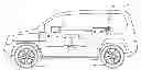
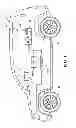
FIG. 1 is a schematic view of a vehicle with an auxiliary system;
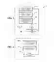
FIG. 2 is a schematic block diagram of an algorithm for operation of the auxiliary system according to one non-limiting embodiment;
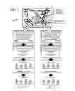
FIG. 3 is a series of pages displayed on a vehicle display in accordance with the schematic block diagram of FIG. 2;
FIG. 4 is a schematic block diagram of an algorithm for operation of the auxiliary system according to one non-limiting embodiment; and
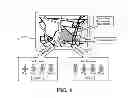
FIG. 5 is a series of pages displayed on a vehicle display in accordance with the schematic block diagram of FIG. 4.
DETAILED DESCRIPTION
FIG. 1 schematically illustrates selected portions of an auxiliary system 10. The auxiliary system 10 generally includes a control subsystem 12, a vehicle support subsystem 14 such as a tire pressure control subsystem and a Global Positioning System (GPS) subsystem 16. The auxiliary system 10 may be utilized within a ground vehicle 18 with four tires 20, however, other vehicles such as tactical wheeled vehicles, farm vehicles, construction vehicles and other vehicle types will also benefit herefrom. Although a tire pressure control subsystem is illustrated in the disclosed, non-limiting embodiment, it should be understood that other vehicle auxiliary subsystems such as, but not limited to, a suspension system, a suspension damping system, a braking system, a drive train system, a stability control system, a torque management system, a ride height adjustment system, a transmission system, a traction control system, and the like.
The control subsystem 12 generally includes a control module 22 with a processor 24, a memory 26, and an interface 28. The processor 24 may be any type of microprocessor having desired performance characteristics. The memory 26 may include any type of computer readable medium which stores the data and control algorithms described herein such as a terrain database 30, and a GPS enabled support system algorithm 32 (FIGS. 2 and 3). The functions of the algorithm 32 are disclosed in terms of functional block diagrams, and it should be understood by those skilled in the art with the benefit of this disclosure that these functions may be enacted in either dedicated hardware circuitry or programmed software routines capable of execution in a microprocessor based electronics control embodiment. In one non-limiting embodiment, the control module 22 may be a portion of a central vehicle control, a stand-alone unit or other system. Other operational software for the processing module may also be stored in memory device. The interface 28 facilitates communication with other subsystems such as a display 34, a user interface 36, the vehicle support subsystem 14 and the GPS subsystem 16. It should be understood that the interface 28 may also include communication with sensor systems such as vehicle weight sensors and other data inputs such as weather information.
The terrain database 30 may be stored in the memory 26 in addition to conventional GPS databases which include roads, trails, bodies of water, points of interest, etc., also includes in the disclosed non-limiting embodiment, terrain conditions and the location thereof. Terrain conditions as described herein may include the types of terrain, e.g., sand, swamp, soil, rocks, etc. The terrain database 30 may also include terrain mechanics such as density, depth etc. The terrain database 30 may also be pertinent and calibrated with respect to particulars of the vehicle support subsystem 14 such as tire pressure for particular types of terrain as it is usually desirable to lower tire pressure for lower density terrain, e.g., low pressure for sand and high pressure for pavement.
With reference to FIGS. 2 and 3, operation of the auxiliary system 10 according to one disclosed non-limiting embodiment, generally includes identifying a vehicle location with respect to a terrain condition (step 100). That is, the GPS subsystem 16 compares the vehicle position to the terrain database 30 to determine the vehicle's position relative the types of terrain stored in the terrain database 30. It should be appreciated that the GPS subsystem provides typical display options and that the terrain database 30 may, for example, be overlaid thereon. The terrain database 30 may alternatively or additionally receive information regarding terrain conditions from external sources as well as being pre-programmed therewith.
When the vehicle position is identified as directed toward a change in terrain condition, the auxiliary system 10 identifies the potential entry (Step 110) then alerts the operator and requests change to the vehicle support subsystem 14 (Step 120). The algorithm 32 may utilize a recursive algorithm to determine if the vehicle will enter a new terrain zone should the vehicle continue on its present velocity vector. It should be understood that various tolerances and control procedures may be provided to avoid unnecessary alerts.
If the operator affirms the desire to change the vehicle support subsystem 14 (Step 130), the auxiliary system 10 then provide the required instruction on the display 34. The auxiliary system 10 then changes the condition of the vehicle support subsystem 14 (Step 140).
With reference to FIGS. 4 and 5, operation of the auxiliary system 10 according to another disclosed non-limiting embodiment, generally includes identifying a vehicle location with respect to a terrain condition (step 200); identifies the entry or exit (Step 210) then automatically changes the condition of the vehicle support subsystem 14 (Step 220). Such automatic change in the vehicle support subsystem 14 may be particularly applicable to military, construction and farm type vehicles which may not have the regulatory restrictions of civilian passenger vehicles. The auxiliary system 10 may alternatively or additionally be combined with an audible and/or visual warning.
A system and method has been disclosed for control of vehicle characteristics based at least in part on terrain based on global positioning system (GPS) data, current weather information, and historical weather information.
It should be understood that relative positional terms such as “forward,” “aft,” “upper,” “lower,” “above,” “below,” and the like are with reference to the normal operational attitude of the vehicle and should not be considered otherwise limiting.
Although the different non-limiting embodiments have specific illustrated components, the embodiments of this invention are not limited to those particular combinations. It is possible to use some of the components or features from any of the non-limiting embodiments in combination with features or components from any of the other non-limiting embodiments.
It should be understood that like reference numerals identify corresponding or similar elements throughout the several drawings. It should also be understood that although a particular component arrangement is disclosed in the illustrated embodiment, other arrangements will benefit herefrom.
Although particular step sequences are shown, described, and claimed, it should be understood that steps may be performed in any order, separated or combined unless otherwise indicated and will still benefit from the present disclosure.
The foregoing description is exemplary rather than defined by the limitations within. Various non-limiting embodiments are disclosed herein, however, one of ordinary skill in the art would recognize that various modifications and variations in light of the above teachings will fall within the scope of the appended claims. It is therefore to be understood that within the scope of the appended claims, the disclosure may be practiced other than as specifically described. For that reason the appended claims should be studied to determine true scope and content.
Claims
What is claimed is:1. A system for a vehicle comprising:
a GPS subsystem; and
a vehicle support subsystem in communication with said GPS subsystem, said vehicle support subsystem operable in response to said GPS subsystem.
2. The system as recited in claim 1, further comprising a control subsystem in communication with said GPS subsystem and said vehicle support subsystem.
3. The system as recited in claim 1, wherein said control subsystem includes a display.
4. The system as recited in claim 3, wherein said control subsystem includes a user interface.
5. The system as recited in claim 1, wherein said vehicle support subsystem is a tire inflation subsystem.
6. The system as recited in claim 5, further comprising a terrain database.
7. A system for a vehicle comprising:
a GPS subsystem; and
a tire inflation subsystem in communication with said GPS subsystem, said tire inflation subsystem operable in response to said GPS subsystem.
8. The system as recited in claim 7, further comprising a control subsystem in communication with said GPS subsystem and said tire inflation subsystem.
9. The system as recited in claim 8, wherein said control subsystem includes a display.
10. The system as recited in claim 9, wherein said control subsystem includes a user interface.
11. The system as recited in claim 10, wherein said control subsystem includes a terrain database.
12. A method of operating a system for a vehicle comprising:
identifying a vehicle location with respect to a terrain condition using a GPS subsystem; and
operating a vehicle support subsystem with respect to the vehicle location.
13. The method as recited in claim 12, wherein operating the vehicle support subsystem further includes alerting an operator to the terrain condition.
14. The method as recited in claim 13, wherein operating the vehicle support subsystem further includes prompting the operator to adjust the vehicle support system.
15. The method as recited in claim 13, wherein operating the vehicle support subsystem further includes adjusting the vehicle support system.
16. The method as recited in claim 12, wherein operating the vehicle support subsystem further includes adjusting a tire pressure.
17. The method as recited in claim 12, wherein operating the vehicle support subsystem further includes adjusting the vehicle support system without operator input.
Images & Drawings included:
Sources:
- United States Patent and Trademark Office - verify current appl. status at the USPTO↗
Recent applications in this class:
- » 20240338417 2024-10-10
System and Method for Use of Pattern Recognition in Assessing or Monitoring Vehicle Status or Operator Driving Behavior - » 20240202272 2024-06-20
DISTRIBUTION BACKBONE - » 20230281264 2023-09-07
System and method for use of pattern recognition in assessing or monitoring vehicle status or operator driving behavior - » 20210216607 2021-07-15
Distribution Backbone - » 20210192008 2021-06-24
COLLABORATIVE INCIDENT MEDIA RECORDING SYSTEM - » 20210173891 2021-06-10
System and Method for Use of Pattern Recognition in Assessing or Monitoring Vehicle Status or Operator Driving Behavior - » 20200401649 2020-12-24
Systems and methods for removing unwanted interactions in quantum devices - » 20200125626 2020-04-23
System and method for use of pattern recognition in assessing or monitoring vehicle status or operator driving behavior - » 20200125625 2020-04-23
Systems and methods for removing unwanted interactions in quantum devices - » 20190272305 2019-09-05
Correction of angular error of plane-of-incidence azimuth of optical metrology device
Recent applications for this Assignee:
- » 20240013587 2024-01-11
Partial sensor data sharing for connected vehicles - » 20230219580 2023-07-13
Driver and vehicle monitoring feedback system for an autonomous vehicle - » 20220215698 2022-07-07
Partial sensor data sharing for connected vehicles - » 20220126850 2022-04-28
SYSTEM AND METHOD FOR DETERMINING DRIVER PREFERENCES FOR AUTONOMOUS VEHICLES - » 20210257138 2021-08-19
Inductor with variable permeability core - » 20210182739 2021-06-17
ENSEMBLE LEARNING MODEL TO IDENTIFY CONDITIONS OF ELECTRONIC DEVICES - » 20210161029 2021-05-27
Systems and methods for additive manufacturing of wick structure for vapor chamber - » 20210127242 2021-04-29
Vehicular communications based on internet communication identifiers associated with codes of vehicles - » 20210124009 2021-04-29
Triangulation and calibration of electronic control units - » 20210118243 2021-04-22
Vehicular communications through identifiers and online systems