Imaging lens
US20140118847A1
2014-05-01
14/062,429
2013-10-24
✅ Patent granted
US 8,970,970 B2
2015-03-03
-
-
Evelyn A. Lester
Saliwanchik, Lloyd & Eisenschenk
2033-10-24
Abstract:
An exemplary embodiment of the present invention relates to an imaging lens, the imaging lens including, in an ordered way from an object side, a first lens having positive (+) refractive power, a second lens having negative (−) refractive power, a third lens having positive (+) refractive power, a fourth lens having negative (−) refractive power, and a fifth lens having a negative (−) refractive power, wherein the third lens takes a meniscus shape convexly formed at an object side.
Assignee:
- LG INNOTEK, CO., LTD. 5,701 🇰🇷 Seoul, South Korea
Applicant:
Interested in similar patents?
Get notified when new applications in this technology area are published.
Classification:
G02B9/60 » CPC main
Optical objectives characterised both by the number of the components and their arrangements according to their sign, i.e. + or - having five components only
G02B13/18 » CPC further
Optical objectives specially designed for the purposes specified below with lenses having one or more non-spherical faces, e.g. for reducing geometrical aberration
G02B3/02 IPC
Simple or compound lenses with non-spherical faces
Description
This application claims the benefit under 35 U.S.C. §119 of Korean Patent Application No. 10-2012-0118795, filed Oct. 25, 2012, which is hereby incorporated by reference in its entirety.
BACKGROUND
1. Field of the Invention
The teachings in accordance with exemplary embodiments of this disclosure relate generally to an imaging lens.
2. Description of Related Art
Recently, vigorous research efforts are being made in the fields of a mobile phone-purpose camera module, a digital still camera (DSC), a camcorder, and a PC camera (an imaging device attached to a person computer), all connected with an image pick-up system. One of the most important components in order that a camera module related to such image pickup system obtains an image is a lens producing an image.
The mobile phones are being recently miniaturized and thinned in thickness thereof, and mounted with components for performing various functions.
As a result, the reality is that various researches and development are being waged to pursue miniaturization of an imaging lens of a camera module for mobile phones.
BRIEF SUMMARY
Exemplary embodiments of the present disclosure provide a bright lens optical system configured to realize miniaturization and high resolution.
In one general aspect of the present disclosure, there is provided an imaging lens, the imaging lens comprising: in an ordered way from an object side, a first lens having positive (+) refractive power;
a second lens having negative (−) refractive power;
a third lens having positive (+) refractive power;
a fourth lens having positive (+) refractive power: and
a fifth lens having negative (−) refractive power, wherein the third lens takes a meniscus shape convexly formed to an object side.
Preferably, but not necessarily, the first lens may take a meniscus shape convexly formed at both surfaces to an object side.
Preferably, but not necessarily, the second lens may take a concave shape.
Preferably, but not necessarily, the fourth lens may take a meniscus shape.
Preferably, but not necessarily, the first, second, third, fourth and fifth lenses may be aspherical at one surface or both surfaces.
Preferably, but not necessarily, one surface or all surfaces of the first, second, third, fourth and fifth lenses may be formed with one or more inflection points.
Preferably, but not necessarily, the imaging lens may meet a conditional expression of 1.0<ΣT/f<1.5, where f is a focal length of an optical system, and ΣT is a distance from an object side surface of the first lens to an image-forming surface.
Preferably, but not necessarily, the imaging lens may meet a conditional expression of 1.6<ΣN2&N3<1.7, where N2 and N3 are refractive indexes of the second and third lenses.
Preferably, but not necessarily, the imaging lens may meet a conditional expression of 1.5<N1&N4&N5<1.6, where N1, N4 and N5 are refractive indexes of the first, fourth and fifth lenses.
Preferably, but not necessarily, the imaging lens may meet a conditional expression of 20<V2&V3<30, where Abbe' numbers of second and third lenses are V2 and V3.
Preferably, but not necessarily, the imaging lens may meet a conditional expression of 50<V1&V4&V5<60, where Abbe' numbers of first, fourth and fifth lenses are V1, V4 and V5.
Preferably, but not necessarily, the imaging lens may meet a conditional expression of 3.6<ΣT<4.6, where ΣT is a distance from an object side surface of the first lens to an image-forming surface.
Preferably, but not necessarily, the imaging lens may meet a conditional expression of 2.0<F/#<3.0, where F-Number is F/#.
Preferably, but not necessarily, the imaging lens may meet a conditional expression of R5&R6>1, where R5 and R6 are respectively a radius of curvature of first surface and second surface of the third lens.
Preferably, but not necessarily, the imaging lens may meet a conditional expression of R5-R6<0, where R5 and R6 are respectively a radius of curvature of first surface and second surface of the third lens.
Preferably, but not necessarily, the imaging lens may meet a conditional expression of 0.7<(R3+R4)/(R3−R4)<1.0, where R3 and R4 are respectively a radius of curvature of first surface and second surface of the second lens.
Preferably, but not necessarily, the imaging lens may meet a conditional expression of 10.0<|(R5+R6)/(R5−R6)|<15.0, where R5 and R6 are respectively a radius of curvature of first surface and second surface of the third lens.
In another general aspect of the present disclosure, there is provided an imaging lens, the imaging lens comprising: in an ordered way from an object side, a first lens having positive (+) refractive power;
a second lens having negative (−) refractive power;
a third lens having positive (+) refractive power;
a fourth lens having positive (+) refractive power: and
a fifth lens having negative (−) refractive power, wherein the fourth lens takes a meniscus shape, and wherein the imaging lens meets a conditional expression of R5 & R6>1, where R5 and R6 are respectively a radius of curvature of first surface and second surface of the third lens.
Preferably, but not necessarily, the third lens may take a meniscus shape convexly formed at an object side.
Preferably, but not necessarily, the first lens may be positioned at a front end of an object side surface with an aperture.
The exemplary embodiments of the present disclosure can realize a bright optical system with miniaturized compact construction and high resolution by being configured with 5 (five) pieces of lenses.
BRIEF DESCRIPTION OF THE DRAWINGS
FIG. 1 is a constructional view illustrating a camera module lens according to an exemplary embodiment of the present disclosure.
FIGS. 2a and 2b are graphs measuring coma aberrations according to an exemplary embodiment of the present disclosure.
FIGS. 3 and 4 are graphs illustrating an aberration according to an exemplary embodiment of the present disclosure, where longitudinal spherical aberration, astigmatic field curves and distortion are measured, in order from left side.
FIGS. 5a and 5b are graphs illustrating MTF (Modulation Transfer Function) characteristics relative to spatial frequency at a lens position according to an exemplary embodiment of the present disclosure.
FIGS. 6a and 6b are graphs illustrating characteristics of diffraction MTF (Modulation Transfer Function) at a lens position according to an exemplary embodiment of the present disclosure.
DETAILED DESCRIPTION
Exemplary embodiments of the present disclosure will be described in detail with reference to the accompanying drawings.
FIG. 1 is a constructional view illustrating a camera module lens according to an exemplary embodiment of the present disclosure.
The camera module lens according to an exemplary embodiment of the present disclosure is arranged with an imaging lens comprised of a plurality of lenses with respect to an optical axis. In the constructional view of FIG. 1, relative thickness, size and shape of a lens may be exaggerated or reduced for clarity and explanations throughout, and spherical or aspherical shape may be proposed as an example, and therefore the shape is not limited thereto.
Referring to FIG. 1, the camera lens module may be arranged with, in an ordered way from an object side, an aperture, a first lens (10), a second lens (20), a third lens (30), a fourth lens (40), a fifth lens (50), a filter (60), a cover glass and a photo-detector (70).
Light corresponding to image information of a subject is incident on the photo-detector (70) by passing the first lens (10), the second lens (20), the third lens (30), the fourth lens (40), the filter (60) and the cover glass.
Hereinafter, in the description of the construction of each lens, an “object side surface” means a surface of a lens facing an object side with respect to an optical axis, and an “image side surface” means a surface of the lens facing a capturing surface with respect to the optical axis.
The first lens (10) may have a positive (+) refractive power, the second lens (20) may have a negative (−) refractive power, the third lens (30) may have a positive (+) refractive power, the fourth lens (40) may have a positive (+) refractive power, and the fifth lens (50) may have a negative (−) refractive power.
At this time, the first lens (10) may take a meniscus shape convexly formed at both surfaces to an object side, and the first lens (10) may be positioned at a front end of an object side surface with an aperture.
Furthermore, the second lens (20) may take a concave shape and the third lens (30) may take a meniscus shape convexly formed at both surfaces to an image side, and the fourth lens (40) may take a meniscus shape.
Furthermore, the first, second, third, fourth and fifth lenses (10, 20, 30, 40, 50) may be aspherical at both surfaces. In addition, one surface or all surfaces of the first, second, third, fourth and fifth lenses are formed with one or more inflection points. Hence, the exemplary embodiments of the present disclosure can realize a bright optical system with miniaturized compact construction and high resolution by being configured with 5 (five) pieces of lenses.
For information, ‘S1 and ‘S2’ of FIG. 1 are respectively an object side surface and an image side surface of the first lens (10), ‘S3’ and ‘S4’ are respectively an object side surface and an image side surface of the second lens(20), ‘S5’ and ‘S6’ are respectively an object side surface and an image side surface of the third lens(30), ‘S7’ and ‘S8’ are respectively an object side surface and an image side surface of the fourth lens(40), ‘S9’ and ‘S10’ are respectively an object side surface and an image side surface of the fifth lens (50), and ‘S11’ and ‘S12’ are respectively an object side surface and an image side surface of the filter (60).
The filter (60) may be any one optical filter selected from an infrared filter and a cover glass. If the infrared filter is applied for the camera module, the infrared filter blocks infrared ray emitted from external light from being transferred to the photo-detector (70). Furthermore, the infrared filter transmits visible light, reflects infrared ray and outputs the reflected infrared ray to the outside.
The photo-detector (70) may be an image sensor including CCD (Charge Coupled Device) or CMOS (Complementary Metal Oxide Semiconductor), for example.
Because the later-described conditional expressions and exemplary embodiments are preferred embodiments enhancing an effect of interaction, it would be obvious to those skilled in the art that the present disclosure is not necessarily comprised of the following conditions. For example, only by satisfying some conditions of later-described conditional expressions, the lens construction (framework) of the present disclosure may have an enhanced effect of interaction.
1.0<ΣT/f<1.5 [Conditional expression 1]
1.6<N2&N3<1.7 [Conditional expression 2]
1.5<N1&N4&N5<1.6 [Conditional expression 3]
20<V2&V3<30 [Conditional expression 4]
50<V1&V4&V5<60 [Conditional expression 5]
3.6<ΣT<4.6 [Conditional expression 6]
2.0<F/#<3.0 [Conditional expression 7]
R5&R6>1 [Conditional expression 8]
R5−R6<0 [Conditional expression 9]
0.7<(R3+R4)/(R3−R4)<1.0 [Conditional expression 10]
10.0<|(R5+R6)/(R5−R6)|<15.0, [Conditional expression 11]
where, f: a focal length of an optical system
f1,f2,f3,f4,f5: focal lengths of first, second, third, fourth and fifth lenses
ΣT: a distance from an object side surface of the first lens to an image-forming surface.
N1,N2,N3,N4,N5: refractive indexes of the first, second, third, fourth and fifth lenses
V1,V2,V3,V4,V5: Abbe's numbers of the first, second, third, fourth and fifth lenses
F/#:F-Number
R3: radius of curvature of first surface of the second lens
R4: radius of curvature of second surface of the second lens
R5: radius of curvature of first surface of the third lens
R6: radius of curvature of second surface of the third lens
Hereinafter, the action and effect of the present disclosure will be described with reference to a specific exemplary embodiment. Aspheric mentioned in a later-exemplary embodiment is obtained from a known Equation 1, and ‘E and its succeeding number’ used in Conic constant k and aspheric coefficient A, B, C, D, E, F indicates 10's power. For example, E+01 denotes 101, and E−02 denotes 10−2.
z = cY 2 1 + 1 - ( 1 + K ) c 2 Y 2 + AY 4 + BY 4 + CY 4 + DY 4 + EY 4 + FY 4 + … [ Equation 1 ]
where, z: a distance from the lens's top-point to an optical axis direction,
c: basic curvature of a lens, Y: a distance towards a direction perpendicular to an optical axis, K: Conic constant, and A, B, C, D, E, F: aspheric coefficients
EXEMPLARY EMBODIMENTS
The following Table 1 shows an exemplary embodiment matching the aforementioned conditional expressions.
| TABLE 1 | |||
| Exemplary | Exemplary | ||
| embodiment | embodiment | ||
| F | 3.13 | N1 | 1.53 | |
| F1 | 2.37 | V1 | 56.5 | |
| F2 | −3.34 | N2 | 1.65 | |
| F3 | 23.84 | V2 | 23.0 | |
| f4 | 2.13 | N3 | 1.65 | |
| f5 | −2.25 | V3 | 23.0 | |
| ΣT | 4.00 | N4 | 1.53 | |
| V4 | 56.5 | |||
| N5 | 1.53 | |||
| V5 | 56.5 | |||
Referring to Table 1, it can be noted that N2 and N3 are 1.65 that matches the conditional expression 2, and V2 and V3 are 23 that matches the conditional expression 4.
The following Table 2 shows an exemplary embodiment which is a more detailed exemplary embodiment over that of Table 1.
| TABLE 2 | ||||
| Surface | Radius of | Thickness or | Refractive | |
| number | curvature (R) | distance (d) | index (N) | materials |
| STOP* | 1.50 | 0.50 | 1.53 | Plastic |
| 2* | −6.92 | 0.10 | ||
| 3* | −18.37 | 0.27 | 1.65 | Plastic |
| 4* | 2.46 | 0.19 | ||
| 5* | 2.94 | 0.29 | 1.65 | Plastic |
| 6* | 3.49 | 0.26 | ||
| 7* | −2.46 | 0.57 | 1.53 | Plastic |
| 8* | −0.84 | 0.10 | ||
| 9* | 2.88 | 0.47 | 1.53 | Plastic |
| 10 | 0.80 | 0.83 | ||
| 11 | INFINITY | 0.30 | 1.53 | IR-filter |
| 12 | INFINITY | 0.12 | ||
| 0.22 | ||||
| image | INFINITY | 0.00 | ||
| 0.00 | ||||
The notation * in the above Table 2 and following Table 3, which is further written near the surface number indicates aspheric. The following Table 3 shows a value of aspheric coefficient of each lens in the exemplary embodiment of Table 2.
| TABLE 3 | ||||||
| Surface | ||||||
| number | k | A | B | C | D | E |
| 1* | −0.4602 | −0.0192 | 0.0339 | −0.4302 | 0.7779 | 1.0008 |
| 2* | 44.8693 | 0.0075 | −0.0545 | −0.7402 | 0.9667 | 0.4718 |
| 3* | 482.9808 | 0.0641 | 0.0479 | −0.9548 | 1.1833 | 0.0668 |
| 4* | −29.0347 | 0.1811 | −0.0218 | −0.3132 | 0.3122 | 0.0363 |
| 5* | 0.0000 | −0.2772 | 0.1203 | 0.0707 | −0.0516 | 0.0112 |
| 6* | 0.0000 | −0.1140 | −0.1400 | 0.2783 | −0.3014 | .2261 |
| 7* | 1.4856 | 0.2275 | −0.1719 | 0.0342 | −0.0661 | .0697 |
| 8* | −0.7762 | 0.3883 | −0.2344 | 0.1036 | 0.0475 | 0.0358 |
| 9* | −102.0643 | −0.0896 | −0.0495 | 0.0616 | −0.0178 | .0015 |
| 10* | −6.2540 | −0.1147 | 0.0463 | −0.0161 | 0.0031 | 0.0002 |
FIGS. 2a and 2b are graphs measuring coma aberrations according to an exemplary embodiment of the present disclosure, where tangential aberration and sagittal aberration of each wavelength based on a field height are measured. In FIG. 2, it is interpreted that a coma aberration correcting function is good as curves approach the X axis from a positive axis and a negative axis. In the measurement exemplary embodiments of FIG. 2, because values of images in nearly all fields proximate to the X axis, coma aberration correction function demonstrates a superior figure.
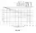
FIGS. 3 and 4 are graphs illustrating an aberration according to an exemplary embodiment of the present disclosure, where longitudinal spherical aberration, astigmatic field curves and distortion are measured, in order from left side.
In FIGS. 3 and 4, a Y axis means size of an image, and an X axis means focal length (unit: mm) and distortion degree (unit: %). In FIG. 3, it is interpreted that an aberration correcting function is good as curves approach the Y axis. In the shown aberration diagram, because values of images in nearly all fields appear proximate to the Y axis, spherical aberration, astigmatic aberration and distortion aberration all demonstrate a superior figure.
First, FIG. 3 illustrates a graph illustrating an aberration at an infinity location, where a range of the longitudinal spherical aberration is −0.008 mm˜+0.012 mm, a range of astigmatic aberration is −0.021 mm˜+0.016 mm, and a range of distortion aberration is 0 mm˜+1.5 mm.
FIG. 4 illustrates a graph illustrating an aberration at 10 cm location, where a range of the longitudinal spherical aberration is −0.006 mm˜+0.017 mm, a range of astigmatic aberration is −0.022 mm˜+0.020 mm, and a range of distortion aberration is 0 mm˜+1.4 mm, such that the imaging lens according to the exemplary embodiments of the present disclosure can correct the characteristics of spherical aberration, astigmatic aberration and distortion aberration, whereby the imaging lens according to the exemplary embodiment of the present invention has an excellent lens characteristics.
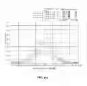
FIGS. 5a and 5b are graphs illustrating MTF (Modulation Transfer Function) characteristics relative to spatial frequency at a lens position according to an exemplary embodiment of the present disclosure, where the MTF characteristics depending on changes in spatial frequency (cycle/mm) were measured. At this time, the MTF characteristics are ratio values that have calculated a difference of images captured after light having started from a surface of an original object passes through a lens, where if an MTF value is ‘1’, it is the most ideal, and the MTF value decreases, the resolution deteriorates.
Because all MTF values are measured high, in a case where a lens position is infinity as in FIG. 5a, and in a case where a lens position is 10 cm as in FIG. 5b, the imaging lens according to the exemplary embodiment of the present invention has an excellent optical characteristics.
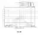
FIGS. 6a and 6b are graphs illustrating characteristics of diffraction MTF (Modulation Transfer Function) at a lens position according to an exemplary embodiment of the present disclosure, where FIG. 6a is a graph illustrating a lens position at infinity, and FIG. 6b is a graph illustrating a lens position of 10 cm. Thus, the frequency is 227 c/mm, which is a through-focus MTF.
The previous description of the present disclosure is provided to enable any person skilled in the art to make or use the invention. Various modifications to the invention will be readily apparent to those skilled in the art, and the generic principles defined herein may be applied to other variations without departing from the spirit or scope of the invention. Thus, the invention is not intended to limit the examples described herein, but is to be accorded the widest scope consistent with the principles and novel features disclosed herein.
Claims
What is claimed is:1. An imaging lens, the imaging lens comprising: in an ordered way from an object side, a first lens having positive (+) refractive power;
a second lens having negative (−) refractive power;
a third lens having positive (+) refractive power;
a fourth lens having positive (+) refractive power: and
a fifth lens having negative (−) refractive power, wherein the third lens takes a meniscus shape convexly formed to an object side.
2. The imaging lens of claim 1, wherein the first lens takes a meniscus shape convexly formed at both surfaces to an object side.
3. The imaging lens of claim 1, wherein the second lens takes a concave shape.
4. The imaging lens of claim 1, wherein the fourth lens takes a meniscus shape.
5. The imaging lens of claim 1, wherein the first, second, third, fourth and fifth lenses are aspherical at one surface or both surfaces.
6. The imaging lens of claim 1, wherein one surface or all surfaces of the first, second, third, fourth and fifth lenses are formed with one or more inflection points.
7. The imaging lens of claim 1, wherein the imaging lens meets a conditional expression of 1.0<ΣT/f<1.5, where f is a focal length of an optical system, and ΣT is a distance from an object side surface of the first lens to an image-forming surface.
8. The imaging lens of claim 1, wherein the imaging lens meets a conditional expression of 1.6<N2&N3<1.7, where N2 and N3 are refractive indexes of the second and third lenses.
9. The imaging lens of claim 1, wherein the imaging lens meets a conditional expression of 1.5<N1&N4&N5<1.6, where N1, N4 and N5 are refractive indexes of the first, fourth and fifth lenses.
10. The imaging lens of claim 1, wherein the imaging lens meets a conditional expression of 20<V2&V3<30, where Abbe' numbers of second and third lenses are V2 and V3.
11. The imaging lens of claim 1, wherein the imaging lens meets a conditional expression of 50<V1&V4&V5<60, where Abbe' numbers of first, fourth and fifth lenses are V1, V4 and V5.
12. The imaging lens of claim 1, wherein the imaging lens meets a conditional expression of 3.6<ΣT<4.6, where ΣT is a distance from an object side surface of the first lens to an image-forming surface.
13. The imaging lens of claim 1, wherein the imaging lens meets a conditional expression of 2.0<F/#<3.0, where F-Number is F/#.
14. The imaging lens of claim 1, wherein the imaging lens meets a conditional expression of R5&R6>1, where R5 and R6 are respectively a radius of curvature of first surface and second surface of the third lens.
15. The imaging lens of claim 1, wherein the imaging lens meets a conditional expression of R5−R6<0, where R5 and R6 are respectively a radius of curvature of first surface and second surface of the third lens.
16. The imaging lens of claim 1, wherein the imaging lens meets a conditional expression of 0.7<(R3+R4)/(R3−R4)<1.0, where R3 and R4 are respectively a radius of curvature of first surface and second surface of the second lens.
17. The imaging lens of claim 1, wherein the imaging lens meets a conditional expression of 10.0<|(R5+R6)/(R5−R6)|<15.0, where R5 and R6 are respectively a radius of curvature of first surface and second surface of the third lens.
18. An imaging lens, the imaging lens comprising: in an ordered way from an object side, a first lens having positive (+) refractive power;
a second lens having negative (−) refractive power;
a third lens having positive (+) refractive power;
a fourth lens having positive (+) refractive power: and
a fifth lens having negative (−) refractive power, wherein the fourth lens takes a meniscus shape, and wherein the imaging lens meets a conditional expression of R5&R6>1, where R5 and R6 are respectively a radius of curvature of first surface and second surface of the third lens.
19. The imaging lens of claim 18, wherein the third lens takes a meniscus shape convexly formed at an object side.
20. The imaging lens of claim 18, wherein the first lens is positioned at a front end of an object side surface with an aperture.
Images & Drawings included:


Sources:
- United States Patent and Trademark Office - verify current appl. status at the USPTO↗
Similar patent applications:
- » 20090225215
Diffractive imaging lens, diffractive imaging lens optical system, and imaging apparatus using the diffractive imaging lens optical system - » 20110085071
Image pickup lens comprising aperture stop and single lens, image pickup module comprising image pickup lens including aperture stop and single lens, method for manufacturing image pickup lens comprising aperture stop and single lens, and method for manufacturing image pickup module comprising image pickup lens including aperture stop and single lens - » 20110211263
Imaging lens, optical apparatus including imaging lens and method for manufacturing imaging lens - » 20110170195
IMAGING LENS, OPTICAL APPARATUS INCLUDING IMAGING LENS AND METHOD FOR MANUFACTURING IMAGING LENS - » 20120026590
Imaging lens, optical apparatus including imaging lens and method for manufacturing imaging lens - » 20120127590
Imaging lens, optical apparatus equipped with imaging lens and method for manufacturing imaging lens - » 20120183288
Image capture lens, wafer lens, wafer lens laminate, method of manufacturing image capture lens, image capture lens intermediate product, method of manufacturing image capture lens intermediate product - » 20120019938
CURABLE RESIN COMPOSITION FOR CEMENTED LENS, IMAGING LENS, AND METHOD FOR MANUFACTURING IMAGING LENS - » 20210247549
Meta-lens, image capturing lens including the meta-lens, image capturing device including the image capturing lens, and electronic apparatus including the image capturing device - » 20240337775
META-LENS, IMAGE CAPTURING LENS INCLUDING THE META-LENS, IMAGE CAPTURING DEVICE INCLUDING THE IMAGE CAPTURING LENS, AND ELECTRONIC APPARATUS INCLUDING THE IMAGE CAPTURING DEVICE
Recent applications in this class:
- » 20250291154 2025-09-18
PHOTOGRAPHY OPTICAL LENS ASSEMBLY, IMAGE CAPTURING UNIT AND ELECTRONIC DEVICE - » 20250251569 2025-08-07
Optical Imaging Lens Assembly - » 20250244560 2025-07-31
OPTICAL IMAGING SYSTEM - » 20250199268 2025-06-19
IMAGING OPTICAL LENS ASSEMBLY, IMAGE CAPTURING APPARATUS AND ELECTRONIC DEVICE - » 20250189760 2025-06-12
OPTICAL SYSTEM, AND OPTICAL MODULE AND CAMERA MODULE COMPRISING SAME - » 20250147275 2025-05-08
IMAGING LENS SYSTEM AND CAMERA MODULE - » 20250147274 2025-05-08
OPTICAL IMAGING LENS ASSEMBLY, IMAGING APPARATUS AND ELECTRONIC DEVICE - » 20250085509 2025-03-13
OPTICAL SYSTEM, OPTICAL APPARATUS, AND METHOD FOR MANUFACTURING OPTICAL SYSTEM - » 20250076611 2025-03-06
ZOOM LENS, OPTICAL APPARATUS, AND METHOD FOR MANUFACTURING ZOOM LENS - » 20250044552 2025-02-06
PHOTOGRAPHING OPTICAL LENS SYSTEM, IMAGING APPARATUS AND ELECTRONIC DEVICE
Recent applications for this Assignee:
- » 20250286443 2025-09-11
MOTOR - » 20250286280 2025-09-11
ANTENNA SUBSTRATE - » 20250284091 2025-09-11
LENS DRIVING APPARATUS, CAMERA MODULE, AND OPTICAL DEVICE - » 20250284090 2025-09-11
LENS DRIVING DEVICE, AND CAMERA MODULE AND OPTICAL DEVICE INCLUDING SAME - » 20250282381 2025-09-11
SYSTEM, METHOD, AND COMPUTER PROGRAM PRODUCT FOR DYNAMIC DETECTION THRESHOLD FOR LIDAR OF AN AUTONOMOUS VEHICLE - » 20250282244 2025-09-11
DEVICE AND METHOD FOR CHARGING ELECTRIC VEHICLE WITH DIFFERENT CHARGING STANDARDS - » 20250276601 2025-09-04
DEVICE AND METHOD FOR CHARGING ELECTRIC VEHICLE WITH DIFFERENT CHARGING STANDARDS - » 20250267369 2025-08-21
CAMERA MODULE AND OPTICAL DEVICE INCLUDING THE SAME CAPABLE OF PERFORMING ACCURATE OIS FEEDBACK OPERATION - » 20250267352 2025-08-21
CAMERA MODULE - » 20250264694 2025-08-21
OPTICAL SYSTEM AND CAMERA MODULE INCLUDING SAME