EXTRUDER SCREW WITH CHANNEL
US20140119153A1
2014-05-01
13/661,392
2012-10-26
Abstract:
An extruder apparatus is disclosed and which includes a cylindrical barrel having a feed end and a discharge end, the feed end having an outlet in fluid communication with a feed box. The extruder screw is mounted in the cylindrical barrel, and the screw has an outer surface having one or more helical flights mounted thereon. The screw has a discharge end and a terminal end, wherein the screw further comprising a notch at the terminal end.
Inventors:
- Patrice De Monte 8 🇧🇪 Arlon, Belgium
- Ernest Wilford Looman, JR. 6 🇺🇸 Tallmadge, OH, United States
- Warren Paul Ripple 5 🇺🇸 North Canton, OH, United States
- Malcolm George Marshall 2 🇺🇸 Wadsworth, OH, United States
Interested in similar patents?
Get notified when new applications in this technology area are published.
Classification:
B29B7/42 » CPC main
Mixing; Kneading continuous, with mechanical mixing or kneading devices with movable mixing or kneading devices rotary with single shaft with screw or helix
B29C48/271 » CPC further
Extrusion moulding, i.e. expressing the moulding material through a die or nozzle which imparts the desired form; Apparatus therefor; Component parts, details or accessories; Auxiliary operations; Cleaning; Purging; Avoiding contamination of feeding units
B29C48/2888 » CPC further
Extrusion moulding, i.e. expressing the moulding material through a die or nozzle which imparts the desired form; Apparatus therefor; Component parts, details or accessories; Auxiliary operations; Feeding the extrusion material to the extruder in solid form, e.g. powder or granules in band or in strip form, e.g. rubber strips
B29C48/397 » CPC further
Extrusion moulding, i.e. expressing the moulding material through a die or nozzle which imparts the desired form; Apparatus therefor; Component parts, details or accessories; Auxiliary operations; Means for plasticising or homogenising the moulding material or forcing it through the nozzle or die using screws surrounded by a cooperating barrel, e.g. single screw extruders using a single screw
B29C48/56 » CPC further
Extrusion moulding, i.e. expressing the moulding material through a die or nozzle which imparts the desired form; Apparatus therefor; Component parts, details or accessories; Auxiliary operations; Means for plasticising or homogenising the moulding material or forcing it through the nozzle or die; Details of extruders; Screws having grooves or cavities other than the thread or the channel
B29C48/65 » CPC further
Extrusion moulding, i.e. expressing the moulding material through a die or nozzle which imparts the desired form; Apparatus therefor; Component parts, details or accessories; Auxiliary operations; Means for plasticising or homogenising the moulding material or forcing it through the nozzle or die; Details of extruders; Screws; Screws with two or more threads neighbouring threads or channels having different configurations, e.g. one thread being lower than its neighbouring thread
B29C48/655 » CPC further
Extrusion moulding, i.e. expressing the moulding material through a die or nozzle which imparts the desired form; Apparatus therefor; Component parts, details or accessories; Auxiliary operations; Means for plasticising or homogenising the moulding material or forcing it through the nozzle or die; Details of extruders; Screws; Screws with two or more threads having three or more threads
B29C48/92 » CPC further
Extrusion moulding, i.e. expressing the moulding material through a die or nozzle which imparts the desired form; Apparatus therefor; Component parts, details or accessories; Auxiliary operations Measuring, controlling or regulating
B29C48/022 » CPC further
Extrusion moulding, i.e. expressing the moulding material through a die or nozzle which imparts the desired form; Apparatus therefor characterised by the choice of material
B29C48/507 » CPC further
Extrusion moulding, i.e. expressing the moulding material through a die or nozzle which imparts the desired form; Apparatus therefor; Component parts, details or accessories; Auxiliary operations; Means for plasticising or homogenising the moulding material or forcing it through the nozzle or die; Details of extruders; Screws characterised by the material or their manufacturing process
B29C48/605 » CPC further
Extrusion moulding, i.e. expressing the moulding material through a die or nozzle which imparts the desired form; Apparatus therefor; Component parts, details or accessories; Auxiliary operations; Means for plasticising or homogenising the moulding material or forcing it through the nozzle or die; Details of extruders; Screws characterised by details of the thread, i.e. the shape of a single thread of the material-feeding screw the thread being discontinuous
B29C48/645 » CPC further
Extrusion moulding, i.e. expressing the moulding material through a die or nozzle which imparts the desired form; Apparatus therefor; Component parts, details or accessories; Auxiliary operations; Means for plasticising or homogenising the moulding material or forcing it through the nozzle or die; Details of extruders; Screws; Screws with two or more threads neighbouring threads and channels having identical configurations
B29C2948/9279 » CPC further
Indexing scheme relating to extrusion moulding; Measuring, controlling or regulating; Controlled parameter Errors or malfunctioning, e.g. for quality control
B29C2948/92876 » CPC further
Indexing scheme relating to extrusion moulding; Measuring, controlling or regulating; Location or phase of control; Extrusion unit Feeding, melting, plasticising or pumping zones, e.g. the melt itself
B29C2948/92885 » CPC further
Indexing scheme relating to extrusion moulding; Measuring, controlling or regulating; Location or phase of control; Extrusion unit; Feeding, melting, plasticising or pumping zones, e.g. the melt itself Screw or gear
B29C2948/92895 » CPC further
Indexing scheme relating to extrusion moulding; Measuring, controlling or regulating; Location or phase of control; Extrusion unit; Feeding, melting, plasticising or pumping zones, e.g. the melt itself Barrel or housing
B29B7/80 IPC
Mixing; Kneading Component parts, details or accessories; Auxiliary operations
Description
FIELD OF THE INVENTION
The invention relates in general to extruders for rubber processing, and more particularly to an extruder screw.
BACKGROUND OF THE INVENTION
It is known in the art to extrude visco-elastic materials such as rubber, using a screw extruder. It is known in the art to utilize a feedbox to feed slabs of rubber compound into the extruder. One problem that may occur is that the slab of rubber will shear off due to slab feed tension, commonly referred to as slab “bite off”. This typically occurs when low strength compounds are utilized, particularly tread compounds. The problem is worsened by the “scissors” action on the screw flights against the feed roll and feedbox. If the feed strip breaks, it will result in workers having to clean out the feed box. Thus it is desired to have an improved extruder screw that overcomes the slab bite off problem.
SUMMARY OF THE INVENTION
Definitions
Feed Hopper—typically a cone-shaped slab feed “chute” which attaches to the top of an extruder feedbox. The feed hopper establishes folds in the compound slab feeding into the extruder.
Feedbox—that area of an extruder, where the screw is exposed to accept a rubber slab feed. Typical cold feed extruders have a driven feed roll assembly which forms a pinch area with the screw flights and serves to pull slab compound through the feed hopper and fill the screw flights. The feed roll assembly is usually a hinged assembly, which can be opened for cleaning and greater maintenance access to the screw and feedbox.
Cold Feed Extruder—a piece of machinery for processing visco-elastic materials, including rubber. This machine accepts cold compound in slab form, warms the compound and moves the compound from the feedbox to the end of the barrel, by means of a rotating mechanical screw.
BRIEF DESCRIPTION OF THE DRAWINGS
The invention will be described by way of example and with reference to the accompanying drawings in which:
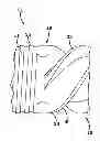
FIG. 1 is a schematic cutaway view of an extruder and flow head assembly.
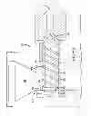
FIG. 2 is a top view of a feed box and feed roll.
FIGS. 3-6 illustrate alternate embodiments of the notch for the extruder screw.
DETAILED DESCRIPTION OF THE INVENTION
FIG. 1 illustrates an extruder flow head assembly 10 which includes an extruder screw 12 connected to a flow head 14 with a flow channel 16 leading to a die (not shown). The screw together with the die may be used to form a rubber component of visco-elastic material, such as rubber.
The extruder 12 has a screw 18 that is rotatable in a cylindrical barrel 20. The cylindrical barrel has an internal channel for housing the screw. The screw has an elongate cylindrical body 13 having at least two helical screw flights 30,32 mounted thereon. The screw is typically rotated by power means such as a motor and gearbox (not shown). The screw has a first discharge end forming a nose 19 and a second terminal end 21, typically having shallow flights 25 for keeping compound out of the splined screw-to-gearbox interface (not shown). The barrel 20 has a feed opening 22 at an entrance end 24 of the extruder. The feed opening is connected to a feed hopper 23. FIG. 2 illustrates the feed box at the entrance end of the extruder. The feed box has a screw, with the start of a screw flight 26. The screw depicted is a screw with a notch 30 machined into the screw in the area where the screw flight starts, 26. The action of the screw flight against the feed roll 29, tends to cut the rubber slab feed going into the feedbox. By machining a notch 30,40,46,50,60 (or channel) into this area of the screw (40 on FIG. 3) the screw flight is discontinuous and the scissors action of the screw flight against the feed roll will not cut off the compound slab feeding into the feedbox. The feedbox 23, typically exhibits a rolling ball 28 of compound, which indicates that the screw is properly fed (absence indicates underfeeding). It is important that the rubber slab being fed into the feedbox does not interfere with the rolling ball of compound, or the action of the rolling ball and the slab can also cause a slab bite-off. By directing the slab feed towards the rear of the feedbox and towards the screw notch or feed channel, interference with the rolling ball is avoided and the notch is allowed to provide a positive feeding assist. The use of a screw with a notch and a feed hopper with a guide keeping the slab from the rolling compound ball, greatly improves the occurrence of slab misfeeds, which are most prevalent with compounds having low “green strength”.
The rear end 21 of the extruder screw has been modified as shown in FIGS. 3-6. At the rear end 21 of the extruder end located where the helical flights are initiated, a notch 40 has been inserted in the screw flight at the terminal end near the feed box. As shown in FIG. 3, the notch 40 is circumferentially continuous, ie, it extends completely around the circumference of the screw. The notch cuts across the terminal ends 42 of the helical flights 30,32. The notch as shown in FIG. 3, is nonsymmetrical in shape. FIG. 4 illustrates a symmetrical, U shaped notch 46. FIG. 5 illustrates another asymmetrical notch 50 having a shallow depth. FIG. 6 illustrates a deep notch having a circular, symmetrical shape 60. The notch width of any of the above described notches may range from about 8 to about 40 mm depending upon the screw size, (increasing notch width with increasing screw diameter). The notch depth is preferably about ⅓ to about ⅔ of the channel width.
Experiments were conducted with a notched extruder screw over a range of speeds. It was observed that the notch reduced the number of misfeeds. It was also observed that directing the rubber into the feedbox area occupied by the rolling ball of compound could still cause a misfeed, but the action of the screw notch had the unexpected result that the feed was able to restart itself without any intervention. Complete clean-out of the extruder feedbox is typically required to re-establish normal compound feeding, with traditional extruder screws lacking the screw notch.
While certain representative embodiments have been shown for the purpose of illustrating the invention, it will be apparent to those skilled in the art that various changes and modifications can be made without departing from the scope of the invention.
Claims
What is claimed is:1. An extruder apparatus comprising:
A cylindrical barrel having a feed end and a discharge end, the feed end having an outlet in fluid communication with a feed box, an extruder screw mounted in the cylindrical barrel, said screw having an outer surface having one or more helical flights mounted thereon, said screw having a discharge end and a terminal end, said screw further comprising a notch.
2. The apparatus of claim 1 wherein the notch is circumferentially continuous.
3. The apparatus of claim 1 wherein the notch has a symmetrical cross-sectional shape.
4. The apparatus of claim 1 wherein the notch has an asymmetrical cross-sectional shape.
5. The apparatus of claim 1 wherein the notch has a width in the range of about 5 to 40 mm.
6. The apparatus of claim 1 wherein the notch is formed adjacent the screw flights.
7. The apparatus of claim 1 wherein the notch intersects at least one of the helical screw flights.
8. The apparatus of claim 1 wherein the notch has a symmetrical U cross-sectional shape.
9. The apparatus of claim 1 wherein the notch has a semicircular cross-sectional shape.
10. The apparatus of claim 1 wherein the notch is between the screw helical flights and the terminal end.
Images & Drawings included:


Sources:
- United States Patent and Trademark Office - verify current appl. status at the USPTO↗
Similar patent applications:
Recent applications in this class:
- » 20240326291 2024-10-03
DEVICE AND METHOD FOR PROCESSING PLASTIC MATERIAL - » 20240269895 2024-08-15
MATERIAL CONVEYING DEVICE - » 20230321873 2023-10-12
EXTRUDER AND MOLDING ASSEMBLY - » 20220355510 2022-11-10
EXTRUDER AND MOLDING ASSEMBLY - » 20220118652 2022-04-21
Powder storage apparatus, melt kneader, powder storage method, and production method for thermoplastic resin composition - » 20200307023 2020-10-01
Modular extruder - » 20200114543 2020-04-16
Plastic parts made from plastics having different melting points and a method of manufacturing same - » 20170225360 2017-08-10
Extruder screw with conveying portions and barrier portions and extrusion methods using the extruder screw and a plurality of barrel blocks - » 20170043502 2017-02-16
Kneading apparatus having plurality of segmented parts - » 20170008194 2017-01-12
Process and device for introducing additive materials in a receptacle at the area of highest pressure