Fuel cell plate and stack of cells comprising such a plate
US20140120449A1
2014-05-01
14/063,126
2013-10-25
✅ Patent granted
US 9,425,467 B2
2016-08-23
-
-
Basia Ridley | James Erwin
Christopher J. Cronin
2034-03-22
Abstract:
Fuel cell plate, the reactive face of the plate being provided with reliefs and hollows forming at least one circulation channel for a reagent, the at least one circulation channel for a reagent having an inlet communicating with a reagent distribution orifice formed through the plate, the plate also comprising a reagent inlet collector orifice that is distinct from the reagent distribution orifice, the reagent inlet collector orifice being provided to supply reagent to the inlet of at least one channel via a passage putting in fluid relationship the inlet collector orifice and the reagent distribution orifice, the inlet collector orifice extending longitudinally in the plane of the plate in a first longitudinal direction between a first bottom end and a second top end, the distribution orifice extending longitudinally in the plane of the plate in a second longitudinal direction between a first bottom end and a second top end, the first and second longitudinal directions being parallel to each other and vertical when the plate is in the vertical position of use, characterized in that, in the vertical position of use of the plate, the first bottom end of the inlet collector orifice is situated below the first bottom end of the distribution orifice.
Inventors:
- Julien MARTEAU 2 🇫🇷 Grenoble, France
- Arnaud CERCEAU 3 🇫🇷 Charavines, France
- Daniel Gastaldin 1 🇫🇷 Saint Nazaire Les Eymes, France
- Nicolas Jannin 5 🇫🇷 Sassenage, France
- Marion Paris 2 🇫🇷 Grenoble, France
- Elisabeth Rossinot 3 🇫🇷 Meaudre, France
- Helene Trouve 3 🇫🇷 Sassenage, France
Assignee:
- L'Air Liquide Societe Anonyme Pour L'Etude Et L'Exploitation Des Procedes Georges Claude 1,492 🇫🇷 Paris, France
- et l'Exploitation des Procedes Georges Claude 3 🇫🇷 Paris, France
- L'Air Liquide Société Anonyme Pour L'Étude 2 🇫🇷 Paris, France
Applicant:
Interested in similar patents?
Get notified when new applications in this technology area are published.
Classification:
H01M8/0258 » CPC main
Fuel cells; Manufacture thereof; Details; Collectors; Separators, e.g. bipolar separators; Interconnectors characterised by the configuration of channels, e.g. by the flow field of the reactant or coolant
H01M8/02 IPC
Fuel cells; Manufacture thereof Details
H01M8/04253 » CPC further
Fuel cells; Manufacture thereof; Auxiliary arrangements, e.g. for control of pressure or for circulation of fluids during start-up or shut-down; Depolarisation or activation, e.g. purging; Means for short-circuiting defective fuel cells Means for solving freezing problems
H01M8/24 IPC
Fuel cells; Manufacture thereof Grouping of fuel cells, e.g. stacking of fuel cells
H01M8/241 » CPC further
Fuel cells; Manufacture thereof; Grouping of fuel cells, e.g. stacking of fuel cells with solid or matrix-supported electrolytes
H01M8/0267 » CPC further
Fuel cells; Manufacture thereof; Details; Collectors; Separators, e.g. bipolar separators; Interconnectors having heating or cooling means, e.g. heaters or coolant flow channels
H01M8/04156 » CPC further
Fuel cells; Manufacture thereof; Auxiliary arrangements, e.g. for control of pressure or for circulation of fluids; Arrangements for control of reactant parameters, e.g. pressure or concentration of gaseous reactants with simultaneous supply or evacuation of electrolyte; Humidifying or dehumidifying with product water removal
H01M2008/1095 » CPC further
Fuel cells; Manufacture thereof; Fuel cells with solid electrolytes Fuel cells with polymeric electrolytes
Y02E60/50 » CPC further
Enabling technologies; Technologies with a potential or indirect contribution to GHG emissions mitigation; Hydrogen technology Fuel cells
Y02E60/50 » CPC further
Enabling technologies; Technologies with a potential or indirect contribution to GHG emissions mitigation; Hydrogen technology Fuel cells
H01M8/04 IPC
Fuel cells; Manufacture thereof Auxiliary arrangements, e.g. for control of pressure or for circulation of fluids
H01M8/10 IPC
Fuel cells; Manufacture thereof Fuel cells with solid electrolytes
H01M8/2485 » CPC further
Fuel cells; Manufacture thereof; Grouping of fuel cells, e.g. stacking of fuel cells; Details of groupings of fuel cells characterised by external manifolds Arrangements for sealing external manifolds; Arrangements for mounting external manifolds around a stack
Description
CROSS-REFERENCE TO RELATED APPLICATIONS
This application claims the benefit of priority under 35 U.S.C. §119 (a) and (b) to French patent application No. 1260189, filed Oct. 25, 2012, the entire contents of which are incorporated herein by reference.
BACKGROUND
1. Field of the Invention
The present invention concerns a fuel cell plate as well as a stack of cells comprising such a plate.
2. Related Art
A stack of elementary fuel cell cells is an assembly of a plurality of electrochemical cells. Conventionally, each cell consists of two plates (in particular bipolar), an Electrode Membrane Assembly, plate seals and a system for the arrival and exit of the fluids in the cell.
According to a known configuration, the cells and therefore the plates are oriented vertically, that is to say the plane of the plates is vertical. In the known architectures, depending on the conditions of use of the cells, problems may occur with regard to the management of the water in the fuel cell (for example an Electrode Membrane Assembly immersed in water, a surplus of water in the reactive channels, poor supply of air, etc.).
SUMMARY OF THE INVENTION
One aim of the present invention is to overcome all or some of the drawbacks of the prior art disclosed above.
The invention concerns more particularly a fuel cell plate of the proton exchange membrane type, the plate being intended to cooperate with another cell plate in order to sandwich an Electrode Membrane Assembly, in the position of use the plate is disposed in a vertical plane, the plate comprising two opposite faces, respectively a reactive face and a cooling face, the reactive face of the plate being provided with reliefs and hollows forming at least one circulation channel for a reagent, the at least one circulation channel for a reagent having an inlet communicating with a reagent distribution orifice formed through the plate, the plate also comprising a reagent inlet collector orifice that is distinct from the reagent distribution orifice, the reagent inlet collector orifice being provided to supply reagent to the inlet of at least one channel via a passage putting in fluid relationship the inlet collector orifice and the reagent distribution orifice, the inlet collector orifice extending longitudinally in the plane of the plate in a first longitudinal direction between a first bottom end and a second top end, the distribution orifice extending longitudinally in the plane of the plate in a second longitudinal direction between a first bottom end and a second top end, the first and second longitudinal directions being parallel to each other and vertical when the plate is in the vertical position of use. The invention is essentially characterised in that, in the vertical position of use of the plate, the first bottom end of the inlet collector orifice is situated below the first bottom end of the distribution orifice.
Moreover, embodiments of the invention may comprise one or more of the following features:
-
- in the vertical position of use of the plate, the first bottom end of the inlet collector orifice is situated below the first bottom end of the distribution orifice at a distance D of between 0.5 mm and 50 mm,
- the inlet collector orifice and the distribution orifice are adjacent and have parallel oblong shapes overall,
- the plate comprises a peripheral seal disposed on the reactive face and comprising a portion forming a loop around the inlet collector orifice,
- the at least one circulation channel comprises an outlet with a reagent discharge orifice formed through the plate, the plate also comprising a reagent outlet collector orifice that is distinct from the discharge orifice, the outlet collector orifice being provided to recover the reagent at the discharge from at least one channel via a passage putting in fluid relationship the outlet collector orifice and the discharge orifice, the outlet collector orifice extending longitudinally in a third direction in the plane of the plate between a first bottom end and a second top end, the discharge orifice extending longitudinally in the plane of the plate in a fourth longitudinal direction between a first bottom end and a second top end, the third and fourth longitudinal directions being parallel to each other and vertical when the plate is in the vertical position of use, and in that, in the vertical position of use of the plate, the first bottom end of the outlet collector orifice is situated below the first bottom end of the discharge orifice,
- in the vertical position of use of the plate, a portion of between one third and two thirds of the outlet collector orifice is situated below the discharge orifice.
The invention may also concern a stack of fuel cell cells in which the cells are provided with plates according to any one of the above or following features.
The invention may also concern any alternative device or method comprising any combination of the above or following features.
BRIEF DESCRIPTION OF THE FIGURES
Other particularities and advantages will emerge from a reading of the following description, given with reference to the figures, in which:
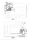
FIG. 1 shows a front view, schematic and partial, of the reactive face of a fuel cell plate illustrating a first detail of a possible example of an embodiment of the invention,
FIG. 2 shows a front view, schematic and partial, of the reactive face of a fuel cell plate illustrating a second detail of a possible example embodiment of the invention,
FIG. 3 shows a schematic and partial perspective view illustrating a stack of plates forming cells of a fuel cell.
DETAILED DESCRIPTION OF THE INVENTION
As illustrated in FIG. 1, the fuel cell plate comprises two opposite faces, respectively a reactive face and a cooling face.
FIG. 1 shows schematically and partially the reactive face that is provided with reliefs and hollows forming at least one circulation channel 2 for a reagent.
The at least one circulation channel 2 for a reagent has an inlet communicating with a reagent distribution orifice 12 formed through the plate 1. The plate 1 also comprises a reagent inlet collector orifice 3 that is distinct from the reagent distribution orifice 12. The reagent inlet collector orifice 3 is provided to supply reagent to the inlet of at least one channel 2 via a passage formed on the cooling face of the plate 1 putting in fluid relationship the inlet collector orifice 3 and the reagent distribution orifice 12. This passage is shown schematically by broken lines and may be formed by a hollow formed in the thickness of the plate at the separation between the two orifices 3, 12.
The inlet collector orifice 3 extends longitudinally in the plane of the plate 1 in a first longitudinal direction 13 between a first bottom end 31 and a second top end 30. The distribution orifice 12 extends longitudinally in the plane of the plate 1 in a second longitudinal direction 22 between a first bottom end 21 and a second top end 20. The first 13 and second 22 longitudinal directions are parallel to each other and vertical when the plate 1 is in the vertical position of use (cf. FIG. 3). In the vertical position of use of the plate, the first bottom end 31 of the inlet collector orifice 3 is situated below the first bottom end 21 of the distribution orifice 12.
As can be seen in FIG. 1, in the vertical position of use, the collector orifice 3 for entry of the reactive gases is mainly positioned above the distribution orifice 12, except for its bottom end 31.
In this way, there cannot be any significant reserve of water in the collectors 3 and distribution orifice 12 of a fuel cell stack. This avoids any problem of water management in the fuel cell, in particular during start-ups, changes in regime or purges (water hammer).
This downward withdrawal of the collector 3 with respect to the distribution orifice 12 also has an advantage for start-ups of the fuel cell at negative temperature. This is because, after prolonged storage at low temperature or at negative temperature, the condensation water will potentially stagnate or freeze at a low point on the collector 3 without obstructing the arrival of the gases at the distribution orifice 12 situated higher up.
FIG. 2 illustrates the arrangement of the outlet collector 6 with respect to the discharge orifice that receives the reactive gas discharged from the channel 2.
The arrangement of the outlet collector 6 with respect to the discharge orifice 5 is preferably symmetrically identical to the above with respect to the centre of the plate 1 (bottom end of the collector orifice 6 situated below the bottom end of the discharge orifice 5). That is to say the arrangements of the discharge orifices 5 and of the outlet collector 6 are systematically identical respectively to the distribution orifices 12 and inlet collectors 3. That is to say that the collectors 5, 6 are identical and disposed symmetrically with respect to the centre of the plate 1. Likewise, the distribution 12 and discharge 5 orifices are identical and disposed symmetrically with respect to the centre of the plate 1. The plate is thus symmetrical at its inlets and outlets. That is to say the plate does not have distinct high and low sides and can be mounted without requiring positive location to dispose the inlet at the top and the outlet at the bottom or vice versa. This facilitates the assembly of the fuel cell.
In addition, the symmetry (same dimensions) of the collectors 3, 6 and orifices 12, 5 between the inlet and outlet confers on the plate a good compromise in functioning between firstly the need to limit the size of the outlet orifices and collectors (to force the flow speed) and secondly the need to increase this size (to discharge large quantities of water) and the need to have an inlet (collector 3, orifice 12) of sufficient size.
The functioning of the fuel cell is improved in particular with regard to the discharges of water.
The discharge orifice 5 is for example mainly positioned above the outlet collector 6. This also prevents an accumulation of water in the gas channels and prevents “water returns” from the outlet collector 6 to the discharge orifice 5.
These structures thus allow better management of the water at the fluid inlet and outlets (collectors 3, 6, orifices 12, 5), in particular at low temperatures.
This improves the performance and service life of the corresponding cell, stack of cells and fuel cell.
It will be understood that many additional changes in the details, materials, steps and arrangement of parts, which have been herein described in order to explain the nature of the invention, may be made by those skilled in the art within the principle and scope of the invention as expressed in the appended claims. Thus, the present invention is not intended to be limited to the specific embodiments in the examples given above.
Claims
What is claimed is:1. A proton exchange membrane fuel cell plate, the plate being intended to cooperate with another proton exchange membrane fuel cell plate in order to sandwich an Electrode Membrane Assembly, the plate comprising opposed reactive and cooling faces, a reagent inlet collector orifice, and a reagent outlet collector orifice, in the position of use the plate being disposed in a vertical plane, wherein:
the reactive face of the plate is provided with reliefs and hollows forming at least one circulation channel for a reagent;
the at least one circulation channel for a reagent has an inlet communicating with a reagent distribution orifice formed through the plate;
the reagent distribution orifice is distinct from the reagent inlet collector orifice;
the reagent inlet collector orifice is provided to supply reagent to the inlet of at least one channel via a passage putting in fluid relationship the inlet collector orifice and the reagent distribution orifice;
the inlet collector orifice extends longitudinally in the plane of the plate in a first longitudinal direction between a first bottom end and a second top end;
the distribution orifice extends longitudinally in the plane of the plate in a second longitudinal direction between a first bottom end and a second top end;
the first and second longitudinal directions are parallel to each other and vertical when the plate is in the vertical position of use;
in the vertical position of use of the plate, the first bottom end of the inlet collector orifice is situated below the first bottom end of the distribution orifice;
the at least one circulation channel comprises an outlet with a reagent discharge orifice formed through the plate;
the reagent outlet collector orifice is distinct from the discharge orifice;
the outlet collector orifice is designed to recover the reagent at the discharge from at least one channel via a passage putting in fluid relationship the outlet collector orifice and the outlet orifice;
the outlet collector orifice extends longitudinally in a third direction in the plane of the plate between a first bottom end and a second top end;
the discharge orifice extends longitudinally in the plane of the plate in a fourth longitudinal direction between a first bottom end and a second top end;
the third and fourth longitudinal directions are parallel to each other and vertical when the plate is in the vertical position of use;
in the vertical position of use of the plate, the first bottom end of the outlet collector orifice is situated below the first bottom end of the discharge orifice;
the arrangements of the outlet collectors and of the discharge orifice are symmetrically identical respectively to the inlet collector and to the distribution orifice with respect to the centre of the plate.
2. The plate of claim 1, wherein, in the vertical position of use of the plate, the first bottom end of the inlet collector orifice is situated below the first bottom end of the distribution orifice at a distance D of between 0.5 mm and 50 mm.
3. The plate of claim 1, wherein the inlet collector orifice and the distribution orifice are adjacent and have parallel oblong shapes overall.
4. The plate of claim 1, wherein the plate comprises a peripheral seal disposed on the reactive face that comprises a portion forming a loop around the inlet collector orifice.
5. The plate of claim 1, wherein, in the vertical position of use of the plate, a proportion lying between one third and two thirds of the outlet collector orifice is situated below the discharge orifice.
6. A stack of fuel cells comprising the proton exchange membrane fuel Cell plates of claim 1 sandwiching Electrode Membrane Assembly plates.
Images & Drawings included:


Sources:
- United States Patent and Trademark Office - verify current appl. status at the USPTO↗
Similar patent applications:
- » 20230163322
BIPOLAR PLATE ASSEMBLY, USE OF A BIPOLAR PLATE ASSEMBLY, AND ELECTROLYSIS OR FUEL CELL STACK COMPRISING A PLURALITY OF BIPOLAR PLATE ASSEMBLIES - » 20180248204
Bipolar plate and a fuel cell stack comprising same - » 20140356747
Spliced bipolar plates for fuel cells and fuel cell stacks comprising the same - » 20220246949
Fuel cell stack comprising variable bipolar plates - » 20090214930
Sealing joint and fuel cell plate, cells obtained and resulting fuel cells comprising a stack of such cells - » 20180175406
Separation plate, manufacturing method therefor, and fuel cell stack comprising same - » 20180145346
Separating plate, method for manufacturing same, and fuel cell stack comprising same - » 20130302712
FUEL-CELL STACK COMPRISING A STACK OF CELLS AND BIPOLAR CONDUCTIVE PLATES - » 20230178759
PLATE DEVICE FOR A FUEL STACK AND FUEL CELL DEVICE COMPRISING THE SAME - » 20230187660
PLATE DEVICE FOR A FUEL STACK AND FUEL CELL DEVICE COMPRISING THE SAME
Recent applications in this class:
- » 20250293273 2025-09-18
BIPOLAR PLATE BULK MOLDING COMPOUND MATERIAL CHOICE - » 20250286084 2025-09-11
Fuel Cell Integrated System - » 20250279440 2025-09-04
CURRENT COLLECTOR AND ELECTROCHEMICAL CELL STACK - » 20250266469 2025-08-21
THERMAL MANAGEMENT OF A FUEL CELL ASSEMBLY - » 20250260024 2025-08-14
REDOX FLOW BATTERY INCLUDING STACKED FRAMES AND METHOD FOR MANUFACTURING THE SAME - » 20250246643 2025-07-31
SEPARATOR PLATE FOR AN ELECTROCHEMICAL SYSTEM - » 20250233169 2025-07-17
FUEL CELL STACK - » 20250201868 2025-06-19
CELL STACK OF FUEL CELL - » 20250183329 2025-06-05
SEPARATOR FOR FUEL CELL AND UNIT CELL FOR FUEL CELL INCLUDING THE SAME - » 20250167258 2025-05-22
BIPOLAR PLATE FOR AN ELECTROCHEMICAL SYSTEM
Recent applications for this Assignee:
- » 20250290202 2025-09-18
FLUORINATION OF ANCILLARY LIGANDS OF GROUP (III) PRECURSORS AND THEIR APPLICATIONS IN VAPOR DEPOSITIONS - » 20250283579 2025-09-11
DEVICE FOR STORING AND SUPPLYING CRYOGENIC FLUID, IN PARTICULAR LIQUEFIED HYDROGEN - » 20250256958 2025-08-14
METHOD AND SYSTEM FOR HEATING A REFORMER WITH AN AMMONIA-FIRED BURNER PRODUCING A STABLE FLAME - » 20250229214 2025-07-17
PROCESS AND APPARATUS FOR CAPTURE OF CO2 - » 20250223704 2025-07-10
SPIN-COATABLE METAL DOPED SILICON-CONTAINING FILM-FORMING COMPOSITIONS AND PROCESSES OF USING THEM FOR DEPOSITION - » 20250223696 2025-07-10
GROUP 2 METAL CONTAINING FILM FORMING COMPOSITIONS AND VAPOR DEPOSITION OF THE FILMS USING THE SAME - » 20250189184 2025-06-12
FLUID CIRCULATION DEVICE, INSTALLATION AND METHOD USING SUCH A DEVICE - » 20250184007 2025-06-05
MODULATION SYSTEM CONFIGURED TO CONTROL MODULATION OF A SIGNAL - » 20250179938 2025-06-05
COUPLED ASSEMBLY - » 20250166974 2025-05-22
SULFUR-CONTAINING MOLECULES FOR HIGH ASPECT RATIO PLASMA ETCHING PROCESSES