Rugged furcation tube
US20140140669A1
2014-05-22
13/832,131
2013-03-15
✅ Patent granted
US 9,536,640 B2
2017-01-03
-
-
Sung Pak
Myers Bigel, P.A.
2034-09-19
Abstract:
A furcation tube for optical fibers has a polymer inner jacket surrounded by a fiber and strength member layer of fibers and strength rods, which is surrounded by a polymer outer jacket. The inner jacket may surround a plurality of inner tubes. The strength members may be arrayed around the inner jacket generally equidistant from one another. The strength members may be resin pultruded fiber rods and the fiber may be para-aramid fibers.
Assignee:
- ANDREW LLC 404 🇺🇸 Hickory, NC, United States
- CommScope Technologies LLC 2,676 🇺🇸 Hickory, NC, United States
Applicant:
Interested in similar patents?
Get notified when new applications in this technology area are published.
Classification:
G02B6/4401 » CPC main
Light guides; Mechanical structures for providing tensile strength and external protection for fibres, e.g. optical transmission cables Optical cables
G02B6/44 IPC
Light guides Mechanical structures for providing tensile strength and external protection for fibres, e.g. optical transmission cables
G02B6/4416 » CPC further
Light guides; Mechanical structures for providing tensile strength and external protection for fibres, e.g. optical transmission cables; Optical cables; Cables for special applications Heterogeneous cables
G02B6/4472 » CPC further
Light guides; Mechanical structures for providing tensile strength and external protection for fibres, e.g. optical transmission cables; Optical cables; Auxiliary devices terminating, fan-out, clamping, strain-relieving or like devices Manifolds
Y10T29/49117 » CPC further
Metal working; Method of mechanical manufacture; Electrical device making Conductor or circuit manufacturing
H01B11/22 » CPC further
Communication cables or conductors Cables including at least one electrical conductor together with optical fibres
G02B6/4471 » CPC further
Light guides; Mechanical structures for providing tensile strength and external protection for fibres, e.g. optical transmission cables; Optical cables; Auxiliary devices terminating, fan-out, clamping, strain-relieving or like devices
H02G1/08 IPC
Methods or apparatus specially adapted for installing, maintaining, repairing or dismantling electric cables or lines for laying cables, e.g. laying apparatus on vehicle through tubing or conduit, e.g. rod or draw wire for pushing or pulling
H02G1/081 » CPC further
Methods or apparatus specially adapted for installing, maintaining, repairing or dismantling electric cables or lines for laying cables, e.g. laying apparatus on vehicle through tubing or conduit, e.g. rod or draw wire for pushing or pulling using pulling means at cable ends, e.g. pulling eyes or anchors
Y10T29/49826 » CPC further
Metal working; Method of mechanical manufacture Assembling or joining
H01B13/00 » CPC main
Apparatus or processes specially adapted for manufacturing conductors or cables
H02G15/013 » CPC further
Cable fittings Sealing means for cable inlets
Description
BACKGROUND
1. Field of the Invention
This invention relates to optical cable assemblies. More particularly, the invention relates to an optical fiber furcation tube with improved strength characteristics and/or ease of use.
2. Description of Related Art
The wireless communications industry is changing from traditional signal delivery from ground based transceivers delivering/receiving the RF signal to/from the antenna atop the radio tower via bulky/heavy/high material cost metal RF coaxial cable to optical signal delivery to a tower top mounted transceiver known as a remote radio unit (RRU) or remote radio head (RRH) with implementation of fiber to the antenna (FTTA) cabling.
Optical conductors of FTTA cabling may be fragile, requiring great care to properly terminate.
Prior RRU/RRH terminations have employed an over-voltage protection and/or distribution box for terminating each of the optical conductors as individual jumpers. These additional enclosures require field termination of the several conductors atop the radio tower, increasing installation time and labor requirements. Further, each break in the conductors provides another opportunity for signal degradation and/or environmental fouling.
Factory terminated cable assemblies are known. However, these assemblies may apply splices to the conductors, require a relatively large in-line break-out/splice enclosure and/or utilize environmental seals which fail to positively interlock the jumpers therewith, which may increase the potential for cable and/or individual conductor damage to occur.
Furcation tubes may be applied to fibers and or fiber bundles stripped back from the cable end to protect the optical fibers from damage between the cable and the optical fiber termination. Prior optical fiber furcation tubes typically consist of an inner polymer tube surrounded by a para-aramid synthetic fiber sheath, or a para-aramid synthetic fiber sheath alone. Further, it may be labor intensive to prepare the furcation tube for interconnection and/or to thread an optical fiber through a furcation tube.
Therefore, an object of the invention is to provide an optical conductor furcation tube solution that overcomes deficiencies in the prior art.
BRIEF DESCRIPTION OF THE DRAWINGS
The accompanying drawings, which are incorporated in and constitute a part of this specification, illustrate embodiments of the invention, where like reference numbers in the drawing figures refer to the same feature or element and may not be described in detail for every drawing figure in which they appear and, together with a general description of the invention given above, and the detailed description of the embodiments given below, serve to explain the principles of the invention.
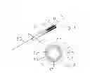
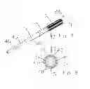
FIG. 1 is a schematic isometric view of an exemplary furcation tube with a pull strand.
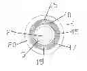
FIG. 2 is a schematic end view of the furcation tube of FIG. 1.
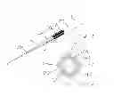
FIG. 3 is a schematic isometric view of the furcation tube of FIG. 1, with an optical fiber inserted.
FIG. 4 is a schematic end view of the furcation tube of FIG. 3.
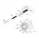
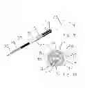
FIG. 5 is a schematic isometric view of an alternative furcation tube with an optical fiber inserted.
FIG. 6 is a schematic end view of the furcation tube of FIG. 5.
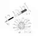
FIG. 7 is a schematic isometric view of an alternative furcation tube with multiple inner tubes.
FIG. 8 is a schematic end view of the furcation tube of FIG. 7.
FIG. 9 is a schematic isometric view of an alternative furcation tube with multiple inner tubes and a foam layer.
FIG. 10 is a schematic end view of the furcation tube of FIG. 9.
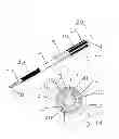
FIG. 11 is a schematic isometric view of an alternative furcation tube with multiple inner tubes, a foam layer and pull strands.
FIG. 12 is a schematic end view of the furcation tube of FIG. 11.
FIG. 13 is a schematic isometric view of the furcaction tube of FIG. 11, with optical fibers inserted.
FIG. 14 is a schematic end view of the furcation tube of FIG. 13.
DETAILED DESCRIPTION
In order to connect conductors and/or fibers of a cable directly to the RRH, optical fiber and electrical conductors, if present, may be separated from the cable as individual jumpers, the jumpers protected with separate furcation tubes. The inventor has recognized that, although available optical furcation tubes may provide protection, compared to a bare optical fiber, damage to optical fibers may still occur if the furcation tube is crushed, kinked or bent.
An exemplary rugged furcation tube 1 has an inner jacket 5 surrounded by a radial array of fibers 10 and strength members 15 provided in a fiber and strength layer 17 which are surrounded by an outer jacket 20, for example as shown in FIGS. 1 and 2.
The fiber and strength layer 17 may be provided with a radial array of the strength members 13 spaced generally equal distances apart from one another, such that one of the strength members 13 is provided between each of the bundles of fiber 10.
The inner jacket 5 may be dimensioned for ease of inserting an optical fiber 30, fiber bundle and/or electrical conductor therethrough, with or without the assistance of a pull strand 25, for example, as shown in FIGS. 3 and 4. The pull strand 25 may be provided with suitable strength for pulling the desired conductors through the inner jacket 5, such as a para-aramid synthetic fiber or yarn.
The inner jacket 5 may be provided, for example, as a polymer material with desired strength, cost, temperature and/or moisture resistance characteristics, such as polyethylene, thermoplastic polyester elastomer, polytetrafluoroethylene, nylon, polyvinylidene difluoride and the like.
The inner jacket 5 may alternatively be provided further surrounding a fiber layer 35 and an inner tube 40, for example as shown in FIGS. 5 and 6.
Alternatively, the inner jacket 5 may surround a plurality of inner tubes 40, for example two inner tubes 40, as shown in FIGS. 9 and 10, or four inner tubes 40, as shown in FIGS. 7 and 8. The inner tubes 40 may be provided in a range of colors, for example for ease of fiber identification and termination with a 4 fiber-ODC connector or the like.
A pull strand 25 may also be provided in the inner diameter of each inner tube 40.
A fiber layer 35 may also be applied to fill space between and/or further stabilize the plurality of inner tubes 40 and the inner jacket 5, for example as shown in FIGS. 9-14.
The strength members 15 may be para-aramid, glass-reinforced plastic or other forms of resin-pultruded fiber rod selected for a desired tensile strength and cable bend radius. Alternatively, the strength members may be embedded in the outer jacket 20. One skilled in the art will appreciate that the strength members 15 also provide a thermal expansion stability characteristic to the furcation tube 1.
Diameters of the outer jacket 20 and/or inner jacket 5 may be selected to seat within connectors or seal glands at cable entry points of intended equipment and/or junction boxes.
One or more rip cords 45 may be provided between the outer and inner jackets 20, 5, for ease of stripping back the fiber and strength layer 17 during cable termination.
The fibers of the fiber and strength layer 17 and/or fiber layer 35 may be, for example, para-aramid fibers or yarn bundles.
One skilled in the art will appreciate that the rugged furcation tube 1 enables the splice-free fiber distribution of an optical cable, wherein the optical fibers are protected from kinking, crushing and/or thermal stresses. Further, color coding of inner tubes 40, pull strands 25 and/or rip cords 45 may simplify installation of the furcation tube 1.
| Table of Parts |
| 1 | furcation tube |
| 5 | inner jacket |
| 10 | fiber |
| 15 | strength member |
| 17 | fiber and strength layer |
| 20 | outer jacket |
| 25 | pull strand |
| 30 | optical fiber |
| 35 | fiber layer |
| 40 | inner tube |
| 45 | rip cord |
Where in the foregoing description reference has been made to materials, ratios, integers or components having known equivalents then such equivalents are herein incorporated as if individually set forth.
While the present invention has been illustrated by the description of the embodiments thereof, and while the embodiments have been described in considerable detail, it is not the intention of the applicant to restrict or in any way limit the scope of the appended claims to such detail. Additional advantages and modifications will readily appear to those skilled in the art. Therefore, the invention in its broader aspects is not limited to the specific details, representative apparatus, methods, and illustrative examples shown and described. Accordingly, departures may be made from such details without departure from the spirit or scope of applicant's general inventive concept. Further, it is to be appreciated that improvements and/or modifications may be made thereto without departing from the scope or spirit of the present invention as defined by the following claims.
Claims
1. A furcation tube for optical fibers, comprising:
a polymer inner jacket;
the inner jacket surrounded by a fiber and strength layer of fibers and strength members; and
a polymer outer jacket surrounding the fiber and strength layer.
2. The furcation tube of claim 1, wherein the inner jacket surrounds a plurality of inner tubes.
3. The furcation tube of claim 2, wherein the inner tubes are each a different color.
4. The furcation tube of claim 2, further including a fiber layer in a fill space between the inner tubes and the inner jacket.
5. The furcation tube of claim 1, further including a rip cord between the inner jacket and the outer jacket.
6. The furcation tube of claim 1, further including a pull string in the inner jacket.
7. The furcation tube of claim 2, further including a pull string in each of the inner tubes.
8. The furcation tube of claim 1, wherein the strength members are distributed in a radial array around the inner jacket, generally equidistant from one another.
9. The furcation tube of claim 1, wherein the fiber and strength layer is provided with strength members and fiber bundles; one of the strength members provided between each of the fiber bundles.
10. The furcation tube of claim 1, wherein the fibers are para-aramid fibers.
11. The furcation tube of claim 1, further including a plurality of glass-reinforced plastic rods in the fiber and strength layer.
12. The furcation tube of claim 1, further including a plurality of resin pultruded fiber rods in the fiber and strength layer.
13. The furcation tube of claim 1, wherein the fiber and strength layer includes para-aramid fibers.
14. The furcation tube of claim 1, wherein the inner jacket and the outer jacket are aligned coaxially.
15. A method for manufacturing a furcation tube, comprising:
providing a polymer inner jacket;
surrounding the inner jacket with a fiber and strength layer of fibers and strength members; and
surrounding the fiber and strength layer with a polymer jacket
16. The method of claim 15, further including the step of surrounding a plurality of inner tubes with the inner jacket.
17. The method of claim 16, wherein the inner tubes are each a different color.
18. The method of claim 16, further including a fiber layer in a fill space between the inner tubes and the inner jacket.
19. The method of claim 15, further including the step of inserting a rip cord between the inner jacket and the outer jacket.
20. The method of claim 15, further including the step of placing a pull string in the inner jacket.
Images & Drawings included:
Sources:
- United States Patent and Trademark Office - verify current appl. status at the USPTO↗
Recent applications in this class:
- » 20230141383 2023-05-11
HOUSING STRUCTURE, PULLING-END-EQUIPPED OPTICAL CABLE, AND METHOD FOR MANUFACTURING HOUSING STRUCTURE - » 20230064925 2023-03-02
Medical observation system and transmission cable - » 20210364719 2021-11-25
Flooding Composition with Polysiloxane - » 20210318504 2021-10-14
Utility pole localization using distributed acoustic sensing - » 20200174208 2020-06-04
Wired optical communication assembly having first and second arrayed waveguide gratings disposed substantially parallel with each other - » 20200116962 2020-04-16
Multiports having a connection port insert and methods of making the same - » 20190235189 2019-08-01
Wired optical communication assembly - » 20180188461 2018-07-05
Optical cable and optical cable assembly having the same - » 20150139593 2015-05-21
OPTICAL FIBER CABLE - » 20150083904 2015-03-26
Optical cable, downhole system having optical cable, and method thereof
Recent applications for this Assignee:
- » 20250284083 2025-09-11
TELECOMMUNICATIONS CABINET - » 20250284059 2025-09-11
SYSTEM FOR PROTECTING TELECOMMUNICATIONS CABLE SPLICE ARRANGEMENTS - » 20250271629 2025-08-28
TELECOMMUNICATIONS EQUIPMENT INCLUDING SLIDING FIBER ADAPTER MODULES - » 20250271623 2025-08-28
FIBER OPTIC CONNECTOR WITH SHUTTER - » 20250264683 2025-08-21
CABLE FIXATION DEVICES AND ARRANGEMENTS WITH IMPROVED INSTALLATION AND SPACE UTILIZATION AT TELECOMMUNICATIONS ENCLOSURES - » 20250264680 2025-08-21
RAPID UNIVERSAL RACK MOUNT ENCLOSURE - » 20250251562 2025-08-07
FIBER MANAGEMENT TRAY ARRANGEMENTS AND ASSEMBLIES FOR FIBER OPTIC CLOSURE ORGANIZERS - » 20250251561 2025-08-07
OPTICAL FIBER MANAGEMENT TRAY FOR ROLLABLE FIBER RIBBONS - » 20250237839 2025-07-24
FIBER OPTIC ENCLOSURE WITH EXTERNAL CABLE SPOOL - » 20250237836 2025-07-24
FIBER OPTIC CABLE SEALING DEVICE