Method of manufacturing a flexible portable electronic device
US20140166192A1
2014-06-19
14/107,126
2013-12-16
✅ Patent granted
US 9,205,598 B2
2015-12-08
-
-
William Bell
Oblon, McClelland, Maier & Neustadt, L.L.P.
2034-06-19
Abstract:
Method of mass producing a flexible portable electronic device capable of at least processing information, the method including the steps consisting in passing a first impermeable plastic strip through an overmoulding station in which the first impermeable plastic strip is overmoulded using a plastic material,
the method further including the steps consisting in passing a second impermeable plastic strip with a bottom surface facing upwards, in succession:
-
- through a printing station in which the second impermeable plastic strip receives, on the bottom surface thereof, at least one decorative ink;
- through an assembly station in which the second impermeable plastic strip receives, in various places on the bottom surface thereof, the electronic assemblies for processing information,
joining and welding the first overmoulded impermeable plastic strip to the second decorated impermeable plastic strip, and then in cutting out and releasing the portable electronic devices.
Assignee:
- The Swatch Group Research and Development Ltd. 683 🇨🇭 Marin, Switzerland
Applicant:
Interested in similar patents?
Get notified when new applications in this technology area are published.
Classification:
B29C65/74 » CPC main
Joining of preformed parts ; Apparatus therefor by welding and severing, or by joining and severing, the severing being performed in the area to be joined, next to the area to be joined, in the joint area or next to the joint area
B29C45/0053 » CPC further
Injection moulding, i.e. forcing the required volume of moulding material through a nozzle into a closed mould; Apparatus therefor combined with a final operation, e.g. shaping
B29C45/14016 » CPC further
Injection moulding, i.e. forcing the required volume of moulding material through a nozzle into a closed mould; Apparatus therefor incorporating preformed parts or layers, e.g. injection moulding around inserts or for coating articles; Inserting articles into the mould Intermittently feeding endless articles, e.g. transfer films, to the mould
B29C45/14024 » CPC further
Injection moulding, i.e. forcing the required volume of moulding material through a nozzle into a closed mould; Apparatus therefor incorporating preformed parts or layers, e.g. injection moulding around inserts or for coating articles; Inserting articles into the mould; Intermittently feeding endless articles, e.g. transfer films, to the mould and punching or cutting a portion from the endless articles during mould closing
B29C65/1654 » CPC further
Joining of preformed parts ; Apparatus therefor by heating, with or without pressure using wave energy or particle radiation; Laser beams characterised by the way of heating the interface scanning at least one of the parts to be joined
B29C66/83411 » CPC further
General aspects of processes or apparatus for joining preformed parts; General aspects of machine operations or constructions and parts thereof characterised by the movement of the joining or pressing tools moving with the parts to be joined; Roller, cylinder or drum types; Band or belt types; Ball types Roller, cylinder or drum types
B29C65/1635 » CPC further
Joining of preformed parts ; Apparatus therefor by heating, with or without pressure using wave energy or particle radiation; Laser beams characterised by the way of heating the interface at least passing through one of the parts to be joined, i.e. laser transmission welding
B29C65/1683 » CPC further
Joining of preformed parts ; Apparatus therefor by heating, with or without pressure using wave energy or particle radiation; Laser beams making use of an absorber or impact modifier coated on the article
B29C66/0346 » CPC further
General aspects of processes or apparatus for joining preformed parts; General aspects dealing with the joint area or with the area to be joined; After-treatments in the joint area; Thermal after-treatments Cutting or perforating, e.g. burning away by using a laser or using hot air
B29C66/1122 » CPC further
General aspects of processes or apparatus for joining preformed parts; General aspects dealing with the joint area or with the area to be joined; Particular design of joint configurations particular design of the joint cross-sections; Joint cross-sections comprising a single joint-segment, i.e. one of the parts to be joined comprising a single joint-segment in the joint cross-section; Single lapped joints Single lap to lap joints, i.e. overlap joints
B29C66/433 » CPC further
General aspects of processes or apparatus for joining preformed parts; General aspects of joining substantially flat articles, e.g. plates, sheets or web-like materials; Making flat seams in tubular or hollow articles; Joining single elements to substantially flat surfaces; Joining substantially flat articles ; Making flat seams in tubular or hollow articles; Joining a relatively small portion of the surface of said articles Casing-in, i.e. enclosing an element between two sheets by an outlined seam
B29C2045/0079 » CPC further
Injection moulding, i.e. forcing the required volume of moulding material through a nozzle into a closed mould; Apparatus therefor combined with a final operation, e.g. shaping applying a coating or covering
B29C2791/001 » CPC further
Shaping characteristics in general Shaping in several steps
B29C2793/009 » CPC further
Shaping techniques involving a cutting or machining operation after shaping
B29L2031/3481 » CPC further
Other particular articles; Electrical apparatus, e.g. sparking plugs or parts thereof Housings or casings incorporating or embedding electric or electronic elements
G04G17/08 » CPC further
Structural details; Housings Housings
G04G17/083 » CPC further
Structural details; Housings; Housings Watches distributed over several housings
B29C45/14 IPC
Injection moulding, i.e. forcing the required volume of moulding material through a nozzle into a closed mould; Apparatus therefor incorporating preformed parts or layers, e.g. injection moulding around inserts or for coating articles
B29C43/26 » CPC further
Compression moulding, i.e. applying external pressure to flow the moulding material; Apparatus therefor of articles of indefinite length in several steps
B29C43/28 » CPC further
Compression moulding, i.e. applying external pressure to flow the moulding material; Apparatus therefor of articles of indefinite length incorporating preformed parts or layers, e.g. compression moulding around inserts or for coating articles
B29C45/00 IPC
Injection moulding, i.e. forcing the required volume of moulding material through a nozzle into a closed mould; Apparatus therefor
B29C69/02 » CPC further
Combinations of shaping techniques not provided for in a single one of main groups - , e.g. associations of moulding and joining techniques; Apparatus therefore of moulding techniques only
B29C43/14 » CPC further
Compression moulding, i.e. applying external pressure to flow the moulding material; Apparatus therefor of articles of definite length, i.e. discrete articles in several steps
B29C43/18 » CPC further
Compression moulding, i.e. applying external pressure to flow the moulding material; Apparatus therefor of articles of definite length, i.e. discrete articles incorporating preformed parts or layers, e.g. compression moulding around inserts or for coating articles
B29C65/16 » CPC further
Joining of preformed parts ; Apparatus therefor by heating, with or without pressure using wave energy or particle radiation Laser beams
B29C65/00 IPC
Joining of preformed parts ; Apparatus therefor
Description
This application claims priority from European Patent Application No. 12197482.8 filed 17 Dec. 2012, the entire disclosure of which is incorporated herein by reference.
FIELD OF THE INVENTION
The present invention concerns a method of manufacturing a flexible portable electronic device. More specifically, the present invention concerns a method of manufacturing this type of flexible portable electronic device in strips.
SUMMARY OF THE INVENTION
It is an object of the present invention to manufacture a flexible portable electronic device capable of at least elaborating or processing information, said portable electronic device including a flexible body, arranged to be capable of being secured to a part of a user's body, and an electronic assembly for processing information. The body of the portable electronic device is formed of a layer of plastic material such as an elastomer, which gives the portable electronic device thickness and mechanical resistance. This layer of plastic material is coated with a first impermeable plastic film, a second impermeable plastic film being secured to an external perimeter of the first impermeable plastic film. The electronic assembly for elaborating information is arranged between the first and second impermeable plastic films.
To make this type of flexible portable electronic device, a piece-by-piece manufacturing method consists in performing the following operations:
-
- overmoulding a layer of flexible plastic material, which forms the body of the portable electronic device, on an external face of a first impermeable plastic film;
- mounting the electronic assembly for processing information on the inner face side of the first impermeable plastic film, and
- securing a second impermeable plastic film onto the first impermeable plastic film, so as to delimit, between the first and second impermeable plastic films, an impermeable capsule or cavity which houses the electronic assembly for processing information.
Where necessary, the method may include an additional step which consists, before overmoulding the first impermeable plastic film, in thermoforming the first impermeable plastic film to give the first impermeable plastic film a desired contour.
This type of piece-by-piece manufacturing method is suitable for small scale manufacturing, typically for manufacturing prototypes for validating a design. It will be clear, however, that a piece-by-piece manufacturing method of this type cannot be envisaged for large scale manufacturing.
It is an object of the present invention to answer these requirements by providing a method of mass producing flexible portable electronic devices, said manufacturing method having, in particular, a large degree of freedom as to the choice of the shapes, thickness and decoration of the portable electronic devices.
The present invention therefore concerns a method of mass producing a flexible portable electronic device capable of at least processing information, the portable electronic device including an electronic assembly for processing information, the method including the steps consisting in passing a first impermeable plastic strip through an overmoulding station in which the first impermeable plastic strip is overmoulded using a flexible plastic material which will give the resulting flexible portable electronic devices thickness and mechanical resistance,
the method further including the steps consisting in passing a second impermeable plastic strip with a bottom surface facing upwards, in succession:
-
- through a printing station in which the bottom surface of the second impermeable plastic strip receives at least a decorative ink;
- through an assembling station in which the bottom surface of the second impermeable plastic strip receives, at various locations, the electronic assemblies for processing information.
Finally the method includes the step consisting in joining and securing the first overmoulded impermeable plastic strip with the second decorated impermeable plastic strip, then in cutting out and releasing the flexible portable electronic devices.
As a result of these features, the present invention provides a method of manufacturing in strips a flexible portable electronic device in which it is possible, by using the same, single manufacturing line, to develop the portable electronic devices with different shapes, thicknesses, flexible body materials and decorations. It is also possible to envisage adapting the models of portable electronic devices in real time, or online by the action of the buyer.
According to a complementary feature of the invention, the manufacturing method includes the step consisting, before the initial step of overmoulding the first impermeable plastic strip, in moving the first impermeable plastic strip through a thermoforming station to arrange a plurality of housings, each intended to subsequently receive at least one internal component of the flexible portable electronic device, at various locations in the first impermeable plastic strip.
BRIEF DESCRIPTION OF THE DRAWINGS
Other features and advantages of the present invention will appear more clearly from the following detailed description of an implementation of the manufacturing method according to the invention, this example being given purely by way of non-limiting illustration with reference to the annexed drawing, in which:
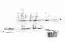
FIG. 1A is a diagram of the left part of a manufacturing plant for implementing the method of the invention; and
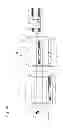
FIG. 1B is a diagram of the right part of a manufacturing plant for implementing the method of the invention, this Figure completing FIG. 1A.
DETAILED DESCRIPTION OF THE PREFERRED EMBODIMENTS
The present invention proceeds from the general inventive idea which consists in providing a method of manufacturing a flexible portable electronic device wherein a first part of the assembling operations is performed on a first flexible impermeable strip, while a second part of the assembling operations is performed on a second flexible impermeable strip, the first and second impermeable strips being assembled in a last manufacturing step, and then cut to release the individual portable electronic devices.
FIG. 1A is a diagram of the left part of a manufacturing plant for implementing the method of the invention, while FIG. 1B is a diagram of the right part of the manufacturing plant for implementing the method of the invention, the combination of FIGS. 1A and 1B illustrating the manufacturing plant as a whole. It will be noted that the left part of the manufacturing plant illustrated in FIG. 1A is connected to the right part of the manufacturing plant illustrated in FIG. 1B in an area marked with an arrow A in FIG. 1B.
Designated as a whole by the general reference numeral 1, the left part of the manufacturing plant for implementing the manufacturing method of the invention includes a thermoforming station 2 through which from left to right in the drawing there is made to pass a first impermeable plastic strip 4 to arrange in places in the first impermeable plastic strip 4 a plurality of housings 6 each intended to subsequently receive at least one internal component of flexible portable electronic device 8, such as an electronic assembly 10 for elaborating or processing information. This technique consists in hot pressing first impermeable plastic strip 4 in a first mould 10 comprising two pattern cavities 12 and 14 which have complementary shapes matching the contour required to be given to impermeable plastic strip 4. It will be noted that this operation is optional and depends only upon the sharpness of the shape to be replicated. Where necessary, this operation may be performed at the same time as the moulding operation described above.
After thermoforming immediately followed by cooling, first impermeable plastic strip 4 is overmoulded with a flexible plastic material, for example an elastomer, which will give the resulting portable electronic devices 8 a thickness and volume making said electronic devices 8 comfortable to wear. This technique is commonly known as film insert moulding. To that end, first impermeable plastic strip 4 is passed through an overmoulding station 16. This overmoulding station 16 includes a second mould 18 with a top part 20 identical to the pattern cavity 12 of the first mould 10 and a bottom part 22. Top part 20 of second mould 18, against which first impermeable plastic strip 4 is pressed, has a contour matching that of first impermeable plastic strip 4, and bottom part 22 has exclusion areas 24 at the places where the plastic material used to make bodies 26 of portable electronic devices 14 will be injected.
At the end of the manufacturing steps described above, there is formed in first impermeable plastic strip 4 a plurality of plastic bodies 26 which still form a single piece with impermeable plastic strip 4 and which have substantially the shape of a band or bracelet. The manufacturing method may be supplemented by a step of inserting bracelet fastening elements 28 such as magnets.
Designated as a whole by the general reference numeral 30, the right part of the plant for implementing the manufacturing method of the invention includes a heat transfer station 32 through which there passes, from right to left in the drawing, a second impermeable plastic strip 34, which receives, in places, on a bottom surface 36, a layer 38 of material able to absorb laser radiation.
Second impermeable plastic strip 34 then passes into a printing station 40 in which the second impermeable plastic strip 34 receives at least one decorative ink on bottom surface 36.
The second impermeable plastic strip 34 then also passes through a lamination station 42 in which an adhesive film 44 and a flexible display device 46, such as a liquid crystal display cell, are laminated in succession on bottom surface 36 of second impermeable plastic strip 34. Adhesive film 44 allows the securing of the flexible display device 46 to bottom surface 36 of second impermeable plastic strip 34.
Second impermeable plastic strip 34 then finally passes into an assembly station 48 in which second impermeable plastic strip 34 receives, in places, over bottom surface 36, the electronic assemblies 8 for processing information. In the example shown in the drawing, portable electronic devices 14 are arranged to process, in particular, time-related information. For this purpose, each electronic assembly 8 includes, in addition to flexible display device 46, a light guide 50, arranged underneath flexible display device 46 and arranged to backlight said device. The assembly is completed by a flexible printed circuit 52 on which there are mounted the various integrated and discrete electronic components (not visible in the drawing) required for the proper operation of portable electronic device 14, such as, in particular, a time base. Electronic assembly 8 is powered by means of a flexible battery 54.
Finally, the method includes the step consisting in joining and securing the first overmoulded impermeable plastic strip 4 to the second decorated impermeable plastic strip 34 and then in cutting out and releasing the flexible portable electronic devices 14.
The manufacture of portable electronic device 14 according to the invention is complete when second impermeable plastic strip 34 is secured to first impermeable plastic strip 4. To that end, the first and second impermeable plastic strips 4 and 34 converge in a laser welding station 56 in which second impermeable plastic strip 34 is secured to the perimeter of first impermeable plastic strip 4. The two impermeable plastic strips 4 and 34 thereby joined pass finally into a laser cutting station 58 in which the individual flexible portable electronic devices 14 are separated.
It goes without saying that this invention is not limited to the implementation of the manufacturing method of the invention that has just been described and that various simple modifications and variants can be envisaged by those skilled in the art without departing from the scope of the invention as defined by the annexed claims.
Claims
What is claimed is:1. A method of mass producing a flexible portable electronic device capable of at least processing information, the portable electronic device including an electronic assembly for processing information, the method including the steps of passing a first impermeable plastic strip through an overmoulding station in which the first impermeable plastic strip is overmoulded using a flexible plastic material which will give the resulting flexible portable electronic devices a thickness and a mechanical resistance,
the method further including the steps of passing a second impermeable plastic strip with a bottom surface facing upwards, in succession:
through a printing station in which the second impermeable plastic strip receives, on the bottom surface thereof, at least one decorative ink;
through an assembly station in which the second impermeable plastic strip receives, in various places on the bottom surface thereof, the electronic assemblies for processing information,
the method further including the step of joining and welding the first overmoulded impermeable plastic strip to the second decorated impermeable plastic strip, and then in cutting out and releasing the portable electronic devices.
2. The manufacturing method according to claim 1, wherein, before the initial step of overmoulding the first impermeable plastic strip, the first impermeable plastic strip is passed through a thermoforming station for arranging, at various places in the first impermeable plastic strip, a plurality of housings each intended to subsequently receive at least one internal component of the flexible portable electronic device.
Images & Drawings included:

Sources:
- United States Patent and Trademark Office - verify current appl. status at the USPTO↗
Recent applications in this class:
- » 20230382058 2023-11-30
PUNCH JOINING DEVICE FOR FILM PIECE, DEVICE FOR MANUFACTURING FILM, DEVICE FOR MANUFACTURING BAG-SHAPED CONTAINER, PUNCH JOINING METHOD FOR FILM PIECE, MANUFACTURING METHOD FOR FILM, AND MANUFACTURING METHOD FOR BAG-SHAPED CONTAINER - » 20190184647 2019-06-20
DEVICE FOR EXTENDING A FILM AND FOR WELDING THE FILM TO A CONNECTION PART HAVING AN AXIAL DIRECTION, AND METHOD, PRODUCTION METHOD, SYSTEM, AND BAG - » 20190134924 2019-05-09
Setting welding device, modular components thereof and a continuous connecting method that can be carried out with such a device - » 20180169964 2018-06-21
Apparatuses and methods for making absorbent articles with elastomeric laminates - » 20170173862 2017-06-22
Air adsorbing and sound absorbing structure - » 20160214313 2016-07-28
Back seam welder and method of operation - » 20160067913 2016-03-10
Setting welding device, modular components thereof and a continuous connecting method that can be carried out with such a device - » 20140150978 2014-06-05
Machine for stamping and/or welding onto a bumper skin - » 20130340945 2013-12-26
Butt-joining device comprising rolling means - » 20130292033 2013-11-07
Biosensor with predetermined dose response curve and method of manufacturing
Recent applications for this Assignee:
- » 20250251700 2025-08-07
TIMEPIECE INCLUDING A MICROGENERATOR AND A LIGHT SOURCE - » 20250218513 2025-07-03
ELECTRONIC CIRCUIT ADAPTED FOR CHARGING OR READING A FLOATING-GATE MEMORY STRUCTURE - » 20250214107 2025-07-03
METHOD FOR DEPOSITING A COATING ON A SUBSTRATE, WHICH COATING AT LEAST PARTIALLY ABSORBS VISIBLE LIGHT - » 20250208582 2025-06-26
METHOD FOR DEPOSITING A VISIBLE LIGHT-ABSORBING COATING OVER A SUBSTRATE - » 20250207025 2025-06-26
LIGHT-COLOURED PHOTOLUMINESCENT MATERIAL - » 20250207024 2025-06-26
DARK-COLOURED PHOTOLUMINESCENT MATERIAL - » 20250207018 2025-06-26
MORE EFFICIENT PHOTOLUMINESCENT MATERIAL - » 20250206964 2025-06-26
ITEM, SUCH AS A TIMEPIECE COMPONENT, COMPRISING A SUBSTRATE AND A VISIBLE LIGHT-ABSORBING COATING - » 20250204656 2025-06-26
TRIM COMPONENT COMPRISING A SUBSTRATE HAVING LOCAL VARIATIONS IN REFRACTIVE INDEX, AND METHOD OF PRODUCING SUCH A TRIM COMPONENT - » 20250199480 2025-06-19
PRODUCTION OF A TIMEPIECE WATERPROOF JOINT