Electric junction box
US20140170868A1
2014-06-19
14/107,265
2013-12-16
✅ Patent granted
US 9,145,099 B2
2015-09-29
-
-
Javaid Nasri
Locke Lord LLP
2034-02-07
Abstract:
Disclosed is an electric junction box dissipating heat generated by a bus bar toward components. The electric junction box 1 includes frame composed of a cassette block to which a plurality of components including a bus bar is attached, and a rack having the cassette block fitted thereinto. The cassette block includes component attachment part, and a connector fitting part into which a connector of a power source line input portion is fitted. The connector is electrically connected to the power source line input portion in the connector fitting part. The electric junction box includes a heat dissipation surrounding wall right above the connector fitting part. The heat dissipation surrounding wall is composed of a part of the cassette block and a part of the rack, inside which a heat dissipation space S is formed that any of the components avoids being attached to.
Inventors:
- Hiroki Tashiro 10 🇯🇵 Makinohara-shi, Japan
- Hideki Kawamura 16 🇯🇵 Makinohara-shi, Japan
- Yuki Komiya 4 🇯🇵 Makinohara-shi, Japan
- Hideki Kawamura 16 🇯🇵 Makinohara, Japan
- Hiroki Tashiro 10 🇯🇵 Makinohara, Japan
- Yuki Komiya 4 🇯🇵 Makinohara, Japan
Assignee:
- Yazaki Corporation 5,523 🇯🇵 Tokyo, Japan
Applicant:
Interested in similar patents?
Get notified when new applications in this technology area are published.
Classification:
B60R16/0239 » CPC main
Electric or fluid circuits specially adapted for vehicles and not otherwise provided for; Arrangement of elements of electric or fluid circuits specially adapted for vehicles and not otherwise provided for electric constitutive elements for transmission of signals between vehicle parts or subsystems Electronic boxes
B60R16/023 IPC
Electric or fluid circuits specially adapted for vehicles and not otherwise provided for; Arrangement of elements of electric or fluid circuits specially adapted for vehicles and not otherwise provided for electric constitutive elements for transmission of signals between vehicle parts or subsystems
H01R12/00 IPC
Structural associations of a plurality of mutually-insulated electrical connecting elements, specially adapted for printed circuits, e.g. printed circuit boards [PCBs], flat or ribbon cables, or like generally planar structures, e.g. terminal strips, terminal blocks; Coupling devices specially adapted for printed circuits, flat or ribbon cables, or like generally planar structures; Terminals specially adapted for contact with, or insertion into, printed circuits, flat or ribbon cables, or like generally planar structures
B60R16/0238 » CPC main
Electric or fluid circuits specially adapted for vehicles and not otherwise provided for; Arrangement of elements of electric or fluid circuits specially adapted for vehicles and not otherwise provided for electric constitutive elements for transmission of signals between vehicle parts or subsystems Electrical distribution centers
H05K1/00 IPC
Printed circuits
H05K1/00 IPC
Printed circuits
Description
CROSS REFERENCE TO RELATED APPLICATION
This application is on the basis of Japanese Patent Application NO. 2012-276532, the contents of which are hereby incorporated by reference.
TECHNICAL FIELD
This invention relates to electric junction boxes to be mounted on automobiles.
BACKGROUND ART
Onto an automobile an electric junction box is mounted. The electric j unction box is formed into various types of configurations, and well known is, for example, what is provided with a frame to which a plurality of components is attached such as a bus bar, a connector, a relay, and a fuse and a cover covering an opening of the frame (see the PTL 1).
The bus bar is a wiring member made such that a metal plate is pressed, and is designed to branch power line from a battery or an alternator through the fuse or the relay.
CITATION LIST
Patent Literature
[PTL 1]
Japanese Patent Application Laid-Open Publication No. 2012-170204
SUMMARY OF INVENTION
Technical Problem
Disadvantageously, in the electric junction box mentioned above the bus bar generates heat by large current flowing, which adversely affects other components.
Therefore, an object of the invention is to provide an electric junction box capable of dissipating heat generated by the bus bar but not radiating toward other components.
Solution to Problem
In order to achieve the foregoing object, the invention according to one aspect is related to an electric junction box, including: a frame to which a plurality of components including a bus bar is attached, a heat dissipation surrounding wall disposed right above a predetermined portion of the bus bar in the frame, wherein any of the components avoids being attached to an inside of the heat dissipation surrounding wall.
Preferably, the frame is provided with a cassette block, and a rack into which the cassette block is fitted, and wherein the heat dissipation surrounding wall is composed of a part of the cassette block and a part of the rack.
Preferably, the frame is provided with a cassette block, and a rack into which the cassette block is fitted, and wherein the heat dissipation surrounding wall is formed integral with the the cassette block.
Preferably, a predetermined portion corresponds to a power source input of the bus bar.
Advantageous Effects of Invention
According to the invention, since the heat dissipation surrounding wall is disposed, the heat generated from the predetermined portion of the bus bar dissipates upward where other components are not located without radiating toward other components.
According to the invention, since the heat generated from the power source input portion of the bus bar dissipates upward where other components are not located without radiating toward other components.
BRIEF DESCRIPTION OF DRAWINGS
[FIG. 1]
FIG. 1 is a perspective view illustrating an electric junction box according to a first embodiment of the invention;
[FIG. 2]
FIG. 2 is a enlarged view illustrating a main section of the electric junction box shown in FIG. 1;
[FIG. 3]
FIG. 3 is a exploded view illustrating the electric junction box shown in FIG. 1;
[FIG. 4]
FIG. 4 is a perspective view illustrating a cassette block composing the electric junction box according to a second embodiment of the invention; and
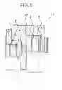
[FIG. 5]
FIG. 5 is a cross-sectional view of the cassette block shown in FIG. 4.
DESCRIPTION OF EMBODIMENTS
First Embodiment
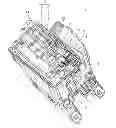
Referring now to FIGS. 1 to 3, an “electric junction box” according to a first embodiment of the invention is discussed. The electric junction box is designed to supply power and transmit signal to an electric component mounted onto an automobile.
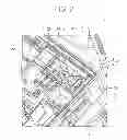
As shown in FIGS. 1 to 3, the electric junction box 1 is provided with a frame 4, a plurality of components to be attached to the frame 4, a side cover 5, and an upper cover and a lower cover (not shown). The frame 4 is composed of a cassette block 2, and a rack 3 having the cassette block 2 fitted thereinto. The side cover 5 is attached to the rack 3. Also, the cassette block 2, the rack 3, the side cover 5, the upper cover, and the lower cover are made of synthetic resin.
The forgoing cassette block 2 is provided with a bus bar groove to which a plurality of bus bar 6a, 6b, and 6c shown in FIG. 3 are attached, a component attachment part 22 to which the fuse 11, 12, and 13 and the relay 14 shown in FIG. 1 are attached, and a connector fitting part 21 into which a connector of an input power source line is fitted.
The plurality of bus bars 6a, 6b, and 6c is a wiring member that is made as by pressing metal plate, which branches via the fuses 11, 12, and 13 or the relay 14 electric power from a battery and an alternator. Also, the bus bar 6a is provided with a power source input portion 61 arranged within the component attachment part 22 and electrically connected to the forgoing connector of the input power source line. The power source input portion 61 is a portion in the bus bar 6a especially subjected to high temperature.
The foregoing rack 3 is provided with a rack-shaped outer wall 30 and a plurality of inner walls 31 arranged inside the outer wall 30.
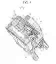
Also, as shown in FIG. 1, the electric junction box 1 is provided with a heart dissipation surrounding wall 7 just above the connector engagement part 21, i.e., just above the power source input portion 61. The heat dissipation surrounding wall 7 is composed of a part of the cassette block 2 and a part of the rack 3, inside which a heat dissipation space S is formed that any of the component avoids being attached to.
The heat dissipation surrounding wall 7 is, in detail, provided with three walls 23, 24, and 25 disposed in the cassette block 2, and an inner wall 31a disposed in the rack 3 as shown in FIG. 2. The three walls 23, 24, and 25 are continuous with each other in U-shape, and the wall 23 and the wall 25 are opposed to each other. By the cassette block 2 being fitted into the rack 3, the wall 24 and the inner wall 31a become opposed to each other.
In such the electric junction box 1, provision of the heat dissipation surrounding wall 7 just above the connector attachment part 21 makes the heat generated in the power source input portion 61 (“predetermined portion” in the claims) radiate upward where other components are not located without dissipating toward component attachment part 22 (a heat movement direction is shown by the arrow K in FIG. 2).
Second Embodiment
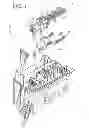
Referring now to FIGS. 4 and 5, an “electric junction box” related to a second embodiment is discussed. In the FIGS. 4 and 5 the same element as the aforementioned first embodiment is provided with the same reference sign and is not repeated here to discuss.
In this embodiment, the frame is composed of a cassette block 102, and a rack (not shown) into which the cassette block 102 is fitted. Also, in this embodiment, the heat dissipation surrounding wall 107 is formed integral with the cassette block 102 as shown in FIG. 4.
In such the electric junction box, as is the case with the electric junction box of the first embodiment, the heat dissipation surrounding wall 107 is disposed just above the connector attachment part 21, and thereby the heat generated in the power source input portion is made possible to radiate upward where other components are not located without dissipating toward component attachment part 22 (a heat movement direction is shown by the arrow K in FIG. 5).
Furthermore, while in the first embodiment and the second embodiment mentioned above, the frame is composed of separated cassette block and rack, the cassette block and the rack may, in the present invention, be formed integrally.
Furthermore, while in the first embodiment and the second embodiment mentioned above, the heat dissipation surrounding wall 7 or 107 is disposed just above the cassette attachment part 21, i.e., the power source input portion 61, the heat dissipation surrounding wall in the invention may be disposed just above any portion such as but not limited to the power source input portion 61, where heat dissipation of the bus bar is required.
Note that the aforementioned embodiments merely typically discloses the present invention, and are not intended to limit the invention. Namely, unless otherwise such changes and modifications depart from the scope of the present invention hereafter defined, they should be construed as being included therein.
REFERENCE SIGNS LIST
1 electric junction box
2, 102 cassette block
3 rack
4 frame
6a bus bar
7, 107 heat dissipation surrounding wall
61 poser source input part (predetermined portion)
Claims
1. An electric junction box, comprising:
a frame to which a plurality of components including a bus bar is attached; and
a heat dissipation surrounding wall disposed just above a predetermined portion of the bus bar in the frame,
wherein any of the components avoids being attached to an inside of the heat dissipation surrounding wall.
2. The electric junction box as claimed in claim 1, wherein the frame is provided with a cassette block, and a rack having the cassette block fitted thereinto, and wherein the heat dissipation surrounding wall is composed of a part of the cassette block and a part of the rack.
3. The electric junction box as claimed in claim 1, wherein the frame is provided with a cassette block, and a rack having the cassette block fitted thereinto, and wherein the heat dissipation surrounding wall is formed integral with the cassette block.
4. The electric junction box as claimed in claim 1, wherein the predetermined portion corresponds to a power source input portion of the bus bar.
5. The electric junction box as claimed in claim 2, wherein the predetermined portion corresponds to a power source input portion of the bus bar.
6. The electric junction box as claimed in claim 3, wherein the predetermined portion corresponds to a power source input portion of the bus bar.
Images & Drawings included:

Sources:
- United States Patent and Trademark Office - verify current appl. status at the USPTO↗
Similar patent applications:
- » 20210197742
Electrical junction box, manufacturing apparatus of electrical junction box, manufacturing method of electrical junction box, and wire harness - » 20160197462
Gasket for electrical junction box of railcar and electrical junction box of railcar - » 20180337522
Electrical junction box and waterproofing structure for electrical junction box - » 20200091666
Electrical junction box and method for manufacturing electrical junction box - » 11455775
Terminal connection structure, electrical junction box having the terminal connection structure, and method for assembling the electrical junction box - » 20140083733
Storing Box and Electrical Junction Box - » 20140020948
Storing box and electrical junction box - » 20150171608
Waterproof box and electric junction box equipped with same - » 20130032371
Waterproof box and electrical junction box having the same - » 20070167040
Electric junction box including electric unit in plural shield case members
Recent applications in this class:
- » 20250282312 2025-09-11
Vehicle Electronic Component Holder Set And Vehicle Electronic Component Holder - » 20250263032 2025-08-21
Catching Mechanism for Mounting Modules in an Agricultural Machine - » 20250229734 2025-07-17
CONTROL DEVICE FOR A VEHICLE AND METHOD OF MANUFACTURING A CONTROL DEVICE FOR A VEHICLE - » 20250162525 2025-05-22
VEHICULAR CIRCUIT BODY - » 20250115198 2025-04-10
HIGH VOLTAGE JUNCTION BOX - » 20250100481 2025-03-27
ELECTRICAL JUNCTION BOX - » 20240399985 2024-12-05
OUTLET BOX - » 20240391402 2024-11-28
VEHICLE CONTROL DEVICE AND VEHICLE EMPLOYING DEVCE - » 20240308450 2024-09-19
JUNCTION BOX ASSEMBLY HAVING A RIB FOR REINFORCING AN OUTER WALL - » 20240300427 2024-09-12
ELECTRONIC MODULE WITH SELF-RETAINING FEATURE AND METHOD OF USING SAME
Recent applications for this Assignee:
- » 20250293495 2025-09-18
WIRE HARNESS - » 20250292932 2025-09-18
WIRE HARNESS AND EXTERIOR MEMBER - » 20250289379 2025-09-18
WIRE HARNESS WIRING STRUCTURE AND WIRE HARNESS - » 20250287515 2025-09-11
ELECTRONIC CONTROL UNIT - » 20250286357 2025-09-11
ELECTRONIC CONTROL UNIT - » 20250286356 2025-09-11
WATERPROOF STRUCTURE AND WIRE HARNESS - » 20250279617 2025-09-04
CONNECTOR - » 20250279616 2025-09-04
CONNECTOR - » 20250273916 2025-08-28
CONNECTOR - » 20250273894 2025-08-28
CONNECTOR