Electronic component and printed circuit board with RFID tag
US20140183267A1
2014-07-03
13/974,165
2013-08-23
✅ Patent granted
US 8,905,319 B2
2014-12-09
-
-
Edwyn Labaze
Novak Druce Connolly Bove + Quigg LLP
2033-08-23
Abstract:
A printed circuit board (PCB) includes a base board, a number of electronic components and at least one radio frequency identification (RFID) tag. The electronic components are mounted on the base board. The at least one RFID tag is attached to one or more of the electronic components, and is programmed with identification information of the PCB.
Assignee:
- HON HAI PRECISION INDUSTRY CO., LTD. 10,014 🇹🇼 New Taipei, Taiwan
- HONG FU JIN PRECISION INDUSTRY (ShenZhen) CO., LTD. 2,585 🇨🇳 Shenzhen, China
Applicant:
Interested in similar patents?
Get notified when new applications in this technology area are published.
Classification:
G06K19/07758 » CPC main
Record carriers for use with machines and with at least a part designed to carry digital markings characterised by the kind of the digital marking, e.g. shape, nature, code; Record carriers with conductive marks, printed circuits or semiconductor circuit elements, e.g. credit or identity cards also with resonating or responding marks without active components with integrated circuit chips; Constructional details, e.g. mounting of circuits in the carrier the record carrier being capable of non-contact communication, e.g. constructional details of the antenna of a non-contact smart card arrangements for adhering the record carrier to further objects or living beings, functioning as an identification tag
G06K19/077 IPC
Record carriers for use with machines and with at least a part designed to carry digital markings characterised by the kind of the digital marking, e.g. shape, nature, code; Record carriers with conductive marks, printed circuits or semiconductor circuit elements, e.g. credit or identity cards also with resonating or responding marks without active components with integrated circuit chips Constructional details, e.g. mounting of circuits in the carrier
G05B19/4183 » CPC further
Programme-control systems electric; Total factory control, i.e. centrally controlling a plurality of machines, e.g. direct or distributed numerical control [DNC], flexible manufacturing systems [FMS], integrated manufacturing systems [IMS], computer integrated manufacturing [CIM] characterised by data acquisition, e.g. workpiece identification
H05K1/0266 » CPC further
Printed circuits; Details Marks, test patterns or identification means
H05K1/0266 » CPC further
Printed circuits; Details Marks, test patterns or identification means
H05K1/181 » CPC further
Printed circuits; Printed circuits structurally associated with non-printed electric components associated with surface mounted components
H05K1/181 » CPC further
Printed circuits; Printed circuits structurally associated with non-printed electric components associated with surface mounted components
H05K2201/10098 » CPC further
Indexing scheme relating to printed circuits covered by; Details of components or other objects attached to or integrated in a printed circuit board; Types of components Components for radio transmission, e.g. radio frequency identification [RFID] tag, printed or non-printed antennas
H05K2201/1053 » CPC further
Indexing scheme relating to printed circuits covered by; Details of components or other objects attached to or integrated in a printed circuit board; Details of mounted components; Involving several components Mounted components directly electrically connected to each other, i.e. not via the PCB
G06K19/06 IPC
Record carriers for use with machines and with at least a part designed to carry digital markings characterised by the kind of the digital marking, e.g. shape, nature, code
G05B19/418 IPC
Programme-control systems electric Total factory control, i.e. centrally controlling a plurality of machines, e.g. direct or distributed numerical control [DNC], flexible manufacturing systems [FMS], integrated manufacturing systems [IMS], computer integrated manufacturing [CIM]
H05K1/02 IPC
Printed circuits Details
H05K1/02 IPC
Printed circuits Details
H05K1/18 IPC
Printed circuits Printed circuits structurally associated with non-printed electric components
H05K1/18 IPC
Printed circuits Printed circuits structurally associated with non-printed electric components
Description
BACKGROUND
1. Technical Field
The disclosure generally relates to electronic components, and particularly relates to an electronic component and a printed circuit board with radio frequency identification (RFID) tags.
2. Description of the Related Art
To manage and track printed circuit boards (PCB), the PCBs are labeled with barcodes. However, such labeling requires a clear space on the PCB, making it difficult to further miniaturize the PCBs. Additionally, such labeling may be degraded by high temperatures or be worn away by handling.
Therefore, there is room for improvement within the art.
BRIEF DESCRIPTION OF THE DRAWINGS
Many aspects of the present disclosure can be better understood with reference to the following drawings. The components in the drawings are not necessarily drawn to scale, the emphasis instead being placed upon clearly illustrating the principles of the present embodiments.
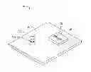
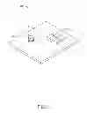
FIG. 1 is an assembled view of a printed circuit board (PCB) with RFID tags, according to an exemplary embodiment.
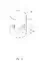
FIG. 2 is a schematic view of a capacitor mounted on the PCB in FIG.1.
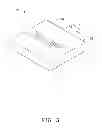
FIG. 3 is a schematic view of an inductor mounted on the PCB in FIG.1.
DETAILED DESCRIPTION
FIG. 1 is an assembled view of a printed circuit board (PCB) 100 with RFID tags, according to an exemplary embodiment. The PCB 100 includes a base board 10, a plurality of electronic components, and at least one RFID tag 70. In one exemplary embodiment, the plurality of electronic components includes a capacitor 30 and an inductor 50. Both of the capacitor 30 and the inductor 50 are mounted on a side of the base board 10, to receive alternating current (AC) or direct current (DC) from the base board 10.
In FIG. 2, the capacitor 30 includes a capsule 32 made of metal or plastic. In one exemplary embodiment, the capsule 32 is a cylinder, and includes a peripheral wall 34.
In FIG. 3, the inductor 50 includes a shell 52 made of metal or plastic. In one exemplary embodiment, the shell 52 is cube-shaped, and includes a top wall 54.
The RFID tag 70 is a passive electronic component, and works at frequencies of about 125 kHz, 133 kHz, 13.56 MHz, 27.12 MHz, 433 MHz, 902-928 MHz, 2.45 GHz, or 5.8 GHz, for example. The RFID tag 70 is attached to the plurality of electronic components. For example, the RFID tag 70 can be adhered to the peripheral wall 34 of the capacitor 30 via adhesive. For another example, the RFID tag 70 can be bonded on the top wall 54 of the inductor 50 using known processes. Because the RFID 70 is a passive component, it will not electronically interfere with the plurality of electronic components.
The RFID tag 70 includes a microchip 72 and an induction coil 74 electronically connected to the microchip 72. The induction coil 74 inducts a magnetic field generated by the alternating current of the PCB 100, and thus outputs a driving current to turn on the microchip 72. Thus, the microchip 72 does not need other power sources. The microchip 72 stores predetermined identification information of the PCB 100 such as name, production date, type, and other related information. The RFID tag 70 communicates with a RFID reader (not shown) via the induction coil 74, to send the predetermined identification information to the RFID reader. Thus, the PCB 100 can be managed and tracked.
Since the RFID tag 70 is mounted on the plurality of electronic components, a clear space on the base board 10 is not needed. Thus, design and manufacture of the PCB 100 is simplified and reduces costs.
In other exemplary embodiments, the RFID tag 70 can be mounted on other suitable locations of the capacitor 30 and the inductor 50 or other permanently mounted components with suitable surfaces.
In other exemplary embodiments, the plurality of electronic components can further include other elements, such as connectors, for example.
In summary, the RFID tag 70 is mounted on one or more of the plurality of electronic components which are permanently mounted on the base board 10. Thus, this is very convenient for users in managing and tracking the PCB 100.
It is to be understood, however, that even though numerous characteristics and advantages of the exemplary disclosure have been set forth in the foregoing description, together with details of the structure and function of the exemplary disclosure, the disclosure is illustrative only, and changes may be made in detail, especially in the matters of shape, size, and arrangement of parts within the principles of the exemplary disclosure to the full extent indicated by the broad general meaning of the terms in which the appended claims are expressed.
Claims
What is claimed is:1. A printed circuit board (PCB), comprising:
a base board;
a plurality of electronic components mounted on the base board; and
at least one radio frequency identification (RFID) tag mounted on the plurality of electronic components, and the at least one RFID tag storing predetermined identification information of the PCB.
2. The PCB as claimed in claim 1, wherein the plurality of electronic components comprises a capacitor, the at least one RFID tag is mounted on the capacitor.
3. The PCB as claimed in claim 2, wherein the capacitor has a peripheral wall, and the at least one RFID tag is adhered to the peripheral wall via adhesive.
4. The PCB as claimed in claim 1, wherein the plurality of electronic components comprises an inductor, the at least one RFID tag is attached to the inductor.
5. The PCB as claimed in claim 4, wherein the inductor comprises a shell having a top wall, and the at least one RFID tag is bonded on the top wall.
6. The PCB as claimed in claim 1, wherein the least one RFID tag is a passive electronic component.
7. The PCB as claimed in claim 6, wherein the least one RFID tag comprises a microchip and an induction coil electronically connected to the microchip, the induction coil inducts a magnetic field generated by the base board, and outputs a driving current to turn on the microchip.
8. The PCB as claimed in claim 7, wherein the predetermined identification information is stored in the microchip.
9. A printed circuit board (PCB), comprising:
a base board, the base board integrating a plurality of electronic components, and at least one of the plurality of electronic components provided with a radio frequency identification (RFID) tag;
wherein the RFID tag stores predetermined identification information of the PCB.
10. The PCB as claimed in claim 9, wherein the plurality of electronic components comprises a capacitor, the at least one RFID tag is attached to the capacitor.
11. The PCB as claimed in claim 9, wherein the plurality of electronic components comprises an inductor, the at least one RFID tag is mounted on the inductor.
12. An electronic component, comprising:
a radio frequency identification (RFID) tag comprising a microchip and an induction coil electronically connected to the microchip; the microchip and the induction coil both attached to an external wall of the electronic component.
13. The electronic component as claimed in claim 12, wherein the electronic component is a capacitor having a peripheral wall, and the RFID tag is adhered to the peripheral wall via adhesive.
14. The electronic component as claimed in claim 12, wherein the electronic component is an inductor having a top wall, and the RFID tag is bonded on the top wall.
Images & Drawings included:
Sources:
- United States Patent and Trademark Office - verify current appl. status at the USPTO↗
Recent applications in this class:
- » 20250245470 2025-07-31
PACKAGE EMBODIMENT COMPRISING A RFID/NFC LABEL - » 20250181880 2025-06-05
AN EMERGENCY MEDICAL INFORMATION DEVICE - » 20250181879 2025-06-05
WIRELESS TAG COMMUNICATION APPARATUS, WIRELESS TAG COMMUNICATION SYSTEM, AND COMMUNICATION METHOD FOR A WIRELESS TAG COMMUNICATION APPARATUS - » 20250139401 2025-05-01
WIRELESS IDENTIFICATION TAGS AND CORRESPONDING READERS - » 20250117622 2025-04-10
MOUNTS FOR TRACKING DEVICES - » 20250077827 2025-03-06
SYSTEMS AND METHODS FOR REMOTELY MONITORING DEVICE HEALTH - » 20250068880 2025-02-27
Systems and Methods for Improving Tag Locationing - » 20250036909 2025-01-30
ARTICLE WITH EMBEDDED RFID LABELS AND METHODS OF MANUFACTURE THEREOF - » 20250028927 2025-01-23
SYSTEMS, DEVICES AND METHODS OF TRACKING INVENTORY - » 20250021785 2025-01-16
RECESSABLE RFID FASTENER
Recent applications for this Assignee:
- » 20250218287 2025-07-03
METHOD OF GENERATING AND PROMPTING TRAFFIC INFORMATION, AND ROADSIDE DEVICE THEREOF - » 20250178535 2025-06-05
METHOD FOR CONSTRUCTING 3D PANORAMIC VIEW MODEL, VEHICLE-MOUNTED DEVICE, AND STORAGE MEDIUM - » 20250074444 2025-03-06
METHOD FOR EARLY WARNING A BLIND AREA, ELECTRONIC DEVICE AND STORAGE MEDIUM - » 20240416754 2024-12-19
DISPLAY CONTROL DEVICE, DISPLAY EQUIPMENT, AND VEHICLE EMPLOYING DEVICE - » 20240411051 2024-12-12
Light-emitting device array and optical transceiver system having the same - » 20240324114 2024-09-26
DISPLAY CONTROL DEVICE AND VEHICLE EMPLOYING DEVICE - » 20240295957 2024-09-05
METHOD FOR CONTROLLING ELECTRONIC DEVICE, ELECTRONIC DEVICE AND COMPUTER STROAGE MEDIUM EMPLOYING METHOD - » 20240257357 2024-08-01
METHOD FOR DETECTING OBSTACLES, ELECTRONIC DEVICE, AND STORAGE MEDIUM - » 20240203133 2024-06-20
LANE LINE RECOGNITION METHOD, ELECTRONIC DEVICE AND STORAGE MEDIUM - » 20240194999 2024-06-13
Robot using limiting device for locking battery